26
_ _ _-. ‘, : i - - - - XL-3 SECURITY SYSTEM OWNERS MANUAL FIRE BURGLARY INSTRUMENTS, INC. N9115 5/92 01992, FBX

_ _ _-.
‘, : i
- - - - XL-3
SECURITY SYSTEM
OWNERS MANUAL
FIRE BURGLARY INSTRUMENTS, INC. N9115 5/92 01992, FBX
INTRODUCTION
Congratulations on your decision to protect your home or business with the XL-3 series security system. You have chosen a reliable, state of the art securii system that is remarkably easy to operate. Your system has been professionally -
j installed by your local security company who can explain the specifics of your system within your location.
i The keypad is the arming station for your security system. These are available keypads for your system:
XL4612RM Metal plate keypad containing indicator lights for each of the 12 zones (areas of protection). This keypad can be flush mounted into your wall or surface mounted in a back box.
XL 461294 This is a surface mount keypad with 12 LEDs for monitorfng ZQ”‘\ status. ‘1 ,/
I 7015 Keypad with a plastic case and with indicator lights to show the status of I each of the zones. The zone indicator lights are located behind the plastic
sliding door of the keypad (left hand side). NOTE: This keypad displays zone status indication lights for 16 zones.
I 7005 Keypad with a plastic case and a two line LCD (liquid crystal display) with ’ I a two line readout.
Please identify the keypad(s) present on your system from the diagrams shown I in the sections that follow.
I The XL-3 is the Residential version of’ the which has been Listed by Underwriters Laboratories for household Fire and Burglary applications.
I The model XL-3B is the Commercial Burglary configuration of the control panel
I and has been Listed by Underwriters Laboratories for Commercial Burglary applications.
I ‘XL-3 USER’S MANUAL Page 1

1
TABLE OF CONTENTS
1. KEYPAD LAYOUT XL4612RM and XL4612SM 2. KEYPAD LAYOUT 7015 and 7005 3. KEYPAD CONVENTIONS 4. ARMING THE SYSTEM 5. DISARMING 6. STAY 7. INSTANT 8. INSTANT-STAY 9. BYPASS 10. UNBYPASS 11. USER DEFINITION
8
USER DELETION ’ KEYPAD AUXILIARV CONDITIONS DURESS
15: ARM-ONLY (MAID) CODE 16. DOOR STRIKE USER CODE 17. KEY PAD TAMPER 18. QUICK ARMING 19. QUICK FORCED ARMING 20. SET TIME OF DAY 21. ZONE DIRECTORY 22. SET AUTO-ARM TIME 23. CHIME MODE 24. READ CLOCK TIME 25. READ AUTO-SET TIME 26. DOOR STRIKE COMMAND 27. INSTALLATION LAYOUT 28. SYSTEM TESTING
3 4
z 7 8 8 9 9 10 10 11 11 11 11 12 12 12 12 12 12 13 13 13 13 13 14 15
FCC STATEMENT 16 LIMITATIONS STATEMENT 17 OWNERS INFORMATION 19 NOTES 20 SUMMARY 22 WARRANTY 23
XL-3 USER’S MANUAL Page 2
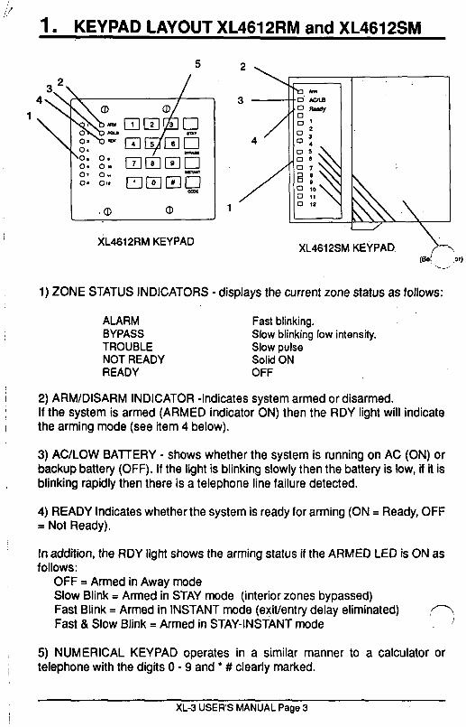
1. KEYPAD LAYOUT XL4612RM and XL4612SM
c I
XL4612RM KEYPAD XL461 2SM KEVPAD + W! ,Jr) L-1
1) ZONE STATUS INDICATORS - displays the current zone status as follows:
ALARM Fast blinking. BYPASS Slow blinking low intensity. TROUBLE Slow pulse NOT READY Solid ON READY OFF
2) ARM/DISARM INDICATOR -indicates system armed or disarmed. If the system is armed (ARMED indicator ON) then the RDY light will indicate the arming mode (see item 4 below).
3) AC/LOW BATTERY - shows whether the system is running on AC (ON) or backup battery (OFF). If the light is blinking slowly then the battery is low, if it is blinking rapidly then there is a telephone line failure detected.
4) READY Indicates whether the system is ready for arming (ON = Ready, OFF = Not Ready).
In addition, the RDY light shows the arming status if the ARMED LED is ON as follows:
OFF = Armed in Away mode Slow Blink = Armed in STAY mode (interior zones bypassed) Fast Blink = Armed in INSTANT mode (exit/entry delay eliminated) ,/7 Fast & Slow Blink = Armed in STAY-INSTANT mode !
5) NUMERICAL KEYPAD operates in a similar manner to a calculator or telephone with the digits 0 - 9 and l # clearly marked.
XL-3 USER’S MANUAL Page 3

2. KEYPAD LAYOUT 7015 and 7005
7 4 2
a- MODEL7OOS LCD KEYI’AD MODEL7015 LED KEYPAD
The 7015 contains indicator lights for the zone status, and the 7005 keypad contains a two line English language display. 1) ZONE STATUS INDICATORS - Your protected location has been divided into areas of protection known as zones. The zone indicators display the current status of each zone as follows:
ALARM Fast blinking. BYPASS Slow blinking low intensity. TROUBLE Slow pulse NOT READY Solid ON READY OFF
2) READY Indicates whether the system is ready for arming. 3) ARM/DISARM IND. Indicates system is armed (ON)/disarmed (OFF). 4) STAY- indicates system is armed with the interior zones bypassed. 5) INSTANT - Indicates system is ARMED with all delay zones instant. 6) AC - indicates system is running on AC,(ON) or backup battery (OFF). 7) BAT - Indicates low battery. Slow pulse = low battery, OFF = Normal 8) COM Indicates a communications failure with the Central station 9) NUMERICAL KEYPAD operates in a similar manner to a calculator or telephone with the digits 0 - 9 and l # clearly marked. 10) DISPLAY AREA - This section of the LCD keypad displays the current system status in this two line display. The second line of this display can be
* rogrammed by your installer to contain customized descriptors for the areas f protection within your location. The OFF-NORMAL installer programming
mode is identified by a flashing READY (on LED models) and by the display “PROGRAM MODE’ on LCD keypads.The panel is disabled in this mode. Call for service if this condition persists.
XL-3 USER’S MANUAL Page 4

ii /3. KEYPAD CONVENTIONS i
i Throughout this users manual the following conventions are used to display the keystrokes required to perform the functions.
BYPASS Key labeled BYPASS on keypad. INSTANT STAY
Key labeled INSTANT on keypad Key labeled STAY on keypad.
CODE Key labeled CODE on keypad l?JSJW Four digit user code.
4. ARMING THE SYSTEM ARMING the system will activate all portions of your Security System. Arming can only be performed if all zones are READY. For example, if a protected door is open the system cannot be armed.
SYSTEMREADY The system is ready to be armed if the READY indicator light ON (LED- basq? keypads). On LCD-based keypads the following display will appear: ._ /’
1 SYSTEM READY I
If the system is ready, ARMING can be performed as follows;
ARMING PROCEDURE: 1. Enter your four digit user code into the keypad: [USER]
The ARMED indicator light wili’now be lit and if you are leaving the home you may exit through a door designated by your installer as an exit/entry zone for a fixed time period known as the exit delay. The entry exit times for your system are as follows;
ENTRY: seconds- EXIT: seconds
LCD keypads will display the following message;
NOTE: For commercial systems (XLSB) installation, a 2 sec. Bell Test is provided. Following receipt of the off-premise transmission from the control at the central station, several beeps are heard from the keypad as confirmation. : If neither of these conditions occur, CALL FOR SERVICE. I p’
I NOTE: The system can be armed without the backup battery connected., ’
XL-3 USER’S MANUAL Page 5

SYSTEM NOT READY
If the system is not ready to be armed the READY indicator will be OFF. On LED based keypads the zone indicator lights will .display the zones which are currently not re,ady. The condition of each zone indicator reflects the status of each zone as follows;
ALARM Fast blinking TROUBLE Slow pulse NOT READY Solid ON BYPASS Slow blinking/low intensity
The LCD keypad a display indicates the system is not ready followed by displays showing the zone number and description of the faulted zone. For example:
SYSTEM NOT READY
In this example, the front door is not ready (Zone 1). In order to make the system ready determine which zones are not ready by observing the zone indicator lights, or the display section of the LCD keypad. From the zone number you can find out which area of protection is not ready, For example, assume the zone 1 is not ready. Typically, this might mean that a protected door or window is open.
l Once the problems with each zone have been resolved the READY light will appear and the system can be armed.
To ARM the system when the system is NOT READY one of the following actions are necessary:
l Make the zone(s) ready. Determine which zones are not ready and perform what is necessary to ready the zone(s) (example, close the door or window, etc.), or
. Bypass the zone(s) not ready. Bypassing should only be performed if the zone cannot be made ready or intentionally will remain not ready. Zones that are bypassed are not protected when the system is armed.
XL-3 USER’S MANUAL Page 6’

’
/” /~ DISARMING
f
Disarming the security system will deactivate the system’s burglary function. This procedure can also be used to reset your system if you accidentally set off the system (example, o#ened a window while the system was armed, or excessive amount of smoke activated fire protection system).
DISARM PROCEDURE: [US.ER] ’ Enter your user code.
IF NO ALARMS HAVE TAKEN PLACE Upon disarming the ARMING indicator will go off. The system display will reflect the current status. LCD keypads should display the SYSTEM READY display.
IF ALARMS HAVE TAKEN PLACE If alarms or other conditions such as system troubles have taken place sincr? the initial system arming, they will appear on the display. The conditions thh. 1 have occurred appear in the zone display section of the keypad. LED based keypads will reflect the current system status through the indicator lights as follows;
ALARM Fast blinking. BYPASS Slow blinking low intensity. TROUBLE Slow pulse NOT READY Solid ON
Burglary alarms will be indicated with a STEADY sound through the keypad while FIRE alarms will generate a pulsing sound. LCD keypads will show the alarm conditions with a display as follows:
This display shows the zones in alarm. After entry of your four digit user code the following display will appear:
If an intrusion has taken place while you were away, do not enter until the location has been securedl!!. Call for help from a neighbor’s phone.
. To clear the display of the alarm or trouble conditions and silence the audible signal enter [USER] again. /-
. . .
XL~USER’SWU~LPage7
6. STAY The STAY mode deactivates any interior protection zones and you will be free to walk throughout your location without activating the alarm system. To enter the STAY mode, the system must be READY. (see previous descrtptlon).
STAY PROCEDURE: STAY [USER]
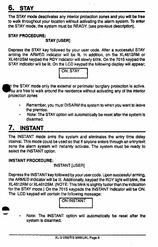
Depress the STAY key followed by your user code. After a successful STAY arming the ARMED indicator will be lit. In addition, on the XL4612RM or XL461 2SM keypad the RDY indicator will slowly blink. On the 7015 keypad the STAY indicator will be lit. On the LCD keypad the following display will appear;
a the STAY mode only the external or perimeter burglary protection is active. ou are free to walk around the residence without activating any of the interior
protection zones
. Remember, you must DISARM the system to when you want to leave the premise.
. Note: The STAY option will automatically be reset after the system is disarmed.
7. INSTANT The INSTANT mode arms the system and eliminates the entry time delay interval. This mode could be used so that if anyone enters through an entry/exit zone the alarm system will instantly activate. The system must be ready to select the INSTANT option,
INSTANT PROCEDURE: INSTANT [USER]
Depress the INSTANT key followed by your user code. Upon successful arming, the ARMED indicator will be lit. Additionally, keypad the RDY light will blink, the XL461 2RM or XL461 2SM. (NOTE: This blink is slightly faster than the indication for the STAY mode.) On the 7015 keypads the INSTANT indicator will be ON. The LCD keypad will contain the following message:
m loN:INSTANT - . Note: The INSTANT option will automatically be reset after the
system is disarmed.
XL-3 USER’S MANUAL Page 8

-8. INSTANT - STAY _* ‘( .- x’ . . The INSTANT STAY ‘mode arms the system with the characteristics of both the
- INSTANT and STAY .modes with the interior portions bypassed and the entry delay suspended. The system must be READY to enter this mode.
PROCEDURE: INSTANT STAY [USER]
STAY LTANT [USER]
Depress the INSTANT and STAY keys in any order followed by your user code. After a successful INSTANT STAY arming the ARMED indicator will be lit. Additionally, the ROY light on XL461 2RM and 4612SM keypads will blink slowly then rapidly. On the 7015 keypads both the INSTANT and STAY lights will be ON-The 7005 keypad will contain the following message;
yF5Fmiq r \
,/ “. . You cannot exit the premises through an exit/entry zone while the
system is armed in this mode.
9. BYPASS Bypasses are performed to eliminate burglary zones that are not ready or faulty from activating the security system.
BYPASS PROCEDURE: BYPASS [USER] ZN
Depress the BYPASS key followed by your user code and two digit zone number (01-12) to be bypassed. Example: BYPASS [USER] 02 bypasses zone 2. If the zone has been bypassed already, the sequence will unbypass the zone (except if the system is armed and the unbypassed zone is still not ready). Unbypass returns the zone to protected status.
After the bypass (or unbypass) command has been accepted the unit will emit a continuous beep and bypassed zones appear in a slow blinking mode in the zone status area on the XL4612RM, XL4612SM or 7015 keypads. The 7005 LCD keypad displays the zone bypasses as a secondary display after the SYSTEM READY or SYSTEM NOT READY as shown below:
-1 If multiple zones are bypassed then more than one display will appears , Remember: Zones which are bypassed are not protected when the system is armed. Temporary users (i.e. babysitters) shall be shown the bypass procedure.
XL-3 USER’S MANUAL Page Q

10. UNBYPASS The UNBYPASS function removes an existing bypass from a currently bypassed zone. After UNBYPASSING a zone, the bypass removed for that zone on either the LCD or LED keypad. The procedure is similar to a bypass.
UNBYPASS PROCEDURE: BY PASS [USER] ZN See bypass description.
11. USER DEFINITION Users can be entered or modified directly through the keypad. The secur’ky system can have up to thirty different users. Users number 1 & number 2 are known as the master users and are the only users allowed to modify other user operating parameters.
USER DEFINITION PROCEDURE: CODE [USER] [US number ] [USERID]
ere; CODE is the CODE key on the keypad [USER] master user code [User number 1 or User number 2, four digits). [US number ] User number (01-30)+ [USID] New user ID (0000 - 9999).
Note: (+)lf ambush code capability has been enabled by your installing company then user number 30 will be used as the system ambush code. If an arming only code (maid code) has been defined by your installer then user number 29 can only arm the system. If a single user door strike code has been created by your installer then user number 28 is dedicated to that function.
Please check with your installer to determine whether any of these special purpose users codes exist.
Example: To create user number 13, with a user access code of 4667, (assume a’master user code of 1492), enter; CODE 1492 13 4567
. Any error detected during the USER definition process will cause the keypad to beep rapidly four times. If an error is detected retry the entire command.
Obvious codes like 1111 or 1234 should be avoided.
XL-3 USER’S MANUAL Page 10

12. USER DELETION Removal of users from the panel can be performed as follows;
USER DELETION PROCEDURE:
Where: CODE [USER] [User number ] #
CODE is the depression of the CODE key. [USER] Master user code [User number ] Represents the user number being deleted (03-30). Note: Master users (User number 1 or number 2) cannot be deleted. # is the # key from the keypad.
Example: Delete user number 26 (assume a master user code of 6789): CODE 6789 26 #
13. KEYPAD AUXILIARY CONDITIONS ,- The system can also initiate three separate AUXILIARY conditions dire&. j through the keypad. These conditions must be activated by your installer and can be initiated through simultaneous depression of two keys as follows:
KFYS- Panic l #
Fire 7 9 Aux. 1 3
For example, to initiate a keypad panic signal press the l and #keys at the same time. Consult with your alarm installer to determine the operation of these conditions within your system. In UL installations, the AUX alarm is silent. The 4612SM keypad has keys for specially defined auxiliary functions. Their functions are activated by simultaneously depressing two keys. NOTE: Consult your installer to determine the auxiliary functions of your system.
14. DURESS Ambush can be programmed by your installer to send an emergency signal to the Central Station if you are forced to enter the premises. If active, code number 30 is ambush code.
15. ARM-ONLY (MAID) CODE If selected by your installer, the user code number 29 can only arm the system. This allows a temporary worker to only arm the security system as they
XL-3 USER’S MANUAL Page 11

10. UNBYPASS The UNBYPASS function removes an existing bypass from a currently bypassed zone. After UNBYPASSING a zone, the bypass removed for that zone on either the LCD or LED keypad. The procedure is similar to a bypass.
UNBYPASS PROCEDURE: BYPASS [USER] ZN See bypass description.
11. USER DEFINITION Users can be entered or modified directly through the keypad. The security system can have up to thirty different users. Users number 1 & number 2 are known as the master users and are the only users allowed to modify otheruser operating parameters.
USER DEFINITION PROCEDURE: CODE [USER] [US number ] [USERID]
CODE is the CODE key on the keypad .’ ” [USER] master user code [User number 1 or User number 2, four digits). [US number ] User number (Ol-30)+ [USID] New user ID (0000 - 9999).
Note: (*)lf ambush code capability has been enabled by your installing company then user number 30 will be used as the system ambush code. If an arming only code (maid code) has been defined by your installer then user number 29 can only arm the system. If a single user door strike code has been created by your. installer then user number 28 is dedicated to, that function.
Please check with your installer to determine whether any of these special purpose users codes exist.
Example: To create user number 13, with a user access code of 4567, (assume a master user code of 1492), enter; CODE 1492 13 4567
. Any error detected during the USER definition process will cause the keypad to beep rapidly four times. If an error is detected retry the entire command.
Obvious codes like 1111 or 1234 should be avoided.
0
XL-3 USER’S MANUAL Page 10
12. USER DELETION Removal of users from the panel can be performed as follows;
USER DELETION PROCEDURE:
Where: CODE [USER] [User number ] #
CODE is the depression of the CODE key. [USER] Master user code [User number ] Represents the user number being deleted (03-30). Note: Master users (User number 1 or number 2) cannot be deleted. # is the # key from the keypad.
Example: Delete user number 26 (assume a master user code of 6789): CODE 6789 26 #
13. KEYPAD AUXILIARY’CONDITIONS The system can also initiate three separate AUXILIARY conditions direct,, through the keypad. These conditions must be activated by your installer and can be initiated through simultaneous depression of two keys as follows:
ON KEYSTROKES Panic ’ # Fire 7 9 Aux. 1 3
For example, to initiate a keypad panic signal press the l and #keys at the same time. Consult with your alarm installer to determine the operation of these conditions within your system. In UL installations, the AUX alarm is silent. The 4612SM keypad has keys for specially defined auxiliary functions. Their functions are activated by simultaneously depressing two keys. NOTE: Consult your installer to determine the auxiliary functions of your system.
14. DURESS Ambush can be programmed by your installer to send an emergency signal to the Central Station if you are forced to enter the premises. If active, code number 30 is ambush code.
. 15. ARM-ONLY (MAID) CODE i
If selected by your installer, the user code number 29 can only arm the system. This allows a temporary worker to only arm the security system as they leave.
,? ’ >.. /
XL3 USER’S MANUAL Page 11

16. DOOR STRIKE USER CODE * In certain installations there may be a door (or other device) which is programmed to activate by entering a user code. If configured by your installer, number 28 can be dedicated for this purpose. If programmed, then entering user number 28 will not arm or disarm the system but will activate an external device such as a door strike. This feature has not been investigated by UL. The system is not Listed for Access Control applications.
17. KEYPAD TAMPER If 21 characters have been entered without a valid user code or command, the keypad will beep continuously. Silence by entering a valid user code.
18. QUICK ARMING (# 1) When selected by the installer, this command will arm the system without entry
a user code. NOTE: System disarming will require a user code. To quick arm ter: # 1
19. QUICK FORCED ARM (# 2) When selected by the installer, this command (# 2) arms the system wtthout entering a user code and bypasses any unready burglary zones. Quick forced arm:# 2
20. SET TIME OF DAY ( # 3 ) The system contains a real-time clock for the auto-arming and system test capability. The time of day can be set through any keypad using the following’ command: # 3 [USER] HR MN
Time entry is performed in 24 hour time (military time). For exampleto set the clock for 10:25PM (assume a user code of 4567) enter: # 3 4567 20 25
l .NOTE: .lf the..system clock needs to be reset, the XL4612RM, XL461 2SM or 7015 keypads will blink rapidly,,in succession every 30 seconds. The 7005 keypad will display a message. This could occur if the time has never been set or if total system power (AC and battery) was removed for a prolonged period of time.
l Consult your installer to determine whether your user code is necessary for setting the time. This feature is disabled in UL installations.
@I. ZONE DIRECTORY (# 4 ) To view a list of the zone descriptors from the 7005 keypad, enter: # 4
XL-3 USER’S MANUAL Page 12

22. SET AUTO-ARM TIME (#5) Another option selectable by your installer is auto arming. This feature means that the system can be programmed to arm at a preprogrammed time every day. This will occur at the selected time if the system is not already armed. For example, if you have an 11:30 PM auto-arming time programmed and fall asleep without arming the system, the panel will automatically arm at 11:30.
WARNING INDICATOR Awarning signal can be selected by your installer to provide an audible warning two minutes prior to the auto- arming time. This warning will repeat every 30 seconds until the auto arming time. To disable, simply enter your four digit user code. The keypad will emit a beep and the indicator lights on LED based keypads will blink rapidly to acknowledge that you have removed the auto-arming time for the day.
HOW TO CHANGE THE AUTO-ARMING TIME To modify the auto-arming time enter: #5 [USER] HR MN. For example: than f-3 the auto-arming time to 11:45 PM (user code of 5678) enter: # 5 5878 23 45’< ’
. NOTE: All times are entered in 24 hour (military) time.
. This feature is disabled in UL installations.
23:CHIME MODE (#6) The optional chime mode causes the keypad to beep for one second every time selected zones such as the entrance door are opened while the system is disarmed. For example, this could inform you each time the front door was opened while you.were at home. To activate, press # 6 from the keypad. If the chime feature has already been turned on, another #6 will turn the feature off.
24. READ CLOCK TIME (#7) LCD Only Upon entering #7, the LCD display shows the current time.
25. READ AUTO SET TIME (#8) LCD O.nly Upon entering #8, LCD display shows the time that system will auto-arm.
26. DOdR STRIKE COMMAND (# 9 )’ if enabled by your installer a valid user can activate any of the system door strikes through the following command: # 9 [USER] [door strike number] For example: activate door strike 3 (with user code of 2468) enter: # 9 2468 3
XL-3 USER’S MANUAL Page 13
16. DOOR STRIKE USER CODE In certain installations there may be a door (or other device) which is programmed to activate by entering a user code. If configured by your installer, number 28 can be dedicated for this purpose. If programmed, then entering user number 28 will not arm or disarm the system but will activate an external device such as a door strike. This feature hasnot been investigated by UL. The system is not Listed for Access Control applications.
17. KEYPAD TAMPER If 21 characters have been entered without a valid user code or command, the keypad will beep continuously. Silence by entering a valid user code.
18. QUICK ARMING (# 1) When selected by the installer, this command will arm the system without entry
user code. NOTE: System disarming will require a user code. To quick arm
19. QUICK FORCED ARM (# 2) When selected by the installer, this command (# 2) arms the system without entering a user code and bypasses any unready burglary zones. Quick forced arm:# 2
20. SET TIME OF DAY ( # 3 ) The system contains a real-time clock for the auto-arming and system test capability. The time of day can be set through any keypad using the following command: # 3 [USER] HR MN
Time entry is performed in 24 hour time (military time). For example to set the clock for 10:25PM (assume a user code of 4567) enter: # 3 4567 20 25
. NOTE: if the system clock needs to be reset, the XL4612RM, XL481 2SM or 7015 keypads will blink rapidly in succession every 30 seconds. The 7005 keypad will display a message. This could occur if the time has never been set or if total system power (AC and battery) was removed for a prolonged period of time.
l Consult your installer to determine whether your user code is necessary for setting the time. This feature is disabled in UL installations.
@!I. ZONE DIRECTORY (# 4 ) To view a list of the zone descriptors from the 7005 keypad, enter: # 4
XL-3 USER’S MANUAL Page 12
22. SET AUTO-ARM TIME (#5) Another option selectable by your installer is auto arming. This feature means that the system can be programmed to arm at a preprogrammed time every day. This will occur at the selected time if the system is not already armed. For example, if you have an II:30 PM auto-arming time programmed and fall asleep without arming the system, the panel will automatically arm at 11:30.
WARNING INDICATOR Awarning signal can be selected by your installer to provide an audible warning two minutes prior to the auto- arming time. This warning will repeat every 30 seconds until the auto arming time. To disable, simply enter your four digit user code. The keypad will emit a beep and the indicator lights on LED based keypads will blink rapidly to acknowledge that you have removed the auto-arming time for the day.
HOW TO CHANGE THE AUTO-ARMING TIME To modify the auto-arming time enter: #5 [USER] HR MN. For example: chanrj the auto-arming time to 11:45 PM (user code of 5678) enter: # 5 5678 23 45
. NOTE: All times are entered in 24 hour (military) time. l This feature is disabled in UL installations.
23. CHIME MODE (#6) The optional chime mode causes the keypad to beep for one second every time selected zones such as the entrance door are opened while the system is disarmed. For example, this could inform you each time the front door was opened while you were at home. To activate, press # 6 from the keypad. If the chime feature has already been turned on, another #6 will turn the feature off.
24. READ CLOCK TIME (#7) LCD Only Upon entering #7, the LCD display shows the current time.
25. READ AUTO SET TIME (#8) LCD Only Upon entering #8, LCD display shows the time that system will auto-arm.
26. DOOR STRIKE COMMAND (# 9 ) If enabled by your installer a valid user can activate any. of the system door strikes through the following command: # 9 [USER] [door strike number] For example: activate door strike 3 (with user code of 2468) enter: # 9 2468 3
0 \ 1
XL-3 USER’S MANUAL Page 13

27. INSTALLATION LAYOUT. .:P ; i (., ,: 1,“ + .’ ‘,.
Early warning fire detection is best achieved by the installation of fire detection equipment the location as follows;
Typical Smoke Detector Layout
Preparation of an evacuation plan is of prime importance in fire prevention. Establish a household emergency evacuation plan in the event of fire. Refer to the Smoke Detector instructions for exact mounting, layout and spacing. 1. Evaluate possible escape routes from your home. 2- Select 2 escape routes from each room. 3. Rooms on the second floor should have a rope ladder. Be sure it will reach the ground. 4. Draw a sketch of your escape plan so everyone is familiar with it. 5. Practice your escape plan to assure that everyone knows what to do. 6. Establish a meeting place outside where your family is to report. Once you have evacuated the house do not return to a burning house. 7. Advise the local fire authority that you have installed a fire alarm system. 8. When the fire alarm signals, LEAVE IMMEDIATELY. Do not stop for belongings. 9. If a fire occurs Jest the door. If hot, use your alternate route. If the door is cool, brace your shoulder against it and open it cautiously. Shut the door to help prevent the fire and smoke from spreading. Crawl through smoke, holding your breath.
0. Contact the Fire Department from a neighbor’s telephone. a. Everyone including neighbors should be familiar with the Fire and Burglary
signals. In this installation the Fire Alarm signal is The Burglary Alarm signal is The fire alarm signal takes precedence over the burglar alarm signal.
XL-3 USER’S MANUAL Page 14

28. SYSTEM TESTING This Wfltml Unit was manufactured under rigid qualiiy standards. Maintenance IS best performed by your installing company with trained service personnel.
Installing Company: Telephone Number:
It is recommended that you test your system once a week using the following procedure:
. Note: If your system is monitored by a Central Station then contact them prior to performing this test.
I- Arm your security system. 2- Activate the system by opening a protected zone (example, window, or door). 3- Confirm that the alarm sounding device (bell or siren) activates. If your System is connected to a Central Station then the keypad will emit a ringb~-) sound to confirm that the signal was received. \\ / 4- Disarm the system to silence the system and return to normal status.
BATTERY TEST
In order to test the backup battery the following procedure should be performed;
l- Remove the AC transformer from the AC outlet by removing the restraining screw which secures the transformer to the wall. (Note: the screw is not present in models sold in Canada). 2- Observe that the AC light goes off on the keypad. 3- Activate your alarm system using steps l-4 listed above. 4- Replace the AC transformer to the AC outlet and secure using the retaining screw (Note: The retaining screw is not present in models sold in Canada).
The National Fire Protection Association publishes a standard for household fire warning equipment. N.F.P.A. #74. Further information can be obtained by contacting; NFPA Public Affairs Dept., Batterymarch Park, Quincy,MA 02269.
If you have any further questions about the operation of your system, call your installer.
XL-3 USER’S MANUAL Page 15
,
FEDERAL COMMUNICATIONS COMMISSION (FCC) STATEMENT
This equipment has been tested to FCC requirements and has been found acceptable for use. The FCC requires the following statement for your information.
This equipment generates and uses radio frequency energy and if not installed and used properly, that is in strict accordance with the manufacturer’s instructions may cause interference to radio and television reception. lt has been tested and found to comply with the limits of Part 15 of FCC Rules, which are designed to provide reasonable protection against such interference In a residential installation. However, there is no guarantee that interference will not occur in a particular installation. If this equipment does not cause interference to radio or television reception, which can be . determined by turning the equipment off and on, the user is encouraged to try to correct the interference by one or more of the following measures:lf using an indoor antenna, have a quality outdoor antenna installed.
. Reorient the receiving antenna until interference is reduced or eliminated.
. Move the radio or television receiver away from the control/ communicator.
. Move. the antenna leads away from any wire runs to the control/communicator.
. Plug the control/communicator into a different outlet so that it and the radio or television receiver are on different branch circuits.
ff necessary, the user should consult the dealer or an experienced radio/television technician for additional suggestions.
The user may find the following booklet prepared by the Federal Communications Commission helpful: “interference Handbook”. This booklet is available from ‘the U.S. Government Printing Office, Washington, DC 20402. Stock No. 004-000-00450-7.
The user shall not make any changes or modifications to the equipment unless authorized by the installation Instructions or User’s Manual. Unauthorized changes or modifications could void the user’s authority to operate the equipment.
IN THE EVENT OF TELEPHONE OPERAllONAL PROBLEMS In the event of telephone operational problems, disconnect the communicator by removing the plug from the RJ31 X jack. Do not disconnect the phone connection inside the communicator. Doing so will result in the loss of the phone works correctly after the communicator has been disconnected from the phone lines, the communicator has a problem and should be returned for repair.
port disconnecting the communicator, there is still a problem on your line, notify the a phone company that they have a problem and request prompt repair service. The <ser may not under any circumstances (in or out of warranty) attempt any service or
repairs on the system. lt must be returned to the factory or an authorized service agency for all repairs.
XL-3 USER’S MANUAL P-e 16
WARNING LIMITATIONS OF THIS ALARM SYSTEM
While this system is an advanced design security system, it does not offer guaranteed protection against burglary, fire or other emergency. ‘Any alarm system, whether commercial or residential, is subject to compromise or failure to warn for a variety of reasons. For example:
. Intruders may gain access through unprotected openings or have the technical sophistication to bypass an alarm sensor or disconnect an alarm warning device.
. Intrusion detectors (e.g., passive infrared detectors), smoke detectors, and many other sensing devices will not work without power. Battery operated devices will not work without batteries, with dead batteries or if the batteries are not put in properly. Devices powered solely by AC will not work if their AC power supply is cut off for any reason, however briefly.
l Signals sent by wireless transmitters may be blocked or reflected by ’ metal before they reach the alarm receiver. Even if the signal path has been recently checked during a weekly test, blockage can occur if a metal object is moved into the path.
. A user may not be able to reach a panic or emergency button quickly enough.
. While smoke detectors have played a key role in reducing residential fire deaths in the United States, they may not activate or provide early warning for a variety of reasons in as many as 35% of all fires, according to data published by the Federal Emergency Management Agency. Some of the reasons smoke detectors used in conjunction I with this System may not work are as follows: Smoke detectors may have been improperly installed and positioned. Smoke detectors may not sense fires that start where smoke cannot reach the detectors, such as in chimneys, in walls, or roofs, or on the other side of closed doors. Smoke detectors may not sense a fire on another level of a residence or building. A second floor detector, for example, may not sense a first floor or basement fire. Moreover, smoke detectors have sensing limitations. No smoke detector can sense every kind of fire every time. In general, detectors may not always warn about fires caused by carelessness and safety hazards like smoking in bed, violent explosions, escaping gas, improper storage of flammable materials, overloaded electrical circuits, children playing with matches, or arson. Depending on the nature of the fire and/or the location of the smoke detectors, the detector, even if it operates ?“, anticipated, may not provide sufficient warning to allow all occupant-,. to escape in time to prevent injury or death.
. Passive Infrared Motion Detectors can only detect intrusion within the designed ranges as diagramed in their installation manual. Passive
XL-3 USER’S MANUAL Page 17
Infrared Detectors do not provide volumetric area protection. They do create multiple beams of protection, and intrusion can only be detected in unobstructed areas covered by the beams. They cannot detect motion or intrusion that takes place behind walls, ceilings, floors, closed doors, glass partitions, glass doors, or window. Mechanical tampering, masking, painting, or spraying of any material on the mirrors, windows or any part of the optical system can reduce their detection ability. Passive Infrared Detectors sense changes in temperature; however, as the ambient temperature of the protected area approaches the temperature range of 90 to 15OF, the detection performance can decrease.
. Alarm warning devices such as sirens, bells or horns may not alert people or wake up sleepers who are located on the other side of closed or partly open doors. If warning devices sound on a different level of the residence from the bedrooms, then they are less likely to waken or alert people inside the bedrooms. Even persons who are awake may not hear the warning if the alarm is muff led by noise from a stereo, radio, air conditioner or other appliances, or by passing traffic. Finally, alarm warning devices, however loud, may not warn hearing-impaired people or waken deep sleepers.
l Telephone lines needed to transmit alarm signals from a premises to a central monitoring station may be out of service or temporarily out of setvice. Telephone lines are also subject to compromise by sophisticated intruders.
. Even if the system responds to the emergency,as intended, however, occupants may have insufficient time to protect themselves from the emergency situation. In the case of a monitored alarm system, authorities may not respond appropriately.
l This equipment, like other electrical devices, is subject to component failure. Even though this equipment is designed to last as long as 10 years, the electronic components could fail at any time.
The most common cause of an alarm system not functioning when an intrusion or fire occurs is inadequate maintenance. This alarm system should be tested weekly to make sure all sensors are working properly.
Installing an alarm system may make one eligible for lower insurance rates, but an alarm system is not a substitute for insurance. Homeowners, property owners and renters should continue to act prudently in protecting themselves and continue to insure their lives and property.
a continue to develop new and improved protection devices. Users of alarm >ystems owe it to themselves and their loved ones to learn about these developments.
XL-3 USER’S MANUAL Page 18
i
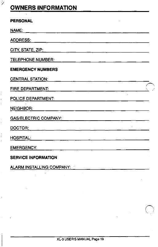
’ OWNERS INFORMATION
PERSONAL
ADDRESS:
CITY, STATE, ZIP:
TELEPHONE NUMBER:
EMERGENCY NUMBERS
CENTRAL STATION:
FIRE DEPARTMENT: \ /’
POLICE DEPARTMENT:
NEIGHBOR:
GAS/ELECTRIC COMPANY:
DOCTOR:
HOSPITAL:
EMERGENCY:
SERVICE INFORMATION
ALARM INSTALLING COMPANY:
c /
XL-3 USER’S MANUAL Page 19
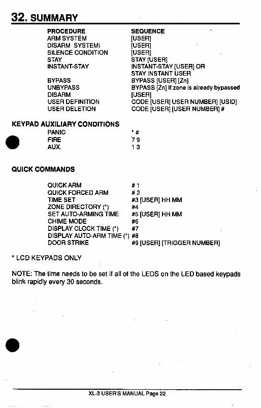
32. SUMMARY PROCEDURE ARM SYSTEM DISARM SYSTEMI SILENCE CONDITION STAY INSTANT-STAY
BYPASS UNBYPASS DISARM USER DEFINITION USER DELETION
KEYPAD AUXILIARY CONDITIONS PANIC FIRE AUX.
QUICK COMMANDS
QUICK ARM QUICK FORCED ARM TIME SET ZONE DIRECTORY (‘) SET AUTO-ARMING TIME CHIME MODE DISPLAY CLOCK TIME (‘)
SEQUENCE [USER1 [USER] [USER] STAY [USER] INSTANT-STAY [USER] OR STAY INSTANT USER BYPASS [USER] [Zn] BYPASS [Zn] If zone is already bypassed [USER] CODE [USER] USER NUMBER] [USID] CODE [USER] [USER NUMBER] #
l # 79 13
#1 #2 #3 [USER] HH MM #4 #5 [USER] HH MM #6 #7
DISPLAY AUTO-ARM TIME (‘) #8 DOOR STRIKE #9 [USER] [TRIGGER NUMBER]
l LCD KEYPADS ONLY
NOTE: The time needs to be set if all of the LEDS on the LED based keypads blink rapidly every 30 seconds.
XL-3 USER’S MANUAL Page 22

FIRE BURGLARY INSTRUMENTS, INC. ONE YEAR UMlTED WARRANTY Fire Burglary Instruments, Inc., a subsidiary of Pittway Corporation, its divisions, subsidiaries and affiliates (“Seller”), warrants its security equipment (“the product”) to be free from defects in materials and workmanship one year from the date of original purchase, under normal use and service. Seller’s obligation is limited to repairing or replacing, at its option, free of charge for parts, labor, or transportation, any product proven to be defective in materials or workmanship under normal use and service. Seller shall have no obligation under this warranty or otherwise if the product is altered or improperly repaired or serviced by anyone other than Seller. In case of defect, contact the securii professional who installed and maintains your security equipment or the Seller for product repair. This one year Limited Warranty is in lieu of all other express warranties, obligations or liabilitiesTHERE ARE NO EXPRESS WARRANTIES WHICH EXTEND BEYOND THE FACE HEREOF.ANY IMPLIED WARRANTIES, OBLIGATIONS OR LIABILITIES MADE BY SELLER IN CONNECTION WITH THIS PRODUCT, INCLUDING ANY IMPLIF WARRANTY OF MERCHANTA.BILITY, OR FITNESS FOR A PARTICULAR PURPG. ’
-?
OR OTHERWISE, ARE LIMITED IN DURATION TO A PERIOD OF ONE YEAR FROM THE DATE OF ORIGINAL PURCHASE. ANY ACTION OR BREACH OF ANY WARRANTY, INCLUDING BUT NOT LIMITED TO ANY IMPLIED WARRANTY OF MERCHANTABILITY, MUST BE BROUGHT WITHIN 18 MONTHS FROM DATE OF ORIGINAL PURCHASE. IN NO CASE SHALL SELLER BE LIABLE TO ANYONE FOR ANY CONSEQUENTIAL OR INCIDENTAL DAMAGES FOR BREACH OF THIS OR ANY OTHER WARRANTY, EXPRESS OR IMPLIED, OR UPON ANY OTHER BASIS OF LIABILITY WHATSOEVER, EVEN THE LOSS OR DAMAGE IS CAUSED BY ITS OWN NEGLIGENCE OR FAULT. Some states do not allow limitation on how long an implied warranty lasts or the exclusion or limitation on how long an implied warranty lasts or the exclusion or limitation of incidental or consequential damages, so the above limitation or exclusion may not apply to you. Seller does not represent that the products it sells may not be compromised or circumvented; that the product will prevent any personal injury or property loss by burglary, robbery, fire or otherwise; or that the product will in all cases provide adequate warning or protection. Buyer understands that a properly installed and maintained alarm may only reduce the risk of a buiglary, robbery, or fire or other events occurring without providing an alarm, but it is not insurance or a guarantee that such will not occur or that there will be no personal injury or property loss as a result. CONSEQUENTLYSELLER SHALL HAVE NO LlA,BlLlTY FOR ANY PERSONAL INJURY, PROPERTY DAMAGE OR OTHER LOSS BASED ON A CLAIM THE PRODUCT FAILED TO GIVE WARNING. HOWEVER, IF SELLER IS HELD LIABLE, WHETHER DIRECTLY OR INDIRECTLY, FOR ANY LOSS OR DAMAGE ARISING UNDER THIS LIMITED WARRANTY OR OTHERWISE, REGARDLESS OF CAUSF OR ORIGINSELLERS MAXIMUM LIABILITY SHALL NOT IN ANY CASE EXCE\, (7
THE PURCHASE PRICE OF’THE PRODUCT, WHICH SHALL BE THE COMPLEIt ’ AND EXCLUSIVE REMEDY AGAINST SELLER. This warranty gives you specific legal rights, and you may also have other rights which vary from state to state. No increase or alteration, written or verbal, of the obligations of this Limited Warranty is authorized.


