Page 1
1
ModelicaML: Getting Started Issue 1.8.1
November 20, 2013
Wladimir Schamai
EADS Innovation Works (Hamburg, Germany)
Linkoping University (Linkoping, Sweden)
Abstract: This document provides a short introduction to ModelicaML and describes how to
install the ModelicaML modeling and simulation environment.
Page 2
2
Table of Contents
1 Installation ................................................................................................................................. 4
1.1 Install OpenModelica Compiler (OMC) .......................................................................... 4 1.2 Download Eclipse Modeling Tools Package (Kepler SR1 or later) ................................. 4 1.3 Install Papyrus (UML Modeling Tool) ............................................................................. 4 1.4 Update Papyrus (UML Modeling Tool) ........................................................................... 5 1.5 Install Xtext (ModelicaML Action Code Editing) ........................................................... 6 1.6 Install Acceleo 2.8 (Modelica Code Generation) ............................................................. 6 1.7 Install Modelica Development Tooling ............................................................................ 7 1.8 Install ModelicaML .......................................................................................................... 8 1.9 Import an Example Projects ............................................................................................. 9
2 Customization .......................................................................................................................... 11 2.1 Eclipse.ini ....................................................................................................................... 11 2.2 Eclipse ModelicaML Perspective ................................................................................... 11 2.3 Preference Pages............................................................................................................. 12
2.3.1 ModelicaML and Papyrus Preference Pages .............................................................. 12 2.3.2 Model Validation Customization ............................................................................... 13
2.4 Papyrus Customization ................................................................................................... 14 2.5 Papyrus Diagram Palette Customization ........................................................................ 14
3 ModelicaML: Introduction ...................................................................................................... 15 3.1 ModelicaML Notation Overview ................................................................................... 16 3.2 Using Existing Modelica Models in ModelicaML ......................................................... 17
3.2.1 How to Use It ............................................................................................................. 18 3.3 Graphical Annotation ..................................................................................................... 19 3.4 Using Modelica Standard Library (MSL) in ModelicaML ............................................ 19 3.5 Subset of the UML Used in ModelicaML ...................................................................... 19
3.5.1 Subset of UML2 Activity Concepts Supported in ModelicaML ................................ 20 3.5.2 Subset of UML2 State Machines Concepts Supported in ModelicaML .................... 20 3.5.2.1 Support of Graphical Notation ............................................................................... 20 3.5.2.2 Supported Subset of UML State Machine Concepts .............................................. 20 3.5.3 Predefined Macros...................................................................................................... 21 3.5.3.1 Macros in Transition Guards .................................................................................. 21 3.5.3.1.1 AFTER - Macro ................................................................................................. 21 3.5.3.1.2 CHANGE - Macro ............................................................................................. 21 3.5.3.1.3 Absolute Value - Macro ..................................................................................... 21 3.5.3.2 Macros inside Action Bodies ................................................................................. 21 3.5.3.3 GEN_CHANGE - Macro ....................................................................................... 21
3.6 Limitations ..................................................................................................................... 22 References ....................................................................................................................................... 23
Page 3
3
Table of Figures
Figure 1: Eclipse Network Connections............................................................................................ 4 Figure 2: Install Papyrus ................................................................................................................... 5 Figure 2: Update Papyrus .................................................................................................................. 5 Figure 3: Install Xtext ....................................................................................................................... 6 Figure 4: Install Acceleo ................................................................................................................... 7 Figure 5: Install Modeling Development Tooling (MDT) ................................................................ 8 Figure 6: Install ModelicaML for Papyrus ........................................................................................ 9 Figure 7: Import ModelicaML examples ........................................................................................ 10 Figure 8: Example ModelicaML Perspective layout ....................................................................... 11 Figure 9: Example Perspective Customization ............................................................................... 12 Figure 10: ModelicaML and Papyrus Preference Pages ................................................................. 13 Figure 11: Model Validation Preference Pages ............................................................................... 13 Figure 12: Loading ModelicaML Model Explorer Customization ................................................. 14 Figure 13: Papyrus Diagram Palettes .............................................................................................. 14 Figure 14: ModelicaML concept ..................................................................................................... 15 Figure 15: ModelicaML prototype architecture .............................................................................. 16 Figure 16: ModelicaML notation .................................................................................................... 17 Figure 17: Convention for project folder structure ......................................................................... 17 Figure 18: Proxy Synchronization toolbar button ........................................................................... 18 Figure 19: Proxy Synchronization View ........................................................................................ 18 Figure 20: Example of created proxies ........................................................................................... 19
Page 4
4
1 Installation The ModelicaML modeling and code generation environment is implemented using the Eclipse
technology and includes the following plug-ins:
- Papyrus [5] as UML-based modeling tool (for ModelicaML modeling)
- Acceleo [4] for model to text transformation (for Modelica code generation)
Acceleo1 became Eclipse Projects and is now based on the OMG model-to-text standard
specification. For the future, it is planned to migrate the current environment from Acceleo 2.8 to
Acceleo 3.x version.
The current ModelicaML Eclipse implementation has been tested for the following configuration:
- Eclipse Kepler SR1, Papyrus 0.10, Acceleo 2.8, Xtext 2.4
1.1 Install OpenModelica Compiler (OMC)
Follow the instruction from http://www.openmodelica.org/index.php/download to install
OpenModelica compiler (OMC) that is used for simulating ModelicaML models. It should be
installed before Eclipse is installed.
1.2 Download Eclipse Modeling Tools Package (Kepler SR1 or later)
Description: Eclipse framework is used by ModelicaML modeling and code generation tools.
Provider website: www.eclipse.org/downloads/
Procedure:
- Download, extract and start Eclipse Modeling Tools
- Update the network connection properties (if required) so other plug-ins can be installed.
Figure 1: Eclipse Network Connections
1.3 Install Papyrus (UML Modeling Tool)
Description: Papyrus UML Modeler is used to create ModelicaML models.
Procedure:
- In Eclipse click Help -> Install Modeling Components -> Select Papyrus -> Finish
- Update the network connection properties (if required) so other plug-ins can be installed.
1 http://www.eclipse.org/modeling/m2t/?project=acceleo
Page 5
5
Figure 2: Install Papyrus
Provider website: http://www.eclipse.org/papyrus/
Eclipse Update Site: Part of the Eclipse Modeling Package
1.4 Update Papyrus (UML Modeling Tool)
Some issues were fixed after the Kepler SR1 in Sep. 2013. It is recommended to update Papyrus
(see figure below). This update will be obsolete after the new official Papyrus release in Feb.
2014. You can use this update-site:
http://download.eclipse.org/modeling/mdt/papyrus/updates/nightly/kepler
Figure 3: Update Papyrus
Page 6
6
1.5 Install Xtext (ModelicaML Action Code Editing)
Description: Xtext - Language Development Framework.
Provider website: http://www.eclipse.org/Xtext/
Eclipse Update Site: Part of Eclipse Modeling Package
Figure 4: Install Xtext
1.6 Install Acceleo 2.8 (Modelica Code Generation)
Description: Acceleo technology is used for the generating of Modelica code from ModelicaML
models.
Provider website: http://www.acceleo.org/pages/home/en
Eclipse Update Site: http://www.acceleo.org/update/
Note, the required version of Acceleo is not the one that is included in the Eclipse Modeling
Components package. The required framework, the ModelicaML code generator is based
on, is Acceleo 2.8 (an older version of Acceleo). It is planned to migrate to Acceleo 3.0 (which
is included in the Eclipse Modeling Components package) in near future.
Procedure:
- In Eclipse go to Help -> Install New Software
- Add the Update-Site
- Install Acceleo Components (see screenshot)
Page 7
7
Figure 5: Install Acceleo
1.7 Install Modelica Development Tooling
Description: MDT is used for viewing and editing of Modelica code within Eclipse environment
and for connecting ModelicaML tool to OpenModelica Compiler (OMC) for model validation and
simulation.
Provider Site: http://www.openmodelica.org/index.php/developer/tools/133
Eclipse Update Site: http://www.ida.liu.se/~pelab/modelica/OpenModelica/MDT/
Procedure:
- In Eclipse go to Help -> Install New Software
- Add the Update-Site
- Install MDT (see screenshot)
Page 8
8
Figure 6: Install Modeling Development Tooling (MDT)
1.8 Install ModelicaML
Provider Site: https://openmodelica.org/index.php/openmodelicaworld/tools/226
Update site:
http://www.ida.liu.se/~pelab/modelica/OpenModelica/MDT/ModelicaML/update/kepler
Page 9
9
Figure 7: Install ModelicaML for Papyrus
1.9 Import an Example Projects
- Download example projects from the ModelicaML website [11]
- Go to File -> Import Existing Project into Workspace
- Select the example project
- Select the option “copy projects into workspace”
Page 10
10
Figure 8: Import ModelicaML examples
Page 11
11
2 Customization
2.1 Eclipse.ini
Components of ModelicaML typically require more memory allocated to Eclipse as defined by
default. In order to avoid out of memory messages you should modify your eclipse.ini file and
allocate more memory to eclipse. Add to your eclips.ini (in your eclipse installation directory) the
following lines (adopt if needed):
--launcher.XXMaxPermSize
1024M
-showsplash
org.eclipse.platform
--launcher.XXMaxPermSize
1024m
--launcher.defaultAction
openFile
-vmargs
-Dosgi.requiredJavaVersion=1.5
-Dhelp.lucene.tokenizer=standard
-XX:MaxPermSize=2048m
-Xms512m
-Xmx2048m
2.2 Eclipse ModelicaML Perspective
ModelicaML defines the perspective layout but not the action sets. You can rearrange the layout
and deselect not relevant toolbar actions and menus by going to Window->Customize Perspective.
A typical ModelicaML perspective layout could look like in the figure below.
Figure 9: Example ModelicaML Perspective layout
Page 12
12
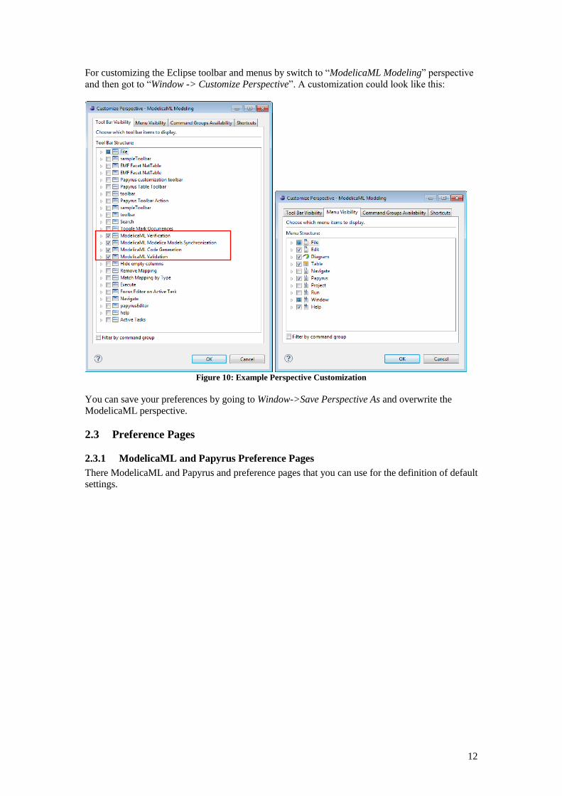
For customizing the Eclipse toolbar and menus by switch to “ModelicaML Modeling” perspective
and then got to “Window -> Customize Perspective”. A customization could look like this:
Figure 10: Example Perspective Customization
You can save your preferences by going to Window->Save Perspective As and overwrite the
ModelicaML perspective.
2.3 Preference Pages
2.3.1 ModelicaML and Papyrus Preference Pages
There ModelicaML and Papyrus and preference pages that you can use for the definition of default
settings.
Page 13
13
Figure 11: ModelicaML and Papyrus Preference Pages
2.3.2 Model Validation Customization
ModelicaML validation is based on EMF Validation Framework [12]. Other plugins may
contribute (constraints) rules for validating the same models elements as are contained in
ModelicaML models. In order to validate your model only according to the ModelicaML
validation rules you should adopt the preferences as shown in the figure below.
Figure 12: Model Validation Preference Pages
Page 14
14
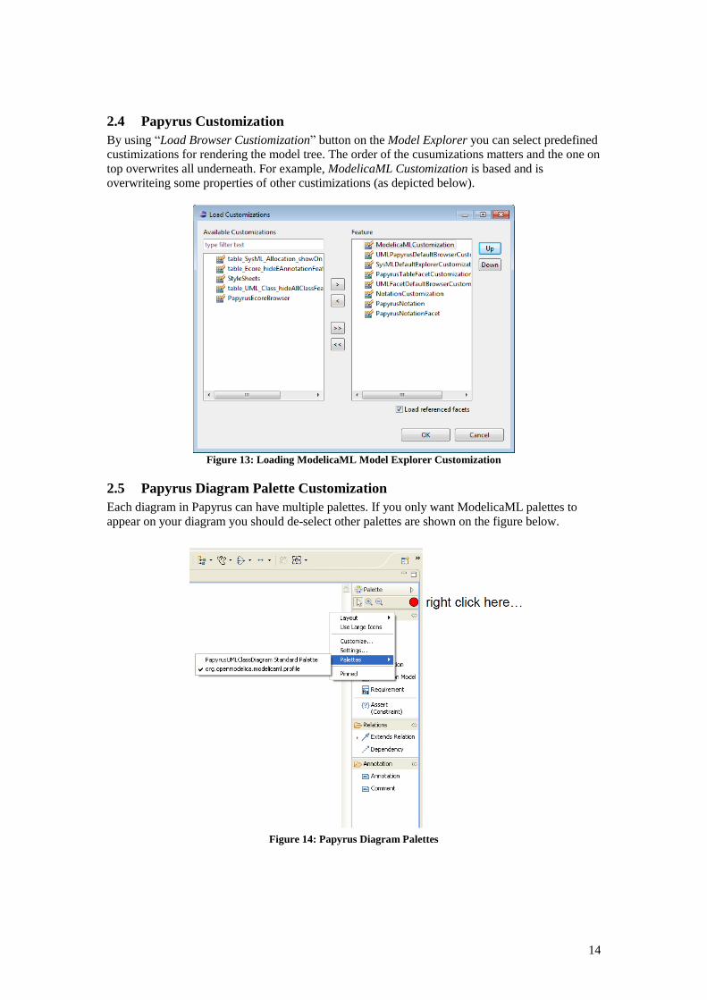
2.4 Papyrus Customization
By using “Load Browser Custiomization” button on the Model Explorer you can select predefined
custimizations for rendering the model tree. The order of the cusumizations matters and the one on
top overwrites all underneath. For example, ModelicaML Customization is based and is
overwriteing some properties of other custimizations (as depicted below).
Figure 13: Loading ModelicaML Model Explorer Customization
2.5 Papyrus Diagram Palette Customization
Each diagram in Papyrus can have multiple palettes. If you only want ModelicaML palettes to
appear on your diagram you should de-select other palettes are shown on the figure below.
Figure 14: Papyrus Diagram Palettes
Page 15
15
3 ModelicaML: Introduction ModelicaML is a graphical modeling language and UML profile for the description of system
architecture and system dynamic behavior. ModelicaML is based on an extended subset of the
OMG Unified Modeling Language (UML) and is designed for Modelica code generation from
graphical models such as state machines and activity diagrams, supporting hardware/software co-
modeling and system requirement verification. ModelicaML is developed in collaboration
between Linköping University and EADS Innovation Works, within the Open Source Modelica
Consortium.
ModelicaML extends the graphical modeling capabilities of Modelica by providing standardized
diagrams for presenting the composition, connection, inheritance, and behavior of system models.
Moreover, ModelicaML incorporates methods for model-based verification of system
requirements using simulations.
Figure 15: ModelicaML concept
The goal of ModelicaML is to enable an efficient and effective way to create, visualize and
maintain combined UML and Modelica models. ModelicaML is defined as a graphical notation
that facilitates different views (e.g., composition, inheritance, behavior) on system models. It is
based on a subset of UML and reuses some concepts from SysML. ModelicaML is designed to
generate Modelica code from graphical models. Since the ModelicaML profile is an extension of
the UML meta-model it can be used as an extension for both UML and SysML2.
UML/SysML provides the modeler with powerful descriptive constructs at the expense of
sometimes loosely defined semantics that are marked as “semantic variation points” in the
UML/SysML specifications. The intention in ModelicaML is to provide the modeler with
powerful executable constructs and precise execution semantics that are based on the Modelica
language. Therefore, ModelicaML uses a subset of UML, extends the UML meta-model (using the
UML profiling mechanism) with new constructs in order to introduce missing Modelica concepts,
and reuses some concepts from SysML. However, like UML and SysML, ModelicaML is mainly
used as a graphical notation. ModelicaML models are eventually translated into Modelica code.
Hence, the ModelicaML execution semantics are defined by the Modelica language and ultimately
by a Modelica compiler that will translate the generated Modelica code into an executable form.
2 SysML itself is also a UML Profile. All ModelicaML stereotypes that extend UML meta-classes are also applicable to the corresponding SysML elements.
Page 16
16
Presently, the ModelicaML prototype is based on the following architecture:
Papyrus [5] is used as modeling tool. It is extended by the ModelicaML profile and
customized modeling tool features (e.g. dedicated toolbars, diagram selections, etc.).
A ModelicaML model can be validated in order to check constraints and possible
inconsistencies by using a validator plug-in which informs the modeler about
inconsistencies or restriction violations. Note that the validation on the ModelicaML
model does not replace the semantic analysis by a Modelica compiler.
The ModelicaML code generator that generates Modelica code from the ModelicaML
models is implemented using the Acceleo Eclipse plug-in [4], which follows the MDA
approach and the model-to-text recommendations of the OMG.
Finally, Modelica tools such as OpenModelica[7], Dymola[8] or MathModelica[9] are
used to load the generated Modelica code and to simulate it.
Figure 16: ModelicaML prototype architecture
Since the ModelicaML profile is an extension of the UML meta-model it can be used for both:
modeling with the standard UML and with the SysML3.
3.1 ModelicaML Notation Overview
The following UML diagrams can be used in ModelicaML for a graphical representation of model
data:
- Class Diagram: for representing inheritance and class decomposition.
- Composite Structure Diagram: for representing class components and their
interconnection. This diagram is similar to the Modelica Connection Diagram.
- Activity Diagram: for modeling of conditional equations or algorithm statements.
- State Machine Diagram: for modeling of state-based behavior.
3 SysML itself is also a UML Profile. All stereotypes that extend UML meta-classes are applicable to the SysML as well.
Page 17
17
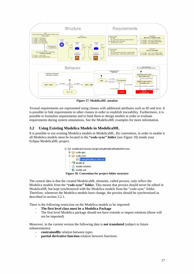
Figure 17: ModelicaML notation
Textual requirements are represented using classes with additional attributes such as ID and text. It
is possible to link requirements to other classes in order to establish traceability. Furthermore, it is
possible to formalize requirements and to bind them to design models in order to evaluate
requirements during system simulations. See the ModelicaML examples for more information.
3.2 Using Existing Modelica Models in ModelicaML
It is possible to use existing Modelica models in ModelicaML. By convention, in order to enable it
all Modelica models must be located in the “code-sync” folder (see Figure 18) inside your
Eclipse ModelicaML project.
Figure 18: Convention for project folder structure
The central idea is that the created ModelicaML elements, called proxies, only reflect the
Modelica models from the “code-sync” folder. This means that proxies should never be edited in
ModelicaML but kept synchronized with the Modelica models from the “code-sync” folder.
Therefore, whenever the Modelica models have change, the proxies should be synchronized as
described in section 3.2.1.
There is the following restriction on the Modelica models to be imported:
- The first level class must be a Modelica Package
- The first level Modelica package should not have extends or import relations (those will
not be imported)
Moreover, in the current version the following data is not translated (subject to future
enhancements):
- contrainedBy relation between types
- partial derivative function relation between functions.
Page 18
18
3.2.1 How to Use It
Alternative 1: To create new proxies or synchronize the Modelica models from the “code-sync”
folder with the existing proxies click on the “Synchronize Modelica Model Proxies” from the
toolbar (see Figure 19) and follow the dialog instructions. For small or mid-size models the
synchronization takes seconds. For large models, such as entire MSL, the synchronization may
take minutes or hours.
Figure 19: Proxy Synchronization toolbar button
Alternative 2: In addition, there is an alternative graphical Eclipse view (see Figure 20) that
provides a tree-based overview of the loaded Modelica models, and has separate actions for
loading and synchronizing proxies. The tree-items are decorated with colored text-style and error
or warning overlay images. These are useful features; however, the current implementation is not
yet efficient in coping with large models. It is not recommended to use the graphical Eclipse view
(from Figure 20) when synchronizing large models such as the entire Modelica Standard Library
(in such a case Alternative 1 from above should be used).
Figure 20: Proxy Synchronization View
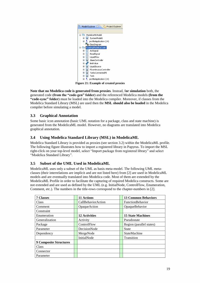
Result: The proxies are created in the ModelicaML model as additional root nodes (see Figure 21)
and can be referenced by other ModelicaML elements.
Page 19
19
Figure 21: Example of created proxies
Note that no Modelica code is generated from proxies. Instead, for simulation both, the
generated code (from the “code-gen” folder) and the referenced Modelica models (from the
“code-sync” folder) must be loaded into the Modelica compiler. Moreover, if classes from the
Modelica Standard Library (MSL) are used then the MSL should also be loaded in the Modelica
compiler before simulating a model.
3.3 Graphical Annotation
Some basic icon annotation (basic UML notation for a package, class and state machine) is
generated from the ModelicaML model. However, no diagrams are translated into Modelica
graphical annotation.
3.4 Using Modelica Standard Library (MSL) in ModelicaML
Modelica Standard Library is provided as proxies (see section 3.2) within the ModelicaML profile.
The following figure illustrates how to import a registered library in Papyrus. To import the MSL
right-click on your top-level model, select “Import package from registered library” and select
“Modelica Standard Library”.
3.5 Subset of the UML Used in ModelicaML
ModelicaML uses only a subset of the UML as basis meta-model. The following UML meta-
classes (their interrelations are implicit and are not listed here) from [2] are used in ModelicaML
models and are eventually translated into Modelica code. Most of them are extended by the
ModelicaML Profile in order to facilitate the capturing of required Modelica constructs. Some are
not extended and are used as defined by the UML (e.g. InitialNode, ControlFlow, Enumeration,
Comment, etc.). The numbers in the title-rows correspond to the chapter-numbers in [2].
7 Classes 11 Actions 13 Common Behaviors
Class CallBehaviorAction FunctionBehavior
Comment OpaqueAction OpaqueBehavior
Constraint
Enumeration 12 Activities 15 State Machines
Generalization Activity Pseudostate
Package ControlFlow Region (parallel states)
Parameter DecisionNode State
Dependency MergeNode StateMachine
InitialNode Transition
9 Composite Structures
Class
Connector
Parameter
Page 20
20
Port
Property
3.5.1 Subset of UML2 Activity Concepts Supported in ModelicaML
A subset of the UML Activity is used in ModelicaML to model conditional equations or algorithm
statements. The only constructs inside an Activity (with respective stereotype applied indicating
that it is an equations or algorithm section) that are supported today are:
- InitialNode (exactly one),
- ControlFlows,
- OpaqueActions (for capturing the assignments or equations),
- CallBehaviorAction (for hierarchical modeling),
- MergeNode and
- DecisionNode (with if/when stereotypes).
Note that the semantic of this sub-set of UML activity is not based on the token-principle. This
notation used for modeling conditional constructs, such as Modelica if or when.
3.5.2 Subset of UML2 State Machines Concepts Supported in ModelicaML
UML defines two types of state machines: Behavior state machines and protocol state machines.
Behavior state machines are used to model parts of class behavior. ModelicaML state machines
are derived from UML behavior state machines. Compared to behavior state machines, protocol
state machines are limited in terms of expressiveness and are tailored to the need to express
protocols or to define the lifecycle of objects. Since this is not the main intended area of
application for ModelicaML, the protocol state machines are not taken into account.
Consequently, none of the chapters of the UML specification that address the protocol state
machines are considered.
3.5.2.1 Support of Graphical Notation
The graphical notation for ModelicaML state machines is based on the notation for UML behavior
state machines. All modeling constructs are supported except SendSignalActions or other actions
(see [2], p.578) which are not supported graphically. Instead the modeler can capture required
behavior in the behavior bodies (e.g., entry/do/exit behavior of states).
3.5.2.2 Supported Subset of UML State Machine Concepts
In the following a list of UML state machine concepts4 is presented which are not supported in
ModelicaML or which are supported in a different way:
15.3.2 FinalState (from BehaviorStateMachines): Supported in ModelicaML. However, no
explicit completion events are generated if regions of a composite state have reached the
FinalStates (see UML[2] p.574, see also comments for “Completion transitions and completion
events” below). Furthermore, no termination of the context object (i.e. class owning the state
machine) is implied if all regions of a composite state reach their FinalStates (see also
comments for terminate state below).
13.3.6 CallEvent (from Communications):
CallEvent implies a call of a class operation. This is not applicable to Modelica since
Modelica does not support the class-method concept that can be found in object-oriented
languages such as Java or C++.
15.3.8 Pseudostate (from BehaviorStateMachines), 15.3.9 PseudostateKind (from
BehaviorStateMachines):
DeepHistory is not supported in ModelicaML.
Terminate: Reaching a terminate state in ModelicaML does not imply termination of the
context object (i.e. class owning the state machine). Reaching a terminate state implies the
deactivation of state machine.
15.3.11 State (from BehaviorStateMachines, ProtocolStateMachines):
4 The chapter numbers correspond to the UML[2] specification chapter numbers.
Page 21
21
Deferred events and State redefinition are not supported in ModelicaML.
15.3.12 StateMachine (from BehaviorStateMachines):
Priority scheme for conflicting transitions that are at different hierarchy levels is different
from UML. UML defines that “The priorities of conflicting transitions are based on their
relative position in the state hierarchy. By definition, a transition originating from a sub
state has higher priority than a conflicting transition originating from any of its containing
states.” UML [2], p. 567). The ModelicaML priority scheme for conflicting transitions is
different.
StateMachine extension is not supported in ModelicaML.
15.3.14 Transition (from BehaviorStateMachines):
Internal (and local) transition are not supported in ModelicaML. Only external transitions
are supported.
Completion transitions and completion events as defined in UML (see p. 574) are not
supported in ModelicaML. The reason for this is that for ModelicaML state machines a
different priority scheme for conflicting transitions (that are at different hierarchy levels) is
used. The same behavior can be expressed in ModelicaML using isInState(…) macro or
joins).
Deferred triggers and Transition redefinition are not supported in ModelicaML.
15.3.15 TransitionKind (from BehaviorStateMachines): Only kind = external is supported in
ModelicaML.
3.5.3 Predefined Macros
The following macros can be used inside transition guard definition or inside the bodies of
entry/do/exit state-actions or transition effects.
3.5.3.1 Macros in Transition Guards
3.5.3.1.1 AFTER - Macro
- Semantic: AFTER() macro is dedicated to state transitions. The meaning is that after a
state is entered and the local state time exceeds the given number this part of the
transition-guard evaluates to true.
- Syntax: AFTER(expression)
- Example: AFTER(23)
- Expanded to: time – state_path.timeAtActivation > 23
3.5.3.1.2 CHANGE - Macro
- Semantic: CHANGE() macro has the same meaning as the Modelica change() function.
- Renamed to: change(variable_name)
3.5.3.1.3 Absolute Value - Macro
- Semantic: Absolute value macro has the same meaning as the Modelica abs() function.
- Syntax: |variable_name|
- Expanded to: abs(variable name)
3.5.3.2 Macros inside Action Bodies
3.5.3.3 GEN_CHANGE - Macro
- Semantic: GEN_CHANGE() is used to negate a Boolean variable.
- Syntax: GEN_CHANGE(name_of_the_boolean_variable)
- Example: GEN_CHANGE(var1)
- Expanded to: name_of_the_boolean_variable := not name_of_the_boolean_variable
Page 22
22
3.6 Limitations
Since ModelicaML is based on the UML meta-model some limitations exist with regard to the
Modelica code to be generated or imported. These limitations are particularly important when
importing existing Modelica code (e.g. Modelica Standard Library) into UML-based (e.g.
ModelicaML) models:
- Graphical Decomposition of Ports (Instances of Connector Classes): In UML it is not
possible to represent Ports decomposition (in ModelicaML these represent instances of
connector classes) graphically.
- Short-Class-Definition: Modelica short-class-definition is not possible in ModelicaML.
The modeler should use inheritance constructs instead.
Page 23
23
References
[1] Modelica Association. Modelica: A Unified Object-Oriented Language for Physical
Systems Modeling: Language Specification Version 3.0, Sept 2007. www.modelica.org
[2] OMG. OMG Unified Modeling Language TM
(OMG UML). Superstructure Version 2.2,
February 2009.
[3] OMG. OMG Systems Modeling Language (OMG SysML™), Version 1.1, November 2008.
[4] Acceleo, Eclipse Plug-In. www.acceleo.org/pages/home/en
[5] Papyrus, www.eclipse.org/modeling/mdt/papyrus/
[6] Schamai W. Modelica Modeling Language (ModelicaML) A UML Profile for Modelica,
Technical Report 2009:5, EADS IW, Germany, Linkoping University, Sweden,
www.ep.liu.se, 2009
[7] The OpenModelica Project www.openmodelica.org
[8] Dymola (Dynamic Modeling Laboratory), Dynamism. www.dymola.com
[9] MathModelica, http://www.mathcore.com
[10] Acceleo, Eclipse Plug-In. www.acceleo.org/pages/home/en
[11] ModelicaML website: www.openmodelica.org/modelicaml
[12] Eclipse Modeling Framework Project (EMF)
http://www.eclipse.org/modeling/emf/?project=validation