24
Modeling a kayak paddle stroke using a Body force Method Joe Banks, Dr Alex Phillips and Prof. Stephen Turnock 6 th OpenFOAM Workshop, Penn State

Modeling a kayak paddle stroke using a Body force Method
Joe Banks, Dr Alex Phillips and Prof. Stephen Turnock6th OpenFOAM Workshop, Penn State

Why simulate a paddle stroke?
• Calculate forces generated by a Paddle.
• Simulate interactions between paddle blade and hull.
• Understand the dynamic forces acting on a kayak.
• Optimise hull and blade design for dynamic race conditions.
2

Why use a body force model?• Self propelled kayak is a complex problem:
• Moving geometries & free surface
• A body force propulsion model simulates the impact of the paddle blade by inducing accelerations in the fluid.
– Removes the need for dynamic mesh.
3
– Reduces cell count and allows for increased time-step as resolution of blade geometry not required.
• Similar method previously used for modelling a ship’s propeller [1].
[1] A.B. Phillips, M.E. Furlong and S.R. Turnock, Accurate capture of rudder-propeller interaction using a coupled blade element momentum-RANS approach. Ship Technology Research (Schiffstechnik), Vol 57, pp 128-139. (2010).

Simple Paddle stroke model
• Angular velocity:
• Advance velocity:
• Radius: r
• Normal velocity on the blade is:
• Therefore the force at a given radius is:
4
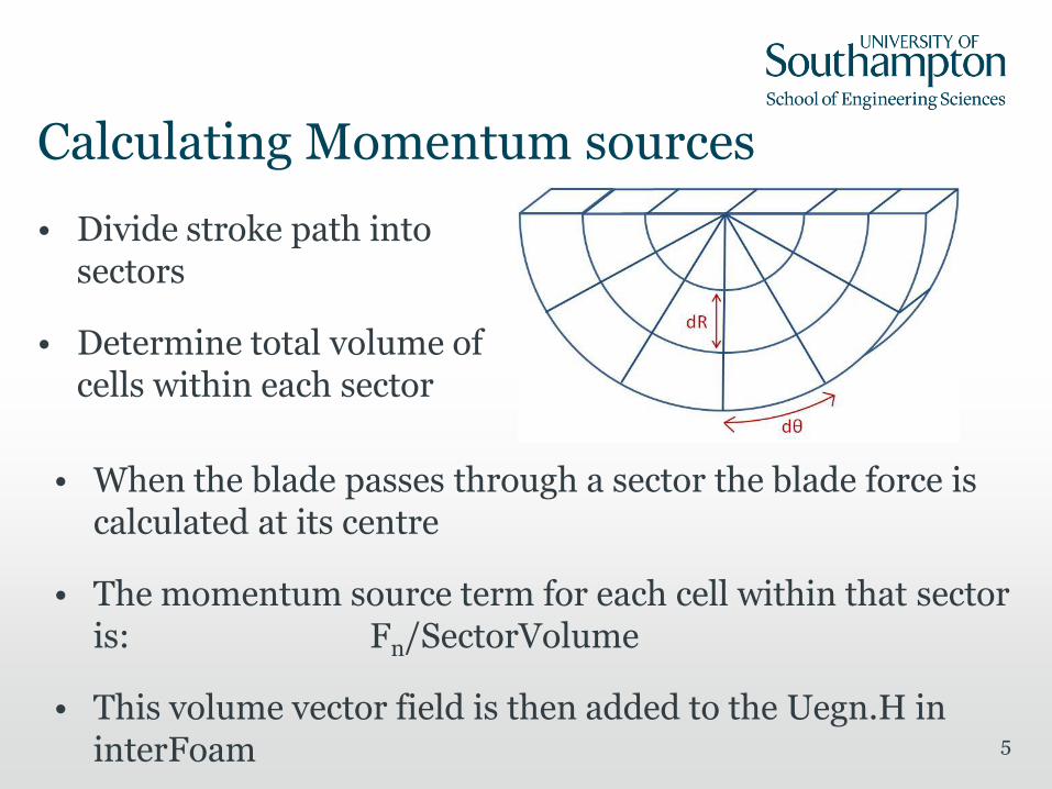
Calculating Momentum sources
• Divide stroke path into sectors
• Determine total volume of cells within each sector
5
• When the blade passes through a sector the blade force is calculated at its centre
• The momentum source term for each cell within that sector is: Fn/SectorVolume
• This volume vector field is then added to the Uegn.H in interFoam

Experimental data for Paddle stroke
6
• Student project performed towing tank tests on a paddle
• Dynamic Swing test applied a constant torque via a dropping weight
• Blade angle and Horizontal forces (Thrust & Side force) measured using towing Tank Dynamometer
• Various angles of attack

Experimental data for Paddle stroke
7

Comparing simple blade model to experimental data
8
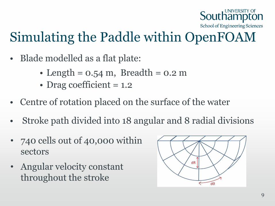
Simulating the Paddle within OpenFOAM
• Blade modelled as a flat plate:
• Length = 0.54 m, Breadth = 0.2 m
• Drag coefficient = 1.2
• Centre of rotation placed on the surface of the water
• Stroke path divided into 18 angular and 8 radial divisions
9
• 740 cells out of 40,000 within sectors
• Angular velocity constant throughout the stroke

Thrust generated at a constant RPM
10

Thrust generated for varying RPM
11

Improvements needed for paddle model
• Unsteady effects:
• Added mass due to acceleration
• Changes in thrust due to Vortex generation
12
• Affects of radial flow on the blade
• In the meantime increase drag coefficient to match experimental data

Thrust generated for modified Cd
13

Simulating a self-propelled kayak
14

Naked hull resistance• Advance speed = 2m/s
• L=4m, B=0.6m, D=0.25m
15
Property MeshType of mesh Unstructured (Hexahedral)
No. of elements Approximately 1.2M
y+ on the hull 10-15
Domain PhysicsHomogeneous Water/Air
multiphase, kOmegaSST turbulence model, Automatic wall function
Boundary physics:Inlet Free stream velocity
Outlet Zero gradient
Bottom/side wall Wall with free stream velocity
Top OpeningHull Wall with no slip condition
Solver settings:Transient scheme 1st order EulerGrad (U) Scheme Gauss linear
Div (U) Gauss limitedLinearV 1Pressure coupling PISO
Convergence criteriaP 1e-7, U 1e-6, k 1e-8, omega 1e-8
Multiphase control Volume fraction couplingTimestep control max Courant No = 0.4
Processing Parameters:
Computing System
Iridis 3 Linux Cluster (University of Southampton)
Run typeParallel (9 - 24 Partitions run on 5x8 core nodes each with 23 Gb RAM)
Bow Stern

Naked hull resistance 22.68 N
16

Determine Required Stroke Rate
17
• Vary angular velocity throughout stroke to approximate a constant Torque Condition.
• Average thrust over half a stroke cycle =22.60 N

Self Propelled Simulation
• Continued run from naked hull case
• Applied two paddle models, one on each side but out of phase, with their centre of rotation 0.5 m from hull centre line.
• Naked hull resistance = 22.68 N
• Average Thrust over = 22.60 N
18

Paddle Induced Velocities 0.5m from hull
19

Pressure on hull during Left paddle stroke
20

Forces acting on the hull during paddle strokes
21
Right (+) Left (-) Left (-)Right (+)
Average self Propelled resistance = 21.5 (N)

Moments acting on the hull during paddle strokes
22
Right (+) Right (+)Left (-) Left (-)

Conclusion
• A simple methodology has been developed for investigating the paddle and hull interaction in kayaking.
• To allow more realistic stroke techniques to be modelled a more sophisticated paddle model needs to be developed including:
• Unsteady 3D effects on force coefficients,
• Lift and drag forces for varying angles of attack,
• Generic stroke paths allowing translation and rotation
23

Thank you for listening?
Are there any questions?
24


