JOURNAL OF THEORETICAL AND APPLIED MECHANICS 55, 1, pp. 213-226, Warsaw 2017 DOI: 10.15632/jtam-pl.55.1.213 MODELING AND ANALYSIS OF COUPLED FLEXURAL-TORSIONAL SPINNING BEAMS WITH UNSYMMETRICAL CROSS SECTIONS Jie Wang, Dongxu Li, Jianping Jiang College of Aerospace Science and Engineering, National University of Defense Technology, Changsha, China e-mail: [email protected]The structural modeling and dynamic properties of a spinning beam with an unsymmetri- cal cross section are studied. Due to the eccentricity and spinning, transverse deflections along the two principal directions and the torsional motion about the longitudinal axis are coupled. The structural model of the beam is established based on the Hamilton principle and by incorporating the torsional inertia. Moreover, because of its significant influence on characteristics for the non-circular cross-sectional beam, the warping effect is considered in the formulation. The proposed model is effectively validated in two cases: the spinning be- am with a symmetric cross section and the cantilevered beam with an unsymmetrical cross section. Then the effects of the spinning speed on natural frequencies and mode shapes are investigated. Numerical results reveal that the critical speed is altered with respect to nonco- incidence of the centroid and the shear center. For the beams with strong warping rigidities, the warping effect cannot be neglected due to significant influence on natural frequencies. Keywords: spinning beam, critical speed, warping, coupled flexural-torsional vibration 1. Introduction Spinning beams are important components of turbine blades, propellers, elastic linkages, satellite booms and are widespread in various branches of structural engineering. Dynamic characteristics such as natural frequencies and mode shapes of these systems are meaningful for analysis of position accuracy, throughput, fatigue and safety. As a consequence, it is essential to accurately establish the dynamic model of spinning beams and predict its vibration characteristics. For the last decades, there has been a growing interest in the investigation of structural modeling, and excellent work has been done on the dynamic analysis of spinning beams. The fully flexural-torsional coupling model for spinning beams has been successfully established based on the analytical method by Bishop (1959), Dimentberg (1961), Kane (1961), Newland (1972) and Zu and Han (1992). Bishop (1959) utilized Newton’s method to derive the characteristic equation of a bent shaft in the Euler-Bernoulli beam model and investigated the stability of the system. Lagrangian approach (Shiau et al., 2006) and Hamilton’s principle (Yoon and Kim, 2002) were also utilized to derive the governing equations for the system. Besides, different methods were proposed by researchers in order to solve the governing equations, i.e. assumed- -modes method, finite element method, and dynamic stiffness method. Shiau et al. (2006) studied the dynamic behavior of a spinning Timoshenko beam with general boundary conditions based on the global assumed mode method. Yoon and Kim (2002) utilized the finite element method to analyze the dynamic stability of an unconstrained spinning beam subjected to a pulsating follower force. Banerjee and Su (2004) developed the dynamic stiffness method and the Wittrick- -Williams algorithm was applied to compute natural frequencies and mode shapes. This method was also used in the free vibration analysis of a spinning composite beam (Banerjee and Su, 2006).
Transcript
JOURNAL OF THEORETICAL
AND APPLIED MECHANICS
55, 1, pp. 213-226, Warsaw 2017DOI: 10.15632/jtam-pl.55.1.213
MODELING AND ANALYSIS OF COUPLED FLEXURAL-TORSIONAL
SPINNING BEAMS WITH UNSYMMETRICAL CROSS SECTIONS
Jie Wang, Dongxu Li, Jianping Jiang
College of Aerospace Science and Engineering, National University of Defense Technology, Changsha, China
The structural modeling and dynamic properties of a spinning beam with an unsymmetri-cal cross section are studied. Due to the eccentricity and spinning, transverse deflectionsalong the two principal directions and the torsional motion about the longitudinal axis arecoupled. The structural model of the beam is established based on the Hamilton principleand by incorporating the torsional inertia. Moreover, because of its significant influence oncharacteristics for the non-circular cross-sectional beam, the warping effect is considered inthe formulation. The proposed model is effectively validated in two cases: the spinning be-am with a symmetric cross section and the cantilevered beam with an unsymmetrical crosssection. Then the effects of the spinning speed on natural frequencies and mode shapes areinvestigated. Numerical results reveal that the critical speed is altered with respect to nonco-incidence of the centroid and the shear center. For the beams with strong warping rigidities,the warping effect cannot be neglected due to significant influence on natural frequencies.
Spinning beams are important components of turbine blades, propellers, elastic linkages, satellitebooms and are widespread in various branches of structural engineering. Dynamic characteristicssuch as natural frequencies and mode shapes of these systems are meaningful for analysis ofposition accuracy, throughput, fatigue and safety. As a consequence, it is essential to accuratelyestablish the dynamic model of spinning beams and predict its vibration characteristics.
For the last decades, there has been a growing interest in the investigation of structuralmodeling, and excellent work has been done on the dynamic analysis of spinning beams. Thefully flexural-torsional coupling model for spinning beams has been successfully established basedon the analytical method by Bishop (1959), Dimentberg (1961), Kane (1961), Newland (1972)and Zu and Han (1992). Bishop (1959) utilized Newton’s method to derive the characteristicequation of a bent shaft in the Euler-Bernoulli beam model and investigated the stability ofthe system. Lagrangian approach (Shiau et al., 2006) and Hamilton’s principle (Yoon and Kim,2002) were also utilized to derive the governing equations for the system. Besides, differentmethods were proposed by researchers in order to solve the governing equations, i.e. assumed--modes method, finite element method, and dynamic stiffness method. Shiau et al. (2006) studiedthe dynamic behavior of a spinning Timoshenko beam with general boundary conditions basedon the global assumed mode method. Yoon and Kim (2002) utilized the finite element methodto analyze the dynamic stability of an unconstrained spinning beam subjected to a pulsatingfollower force. Banerjee and Su (2004) developed the dynamic stiffness method and the Wittrick--Williams algorithm was applied to compute natural frequencies and mode shapes. This methodwas also used in the free vibration analysis of a spinning composite beam (Banerjee and Su,2006).
214 J. Wang et al.
Based on the proposed methods, many researchers dealt with problems of spinning beamssubjected to different kinds of loads (Ho and Chen, 2006; Lee, 1995; Zu and Han, 1994) undervarious boundary conditions (Choi et al., 2000; Zu and Melanson, 1998). Sheu and Yang (2005)studied the dynamic response of a spinning Rayleigh beam with rotary inertia and gyroscopiceffects in general boundary conditions. The relationship between the critical speed and thehollowness ratio and length-to-radius ratio was investigated by Sheu (2007). Ouyang and Wang(2007) presented a dynamic model for vibration of a rotating Timoshenko beam subjected to athree-directional load moving in the axial direction. Popplewell and Chang (1997) investigatedfree vibrations of a simply supported but stepped spinning Timoshenko beam with the Galerkinmethod. Ho and Chen (2006) discussed the vibration problems of a spinning axially loadedpre-twisted Timoshenko beam. Na et al. (2006) established the model of a tapered thin-walledcomposite spinning beam subjected to an axial compressive force. Moreover, dynamic stabilityof spinning structures around the longitudinal axis such as a shaft or an unconstrained beamhas been widely investigated (Lee, 1996; Tylikowski, 2008). Experimental investigations on acantilevered spinning shaft have been reported. Qian et al. (2010) conducted a non-contactdynamic testing of a highly flexible spinning vertical shaft.
In all of these studies, spinning beams had symmetric cross-sections and the shear center andcentroid were assumed to superpose each other. In practical applications, the cross-section of thespinning beam can be eccentric due to errors during processing. Moreover, in some circumstancesthe cross-section is intended to be eccentric to meet the requirement of the engineering. For abeam with an arbitrary uniform cross section, the coupling of bending and torsion may occurwhen the beam experiences rotating motion. Yoo and Shin (1998) studied the eigenvalue lociveerings and mode shape variations for a rotating cantilever beam with the coupling effectconsidered. Latalski et al. (2014) investigated a rotating composite beam with piezoelectric activeelements. An analysis of a rotor with several flexible blades was conducted with the spin softeningeffects and the centrifugal stiffening effects considered through a pre-stressed potential (Lesaffreet al., 2007). Sinha and Turner (2011) further researched the characteristics of a rotating pre-twisted blade. In these studies, the direction of rotation is vertical to the longitudinal direction.Literature focused on the analysis of a beam rotating about its longitudinal direction is few.Filipich et al. (1987) studied the free vibration coupling of bending and torsion of a uniformspinning beam having one axis of symmetry. Then they extended the approach to a beam havingno symmetric axis and developed a dynamic model of coupled torsional an bending deformations(Filipich and Rosales, 1990). The model accounted for the dynamic coupling terms due to therotation and the eccentricity.
This paper further discusses the bending-torsion coupling effects with the warping effectconsidered. Natural characteristics including natural frequencies and mode shapes with respectto the spinning velocity and the eccentricity are investigated. And the critical spinning speedvariation is observed in the presence of coupling effects. The paper is organized as follows. InSection 2, differential equations of the beam are formulated based on the Hamilton principle.The formulations are built on Euler-Bernoulli beam theory with the warping effect and torsionalrigidity while neglecting the effect of shear rigidities. In Section 3, we calculate mode shapefunctions and natural frequencies of the system by applying the assumed mode method. InSection 4, the present model is validated by comparing with literature and numerically simulatedwith examples. The effects of spinning speed and warping on natural frequencies, mode shapesand critical speed are examined.
2. Governing differential equations
This Section deals with the formulation of differential equations for a spinning beam with anarbitrary cross section based on Hamilton’s principle.
Modeling and analysis of coupled flexural-torsional spinning beams... 215
2.1. System description
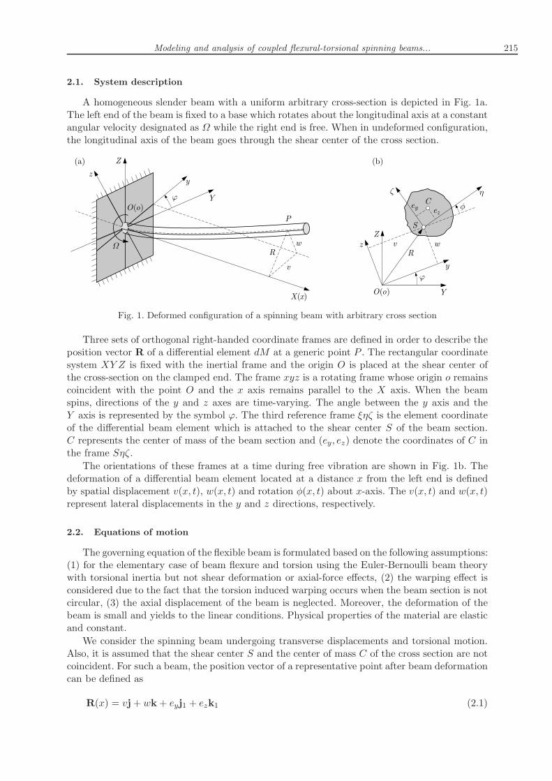
A homogeneous slender beam with a uniform arbitrary cross-section is depicted in Fig. 1a.The left end of the beam is fixed to a base which rotates about the longitudinal axis at a constantangular velocity designated as Ω while the right end is free. When in undeformed configuration,the longitudinal axis of the beam goes through the shear center of the cross section.
Fig. 1. Deformed configuration of a spinning beam with arbitrary cross section
Three sets of orthogonal right-handed coordinate frames are defined in order to describe theposition vector R of a differential element dM at a generic point P . The rectangular coordinatesystem XY Z is fixed with the inertial frame and the origin O is placed at the shear center ofthe cross-section on the clamped end. The frame xyz is a rotating frame whose origin o remainscoincident with the point O and the x axis remains parallel to the X axis. When the beamspins, directions of the y and z axes are time-varying. The angle between the y axis and theY axis is represented by the symbol ϕ. The third reference frame ξηζ is the element coordinateof the differential beam element which is attached to the shear center S of the beam section.C represents the center of mass of the beam section and (ey, ez) denote the coordinates of C inthe frame Sηζ.
The orientations of these frames at a time during free vibration are shown in Fig. 1b. Thedeformation of a differential beam element located at a distance x from the left end is definedby spatial displacement v(x, t), w(x, t) and rotation φ(x, t) about x-axis. The v(x, t) and w(x, t)represent lateral displacements in the y and z directions, respectively.
2.2. Equations of motion
The governing equation of the flexible beam is formulated based on the following assumptions:(1) for the elementary case of beam flexure and torsion using the Euler-Bernoulli beam theorywith torsional inertia but not shear deformation or axial-force effects, (2) the warping effect isconsidered due to the fact that the torsion induced warping occurs when the beam section is notcircular, (3) the axial displacement of the beam is neglected. Moreover, the deformation of thebeam is small and yields to the linear conditions. Physical properties of the material are elasticand constant.
We consider the spinning beam undergoing transverse displacements and torsional motion.Also, it is assumed that the shear center S and the center of mass C of the cross section are notcoincident. For such a beam, the position vector of a representative point after beam deformationcan be defined as
R(x) = vj+ wk+ eyj1 + ezk1 (2.1)
216 J. Wang et al.
where i, j and k are unit vectors in the x, y and z directions, respectively. And i1, j1 and k1 areunit vectors in the ξ, η and ζ directions, respectively.The velocity of the point can be obtained as follows
The symbols ρ, E and A denote density, Young’s modulus and cross sectional area. Jp is thepolar moment of inertia and is given by
Jp =
∫∫
A
r2p dη dζ (2.4)
where rp represents the distance between a certain point in the section and the center.The potential strain energy of the beam including the warping effect is considered as below
U =1
2
L∫
0
E(Izv′′2 + Iyw
′′2) dx+1
2
L∫
0
GJpφ′2 dx+
1
2
L∫
0
EΓφ′′2dx (2.5)
where G denotes the shear modulus. Iy and Iz show the second moments of area about thez-axis and y-axis, EΓ is warping rigidity. Primes denote partial derivatives with respect to x.For uniform beams, A, Iy, Iz, Jp and EΓ are constant throughout the span.Then the Lagrangian function of the beam system can be expressed as
L = T − U =1
2
L∫
0
ρA(v2 + w2) dx+1
2
L∫
0
ρA[Ω2(v2 + w2)− 2Ωvw + 2Ωvw] dx
+1
2ρJp
L∫
0
φ2 dx+1
2
L∫
0
ρA(e2φ2 − 2ez vφ+ 2eywφ+ 2ezΩwφ+ 2eyΩvφ) dx
+
L∫
0
ρA(e2Ωφ− ezΩv + ezΩ2w + eyΩw + eyΩ2v) dx
+
L∫
0
ρA(−eyΩvφ+ eyΩ2wφ− ezΩwφ− ezΩ2vφ) dx+1
2
L∫
0
ρAe2Ω2 dx
−1
2
L∫
0
E(Izv′′2 + Iyw
′′2) dx−1
2
L∫
0
GJpφ′2 dx−
1
2
L∫
0
EΓφ′′2dx
(2.6)
Modeling and analysis of coupled flexural-torsional spinning beams... 217
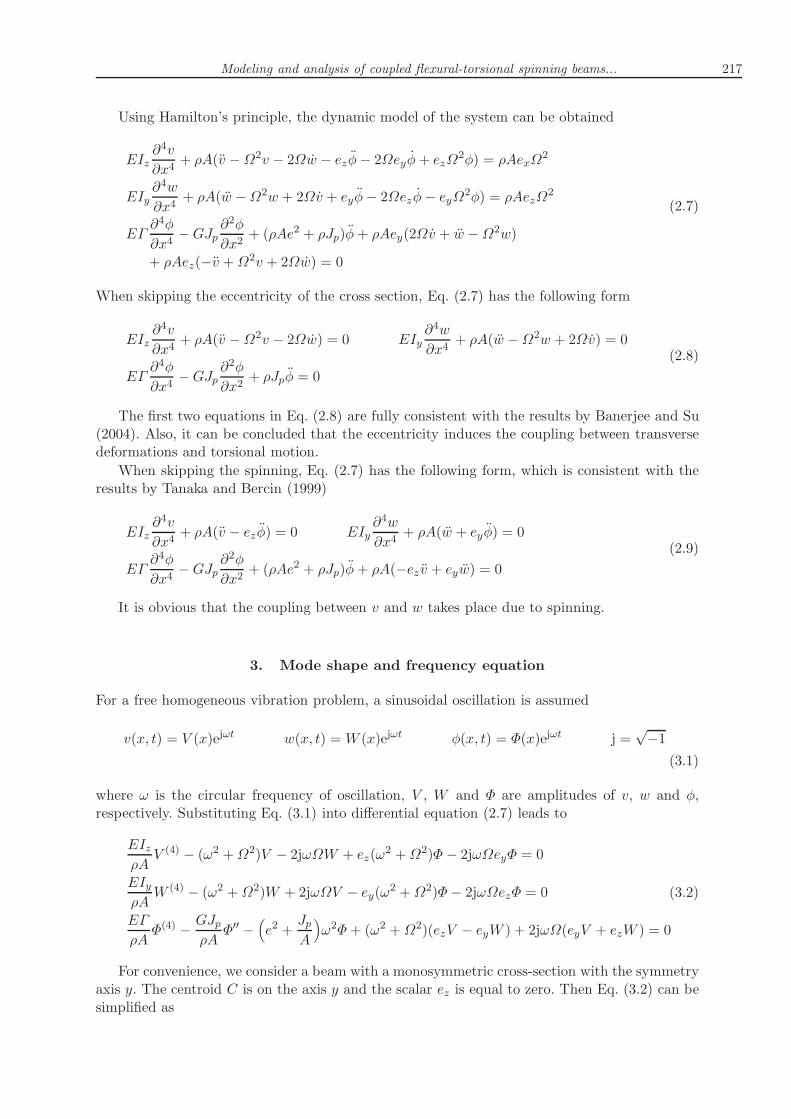
Using Hamilton’s principle, the dynamic model of the system can be obtained
When skipping the eccentricity of the cross section, Eq. (2.7) has the following form
EIz∂4v
∂x4+ ρA(v −Ω2v − 2Ωw) = 0 EIy
∂4w
∂x4+ ρA(w −Ω2w + 2Ωv) = 0
EΓ∂4φ
∂x4−GJp
∂2φ
∂x2+ ρJpφ = 0
(2.8)
The first two equations in Eq. (2.8) are fully consistent with the results by Banerjee and Su(2004). Also, it can be concluded that the eccentricity induces the coupling between transversedeformations and torsional motion.
When skipping the spinning, Eq. (2.7) has the following form, which is consistent with theresults by Tanaka and Bercin (1999)
EIz∂4v
∂x4+ ρA(v − ezφ) = 0 EIy
∂4w
∂x4+ ρA(w + eyφ) = 0
EΓ∂4φ
∂x4−GJp
∂2φ
∂x2+ (ρAe2 + ρJp)φ+ ρA(−ez v + eyw) = 0
(2.9)
It is obvious that the coupling between v and w takes place due to spinning.
3. Mode shape and frequency equation
For a free homogeneous vibration problem, a sinusoidal oscillation is assumed
where ω is the circular frequency of oscillation, V , W and Φ are amplitudes of v, w and φ,respectively. Substituting Eq. (3.1) into differential equation (2.7) leads to
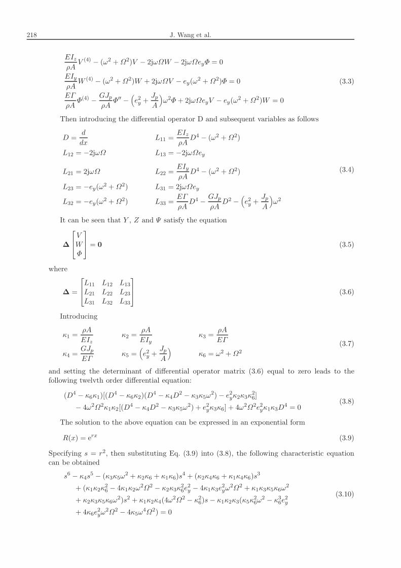
For convenience, we consider a beam with a monosymmetric cross-section with the symmetryaxis y. The centroid C is on the axis y and the scalar ez is equal to zero. Then Eq. (3.2) can besimplified as
218 J. Wang et al.
EIz
ρAV (4) − (ω2 +Ω2)V − 2jωΩW − 2jωΩeyΦ = 0
EIy
ρAW (4) − (ω2 +Ω2)W + 2jωΩV − ey(ω2 +Ω2)Φ = 0
EΓ
ρAΦ(4) −
GJp
ρAΦ′′ −
(
e2y +Jp
A
)
ω2Φ+ 2jωΩeyV − ey(ω2 +Ω2)W = 0
(3.3)
Then introducing the differential operator D and subsequent variables as follows
D =d
dxL11 =
EIz
ρAD4 − (ω2 +Ω2)
L12 = −2jωΩ L13 = −2jωΩey
L21 = 2jωΩ L22 =EIy
ρAD4 − (ω2 +Ω2)
L23 = −ey(ω2 +Ω2) L31 = 2jωΩey
L32 = −ey(ω2 +Ω2) L33 =EΓ
ρAD4 −
GJp
ρAD2 −
(
e2y +Jp
A
)
ω2
(3.4)
It can be seen that Y , Z and Ψ satisfy the equation
∆
V
W
Φ
= 0 (3.5)
where
∆ =
L11 L12 L13L21 L22 L23L31 L32 L33
(3.6)
Introducing
κ1 =ρA
EIzκ2 =
ρA
EIyκ3 =
ρA
EΓ
κ4 =GJp
EΓκ5 =
(
e2y +Jp
A
)
κ6 = ω2 +Ω2
(3.7)
and setting the determinant of differential operator matrix (3.6) equal to zero leads to thefollowing twelvth order differential equation:
Modeling and analysis of coupled flexural-torsional spinning beams... 219
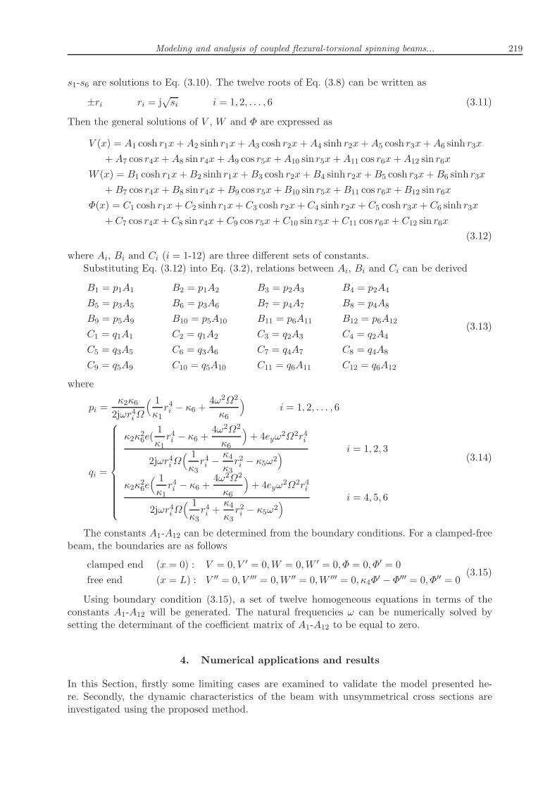
s1-s6 are solutions to Eq. (3.10). The twelve roots of Eq. (3.8) can be written as
±ri ri = j√si i = 1, 2, . . . , 6 (3.11)
Then the general solutions of V , W and Φ are expressed as
V (x) = A1 cosh r1x+A2 sinh r1x+A3 cosh r2x+A4 sinh r2x+A5 cosh r3x+A6 sinh r3x
+A7 cos r4x+A8 sin r4x+A9 cos r5x+A10 sin r5x+A11 cos r6x+A12 sin r6x
W (x) = B1 cosh r1x+B2 sinh r1x+B3 cosh r2x+B4 sinh r2x+B5 cosh r3x+B6 sinh r3x
+B7 cos r4x+B8 sin r4x+B9 cos r5x+B10 sin r5x+B11 cos r6x+B12 sin r6x
Φ(x) = C1 cosh r1x+C2 sinh r1x+ C3 cosh r2x+ C4 sinh r2x+ C5 cosh r3x+ C6 sinh r3x
+ C7 cos r4x+ C8 sin r4x+ C9 cos r5x+ C10 sin r5x+ C11 cos r6x+ C12 sin r6x
(3.12)
where Ai, Bi and Ci (i = 1-12) are three different sets of constants.Substituting Eq. (3.12) into Eq. (3.2), relations between Ai, Bi and Ci can be derived
B1 = p1A1 B2 = p1A2 B3 = p2A3 B4 = p2A4
B5 = p3A5 B6 = p3A6 B7 = p4A7 B8 = p4A8
B9 = p5A9 B10 = p5A10 B11 = p6A11 B12 = p6A12
C1 = q1A1 C2 = q1A2 C3 = q2A3 C4 = q2A4
C5 = q3A5 C6 = q3A6 C7 = q4A7 C8 = q4A8
C9 = q5A9 C10 = q5A10 C11 = q6A11 C12 = q6A12
(3.13)
where
pi =κ2κ6
2jωr4iΩ
( 1
κ1r4i − κ6 +
4ω2Ω2
κ6
)
i = 1, 2, . . . , 6
qi =
κ2κ26e(1
κ1r4i − κ6 +
4ω2Ω2
κ6
)
+ 4eyω2Ω2r4i
2jωr4iΩ( 1
κ3r4i −κ4
κ3r2i − κ5ω2
)
i = 1, 2, 3
κ2κ26e( 1
κ1r4i − κ6 +
4ω2Ω2
κ6
)
+ 4eyω2Ω2r4i
2jωr4iΩ( 1
κ3r4i +κ4
κ3r2i − κ5ω2
)
i = 4, 5, 6
(3.14)
The constants A1-A12 can be determined from the boundary conditions. For a clamped-freebeam, the boundaries are as follows
clamped end (x = 0) : V = 0, V ′ = 0,W = 0,W ′ = 0, Φ = 0, Φ′ = 0
free end (x = L) : V ′′ = 0, V ′′′ = 0,W ′′ = 0,W ′′′ = 0, κ4Φ′ − Φ′′′ = 0, Φ′′ = 0
(3.15)
Using boundary condition (3.15), a set of twelve homogeneous equations in terms of theconstants A1-A12 will be generated. The natural frequencies ω can be numerically solved bysetting the determinant of the coefficient matrix of A1-A12 to be equal to zero.
4. Numerical applications and results
In this Section, firstly some limiting cases are examined to validate the model presented he-re. Secondly, the dynamic characteristics of the beam with unsymmetrical cross sections areinvestigated using the proposed method.
220 J. Wang et al.
4.1. Validation
The example for validating is taken from literature (Banerjee and Su, 2004). The beam hasa rectangular cross section and possesses equal flexural rigidities in the two principal directionsof the cross section. The properties are given by: EIyy = 582.996 Nm
2, EIzz = 582.996 Nm2,
ρA = 2.87 kg/m, L = 1.29m.The non-dimensional natural frequency and the spinning speed parameter are defined as in
literature (Banerjee and Su, 2004)
ω∗i =ωi
ω0Ω∗ =
Ω
ω0(4.1)
where
ω0 =
√
√
EIyyEIzz
ρAL4(4.2)
Comparison of the first three natural frequencies in the current study with those given inpublished literature is listed in Table 1. Both examples apply to cantilever end conditions, andthe effect of warping stiffness is excluded in the analysis. It is concluded that the resultingfrequencies are in good agreement with the one given in the previous work. Because EIyy equalsEIzz in this example, the natural frequency parameters of the first two modes are equal whenthe spinning speed parameter is zero.
Table 1. Natural frequencies of the spinning beam: (1) Banerjee and Su (2004), (2) presentmethod
Spinning Natural frequency parameters (ω∗i )speed ω∗1 ω∗2 ω∗3
parameter (Ω∗) (1) (2) (1) (2) (1) (2)
0 3.516 3.516 3.516 3.516 22.034 22.034
2 1.516 1.516 5.516 5.516 24.034 24.034
3.5 0 0 7.016 7.016 25.534 25.534
4 – – 7.516 7.516 26.034 26.034
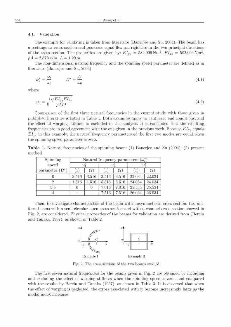
Then, to investigate characteristics of the beam with unsymmetrical cross section, two uni-form beams with a semi-circular open cross section and with a channel cross section showed inFig. 2, are considered. Physical properties of the beams for validation are derived from (Bercinand Tanaka, 1997), as shown in Table 2.
Fig. 2. The cross sections of the two beams studied
The first seven natural frequencies for the beams given in Fig. 2 are obtained by includingand excluding the effect of warping stiffness when the spinning speed is zero, and comparedwith the results by Bercin and Tanaka (1997), as shown in Table 3. It is observed that whenthe effect of warping is neglected, the errors associated with it become increasingly large as themodal index increases.
Modeling and analysis of coupled flexural-torsional spinning beams... 221
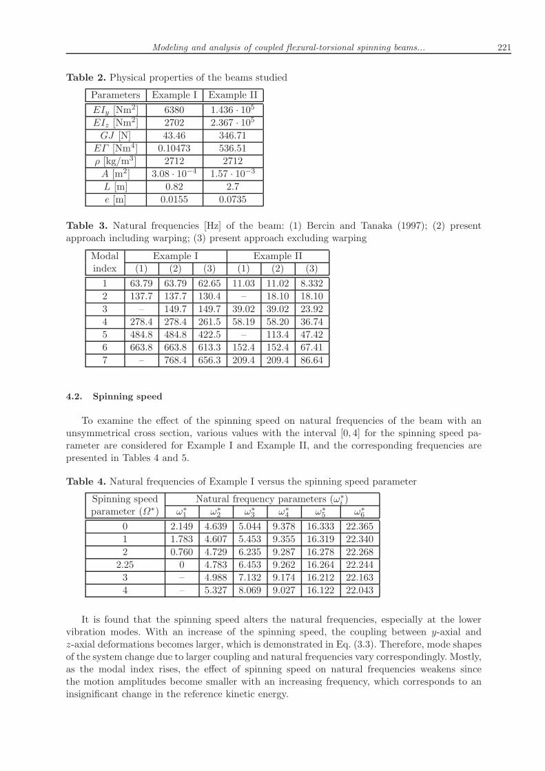
Table 2. Physical properties of the beams studied
Parameters Example I Example II
EIy [Nm2] 6380 1.436 · 105
EIz [Nm2] 2702 2.367 · 105
GJ [N] 43.46 346.71
EΓ [Nm4] 0.10473 536.51
ρ [kg/m3] 2712 2712
A [m2] 3.08 · 10−4 1.57 · 10−3L [m] 0.82 2.7
e [m] 0.0155 0.0735
Table 3. Natural frequencies [Hz] of the beam: (1) Bercin and Tanaka (1997); (2) presentapproach including warping; (3) present approach excluding warping
Modal Example I Example IIindex (1) (2) (3) (1) (2) (3)
1 63.79 63.79 62.65 11.03 11.02 8.332
2 137.7 137.7 130.4 – 18.10 18.10
3 – 149.7 149.7 39.02 39.02 23.92
4 278.4 278.4 261.5 58.19 58.20 36.74
5 484.8 484.8 422.5 – 113.4 47.42
6 663.8 663.8 613.3 152.4 152.4 67.41
7 – 768.4 656.3 209.4 209.4 86.64
4.2. Spinning speed
To examine the effect of the spinning speed on natural frequencies of the beam with anunsymmetrical cross section, various values with the interval [0, 4] for the spinning speed pa-rameter are considered for Example I and Example II, and the corresponding frequencies arepresented in Tables 4 and 5.
Table 4. Natural frequencies of Example I versus the spinning speed parameter
It is found that the spinning speed alters the natural frequencies, especially at the lowervibration modes. With an increase of the spinning speed, the coupling between y-axial andz-axial deformations becomes larger, which is demonstrated in Eq. (3.3). Therefore, mode shapesof the system change due to larger coupling and natural frequencies vary correspondingly. Mostly,as the modal index rises, the effect of spinning speed on natural frequencies weakens sincethe motion amplitudes become smaller with an increasing frequency, which corresponds to aninsignificant change in the reference kinetic energy.
222 J. Wang et al.
Table 5. Natural frequencies of Example II versus the spinning speed parameter
Figures 3a and 3b show variations of the first four non-dimensional natural frequencies withrespect to the spinning speed parameter. Because of the large difference between the bendingrigidities in the two principal planes, the natural frequencies start off with different values. Thefundamental frequencies of both examples decrease with the increasing spinning speed while theothers decrease or increase. At a certain spinning speed, which is defined as the critical speed,the first natural frequency becomes negative, resulting in instability. For the spinning beamwith circular or rectangular cross-section, the natural frequencies are obtained by subtracting oradding the natural frequencies when Ω∗ = 0 to the spinning speed parameter (Banerjee and Su,2004). So the value of the critical spinning speed when the beam becomes unstable equals to thefirst frequency of the beam with Ω∗ = 0. For the spinning beam with an unsymmetrical cross-section, the noncoincidence of mass center and shear center induces coupled flexural-torsionalmodes and alters the critical speed. Both values of the critical speed are larger than the firstfrequencies for the examples studied.
Fig. 3. Natural frequencies versus the spinning speed for (a) Example I, (b) Example II
4.3. Warping effect
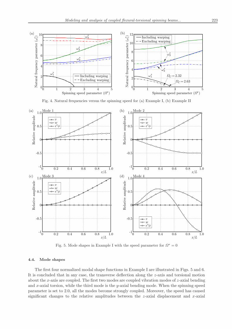
The relative errors of natural frequencies due to the warping effect are discussed in thisSection. Figures 4a and 4b show changes of natural frequencies with respect to the spinningspeed with inclusion and exclusion of the warping for Example I and II, respectively.
It is evident that the inclusion of the warping effect increases the natural frequencies. Andwhen the warping effect is neglected, the errors associated with it become increasingly larger asthe modal index increases. Additionally, errors in Example II are more severe than in Example I.This is because the proportion of warping rigidity to bending rigidity in Example II is largerthan that in Example I. It is also observed that the exclusion of warping makes the critical speeddecrease.
Modeling and analysis of coupled flexural-torsional spinning beams... 223
Fig. 4. Natural frequencies versus the spinning speed for (a) Example I, (b) Example II
Fig. 5. Mode shapes in Example I with the speed parameter for Ω∗ = 0
4.4. Mode shapes
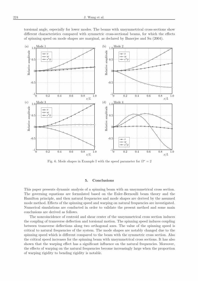
The first four normalized modal shape functions in Example I are illustrated in Figs. 5 and 6.It is concluded that in any case, the transverse deflection along the z-axis and torsional motionabout the x-axis are coupled. The first two modes are coupled vibration modes of z-axial bendingand x-axial torsion, while the third mode is the y-axial bending mode. When the spinning speedparameter is set to 2.0, all the modes become strongly coupled. Moreover, the speed has causedsignificant changes to the relative amplitudes between the z-axial displacement and x-axial
224 J. Wang et al.
torsional angle, especially for lower modes. The beams with unsymmetrical cross-sections showdifferent characteristics compared with symmetric cross-sectional beams, for which the effectsof spinning speed on mode shapes are marginal, as declared by Banerjee and Su (2004).
Fig. 6. Mode shapes in Example I with the speed parameter for Ω∗ = 2
5. Conclusions
This paper presents dynamic analysis of a spinning beam with an unsymmetrical cross section.The governing equations are formulated based on the Euler-Bernoulli beam theory and theHamilton principle, and then natural frequencies and mode shapes are derived by the assumedmode method. Effects of the spinning speed and warping on natural frequencies are investigated.Numerical simulations are conducted in order to validate the present method and some mainconclusions are derived as follows.
The noncoincidence of centroid and shear center of the unsymmetrical cross section inducesthe coupling of transverse deflection and torsional motion. The spinning speed induces couplingbetween transverse deflections along two orthogonal axes. The value of the spinning speed iscritical to natural frequencies of the system. The mode shapes are notably changed due to thespinning speed which is different compared to the beam with the symmetric cross section. Alsothe critical speed increases for the spinning beam with unsymmetrical cross sections. It has alsoshown that the warping effect has a significant influence on the natural frequencies. Moreover,the effects of warping on the natural frequencies become increasingly large when the proportionof warping rigidity to bending rigidity is notable.
Modeling and analysis of coupled flexural-torsional spinning beams... 225
References
1. Banerjee J., Su H., 2004, Development of a dynamic stiffness matrix for free vibration analysisof spinning beams, Computers and Structures, 82, 23, 2189-2197
2. Banerjee J.R., Su H., 2006, Dynamic stiffness formulation and free vibration analysis of aspinning composite beam, Computers and Structures, 84, 19/20, 1208-1214
3. Bercin A., Tanaka M., 1997, Coupled flexural-torsional vibrations of Timoshenko beams, Jour-nal of Sound and Vibration, 207, 1, 47-59
4. Bishop R., 1959, The vibration of rotating shafts, Journal of Mechanical Engineering Science, 1,1, 50-65
6. Dimentberg F., 1961, Flexural Vibrations of Spinning Shafts, Butterworths press, London
7. Filipich C., Maurizi M., Rosales M., 1987, Free vibrations of a spinning uniform beam withends elastically restrained against rotation, Journal of Sound and Vibration, 116, 3, 475-482
8. Filipich C., Rosales M., 1990, Free flexural-torsional vibrations of a uniform spinning beam,Journal of Sound and Vibration, 141, 3, 375-387
9. Ho S.H., Chen C.O.K., 2006, Free transverse vibration of an axially loaded non-uniform spin-ning twisted Timoshenko beam using differential transform, International Journal of MechanicalSciences, 48, 11, 1323-1331
10. Kane T., 1961, An addition to the theory of whirling, Journal of Applied Mechanics, 28, 3, 383-386
11. Latalski J., Bocheński M., Warmiński J., Jarzyna W., Augustyniak M., 2014, Modellingand Simulation of 3 Blade Helicopter’s Rotor Model, Acta Physica Polonica A., 125, 6, 1380-1383
12. Lee H., 1995, Dynamic response of a rotating Timoshenko shaft subject to axial forces and movingloads, Journal of Sound and Vibration, 181, 1, 169-177
13. Lee H., 1996, Dynamic stability of spinning beams of unsymmetrical cross-section with distinctend conditions, Journal of Sound and Vibration, 189, 2, 161-171
14. Lesaffre N., Sinou J.-J., Thouverez F., 2007, Contact analysis of a flexible bladed-rotor,European Journal of Mechanics – A/Solids, 26, 541-557
15. Na S., Yoon H., Librescu L., 2006, Effect of taper ratio on vibration and stability of a compositethin-walled spinning shaft, Thin-walled Structures, 44, 3, 362-371
16. Newland D., 1972, Whirling of a cantilever elastic shaft subjected to external pressure, Journalof Mechanical Engineering Science, 14, 1, 11-18
17. Ouyang H., Wang M., 2007, A dynamic model for a rotating beam subjected to axially movingforces, Journal of Sound and Vibration, 308, 3, 674-682
18. Popplewell N., Chang D., 1997, Free vibrations of a stepped, spinning Timoshenko beam,Journal of Sound and Vibration, 203, 4, 717-722
19. Qian X., Du X., Pai P.F., 2010, Experimental nonlinear dynamics of a highly flexible spinningbeam using a 3D motion analysis system, Proceedings of the 51st AIAA Structures, StructuralDynamics and Materials Conference
20. Sheu G.-J., 2007, On the hollowness ratio effect on the dynamics of a spinning Rayleigh beam,International Journal of Mechanical Sciences, 49, 4, 414-422
21. Sheu G., Yang S.-M., 2005, Dynamic analysis of a spinning Rayleigh beam, International Journalof Mechanical Sciences, 47, 2, 157-169
22. Shiau T., Chen E., Huang K., Hsu, W., 2006, Dynamic response of a spinning Timoshenkobeam with general boundary conditions under a moving skew force using global assumed modemethod, JSME International Journal Series C, 49, 2, 401-410
226 J. Wang et al.
23. Sinha S.K., Turner K.E., 2011, Natural frequencies of a pre-twisted blade in a centrifugal forcefield, Journal of Sound and Vibration, 330, 11, 2655-2681
24. Tanaka M., Bercin A., 1999, Free vibration solution for uniform beams of nonsymmetrical crosssection using Mathematica, Computers and Structures, 71, 1, 1-8
25. Tylikowski A., 2008, Stability of hybrid rotating shaft with simply supported and/or clampedends in a weak formulation, Journal of Theoretical and Applied Mechanics, 46, 4, 993-1007
26. Yoo H., Shin S., 1998, Vibration analysis of rotating cantilever beams, Journal of Sound andVibration, 212, 5, 807-828
27. Yoon S.-J., Kim J.-H., 2002, A concentrated mass on the spinning unconstrained beam subjectedto a thrust, Journal of Sound and Vibration, 254, 4, 621-634
28. Zu J.-Z., Han R., 1994, Dynamic response of a spinning Timoshenko beam with general boundaryconditions and subjected to a moving load, Journal of Applied Mechanics, 61, 1, 152-160
29. Zu J., Melanson J., 1998, Natural frequencies and normal modes for externally damped spinningTimoshenko beams with general boundary conditions, Journal of Applied Mechanics, 65, 3, 770-772
30. Zu J.W.-Z., Han R.P., 1992, Natural frequencies and normal modes of a spinning Timoshenkobeam with general boundary conditions, Journal of Applied Mechanics, 59, 2S, S197-S204
Manuscript received September 18, 2015; accepted for print July 14, 2016