1 MODELING AND DYNAMIC ANALYSIS OF ARTICULATED WHEEL LOADER J.Sai Kishore (ME18RESCH11003) Deepak Joshi (ME18MTECH11003) Nilesh Gaikwad (ME18MTECH11027) Deep Saparia (ME18ACMTECH11001) Harsh Paul Abhishek (ME18ACMTECH11002) Guided by: Dr. Ashok Kumar Pandey VEHICLE DYNAMICS(ME 5670 ) Modelling and Dynamic Analysis of Wheel-Loader (Term Project)
Transcript
1
MODELING AND DYNAMIC ANALYSIS OF
ARTICULATED WHEEL LOADER
J.Sai Kishore (ME18RESCH11003)
Deepak Joshi (ME18MTECH11003)
Nilesh Gaikwad (ME18MTECH11027)
Deep Saparia (ME18ACMTECH11001)
Harsh Paul Abhishek (ME18ACMTECH11002)Guided by: Dr. Ashok Kumar Pandey
VEHICLE DYNAMICS(ME 5670 )
Modelling and Dynamic Analysis of Wheel-Loader (Term Project)
2
INTRODCUTION ARTICULATED WHEEL LOADER
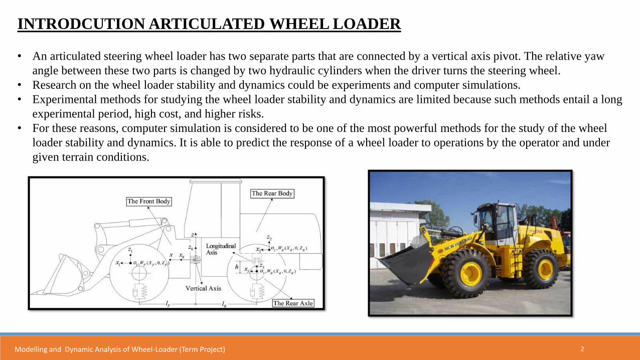
• An articulated steering wheel loader has two separate parts that are connected by a vertical axis pivot. The relative yaw
angle between these two parts is changed by two hydraulic cylinders when the driver turns the steering wheel.
• Research on the wheel loader stability and dynamics could be experiments and computer simulations.
• Experimental methods for studying the wheel loader stability and dynamics are limited because such methods entail a long
experimental period, high cost, and higher risks.
• For these reasons, computer simulation is considered to be one of the most powerful methods for the study of the wheel
loader stability and dynamics. It is able to predict the response of a wheel loader to operations by the operator and under
given terrain conditions.
Modelling and Dynamic Analysis of Wheel-Loader (Term Project)
3
With respect to the global coordinate system (o−xyz), six motions exist in the local coordinate
system (o0−x0y0z0) as listed below:
• Forward displacement (x),
• lateral displacement (y)
• Vertical displacement (z)
• roll (θ)
• pitch (ψ)
• yaw (φ),
Modelling and Dynamic Analysis of Wheel-Loader (Term Project)
4
MATHEMATICAL MODELLING AND GOVERNING EQUATIONS
Modelling and Dynamic Analysis of Wheel-Loader (Term Project)
5
Governing equations: Lagrange equations were used to derive the governing equations of motion for the wheel loader system
The kinetic energy of the system can be written as
The potential energy of the system can be written as
Modelling and Dynamic Analysis of Wheel-Loader (Term Project)
6
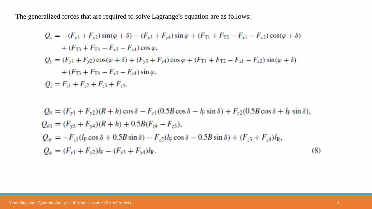
The generalized forces that are required to solve Lagrange’s equation are as follows:
Modelling and Dynamic Analysis of Wheel-Loader (Term Project)
7
Given that the loader’s longitudinal speed is constant, the traction forces FTi, rolling resistance forces Fxi, and
component force of gravity along the longitudinal direction are balanced.
Therefore, the longitudinal forces are:
Modelling and Dynamic Analysis of Wheel-Loader (Term Project)
8
MATHEMATICAL MODELLING FLOWCHART
Modelling and Dynamic Analysis of Wheel-Loader (Term Project)
9Modelling and Dynamic Analysis of Wheel-Loader (Term Project)
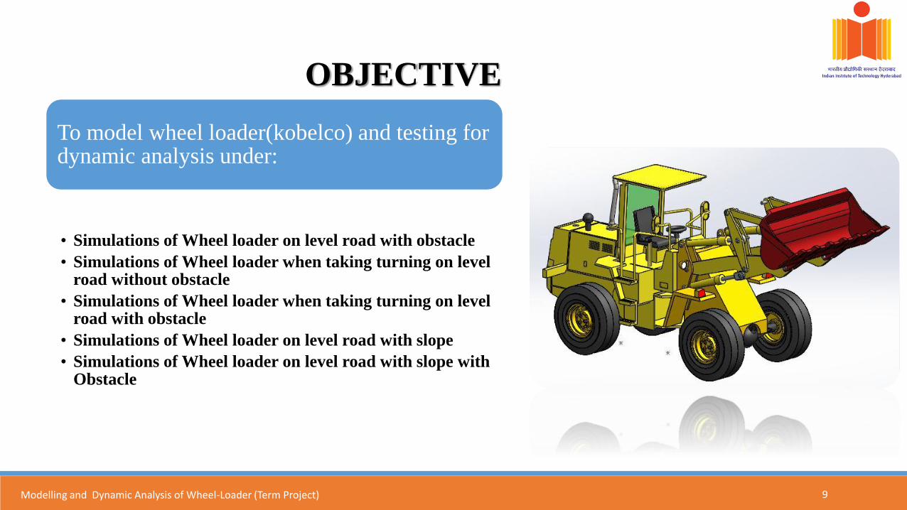
OBJECTIVE
To model wheel loader(kobelco) and testing for dynamic analysis under:
• Simulations of Wheel loader on level road with obstacle
• Simulations of Wheel loader when taking turning on level road without obstacle
• Simulations of Wheel loader when taking turning on level road with obstacle
• Simulations of Wheel loader on level road with slope
• Simulations of Wheel loader on level road with slope with Obstacle
10
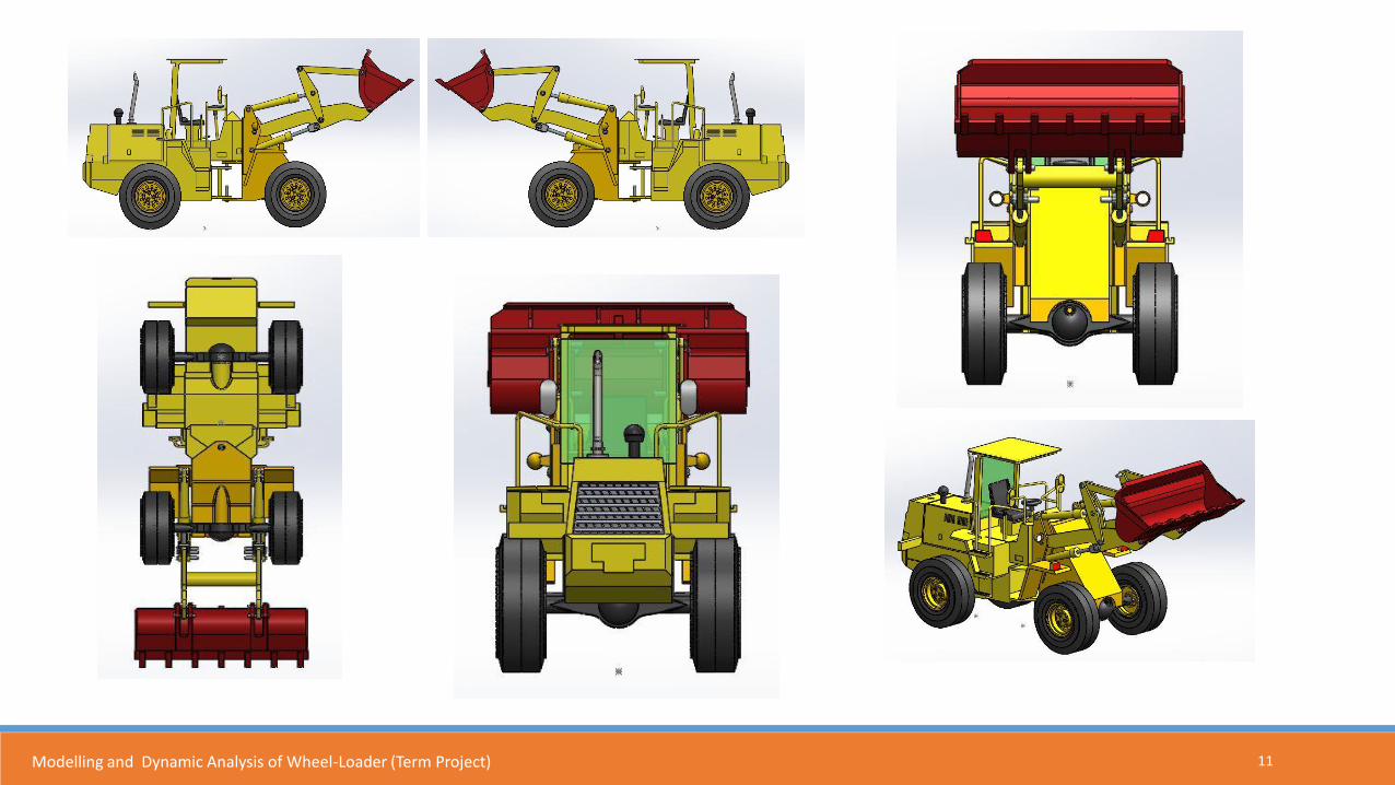
CAD MODEL:
Modelling and Dynamic Analysis of Wheel-Loader (Term Project)
11Modelling and Dynamic Analysis of Wheel-Loader (Term Project)
12Modelling and Dynamic Analysis of Wheel-Loader (Term Project)
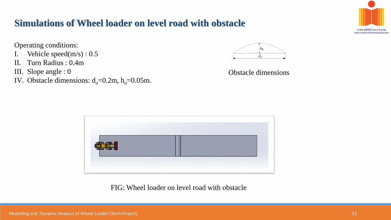
Simulations of Wheel loader on level road with obstacle
Operating conditions:
I. Vehicle speed(m/s) : 0.5
II. Turn Radius : 0.4m
III. Slope angle : 0
IV. Obstacle dimensions: do=0.2m, ho=0.05m.Obstacle dimensions
FIG: Wheel loader on level road with obstacle
13Modelling and Dynamic Analysis of Wheel-Loader (Term Project)
Results of simulation of Wheel loader on level road with obstacle.
Velocity Vs Time
Acceleration vs time
Pitching angle Vs Time
14Modelling and Dynamic Analysis of Wheel-Loader (Term Project)
Simulations of Wheel loader when taking turning on level road without obstacle.
Operating conditions:
Vehicle speed(m/s) : 0.5
Turn Radius : 0.4m
Slope angle : 0
15Modelling and Dynamic Analysis of Wheel-Loader (Term Project)
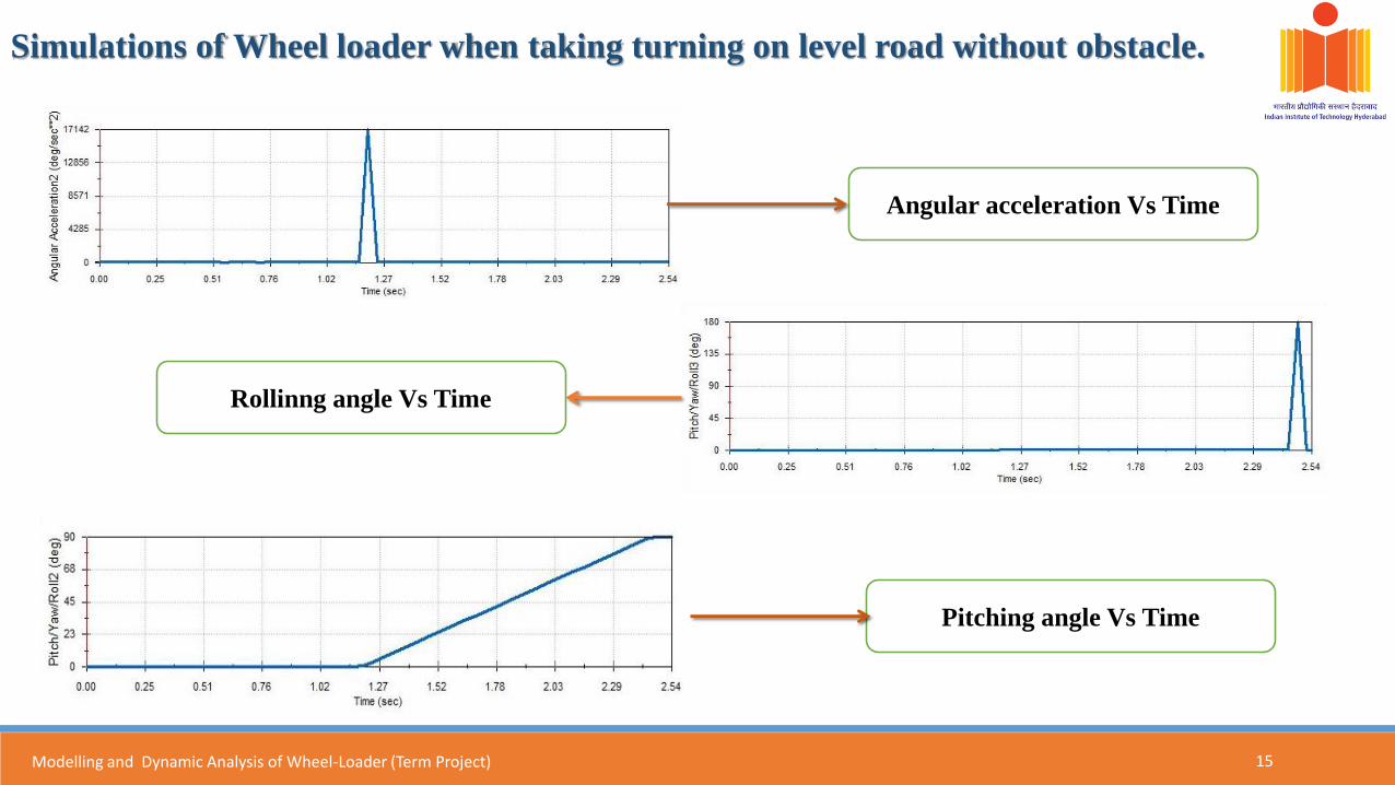
Simulations of Wheel loader when taking turning on level road without obstacle.
Angular acceleration Vs Time
Pitching angle Vs Time
Rollinng angle Vs Time
16Modelling and Dynamic Analysis of Wheel-Loader (Term Project)
Simulations of Wheel loader when taking turning on level road with obstacle.
Operating conditions:
Vehicle speed(m/s) : 0.5
Turn Radius : 0.4m
Slope angle : 0
Obstacle dimensions: do=0.2m, ho=0.05m.
Angular velocity Vs Time
17
Angular acceleration Vs Time
Rollinng angle Vs Time
Pitching angle Vs Time
Result of simulations of Wheel loader when taking turning on level road with obstacle.
Modelling and Dynamic Analysis of Wheel-Loader (Term Project)
18Modelling and Dynamic Analysis of Wheel-Loader (Term Project)
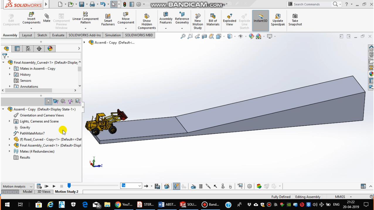
Simulations of Wheel loader on level road with slope.
Operating conditions:Vehicle speed(m/s) : 0.3Slope angle(Degree) : 16.69 Height of Slope : 300mmLength of Slope : 1000mm
Linear Acceleration v/s Time PlotLinear Velocity v/s Time Plot
Rolling Angle v/s Time Plot
19Modelling and Dynamic Analysis of Wheel-Loader (Term Project)
Simulations of Wheel loader on level road with slope with Obstacle.
Operating conditions:
Vehicle speed(m/s) : 0.3
Slope angle(Degree) : 16.69
Height of Slope : 300mm
Length of Slope : 1000mm
Obstacle dimensions: do=0.2m, ho=0.05m.
Linear Velocity v/s Time PlotLinear Acceleration v/s Time Plot
20
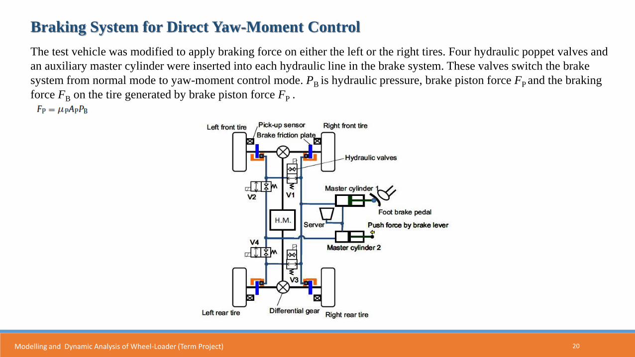
Braking System for Direct Yaw-Moment Control
The test vehicle was modified to apply braking force on either the left or the right tires. Four hydraulic poppet valves and
an auxiliary master cylinder were inserted into each hydraulic line in the brake system. These valves switch the brake
system from normal mode to yaw-moment control mode. PB is hydraulic pressure, brake piston force FP and the braking
force FB on the tire generated by brake piston force FP .
Modelling and Dynamic Analysis of Wheel-Loader (Term Project)
21
Braking System for Direct Yaw-Moment Control
Where AP is the cross-sectional area of the front or rear brake piston, and µP
is the friction coefficient of the brake friction plate. And rtire is the radius of
the tire. The factor of 2 indicates that FP acts both sides of the friction plate.
Modelling and Dynamic Analysis of Wheel-Loader (Term Project)
22
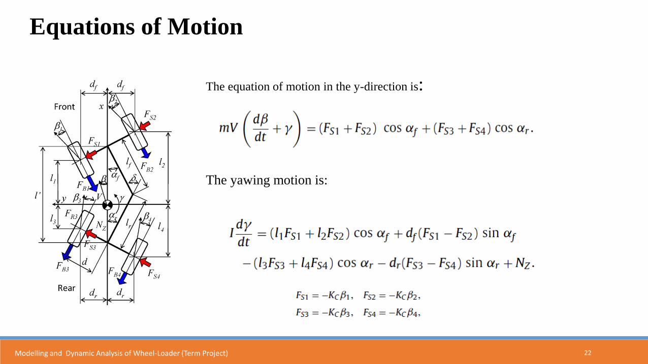
Equations of Motion
The equation of motion in the y-direction is:
The yawing motion is:
Modelling and Dynamic Analysis of Wheel-Loader (Term Project)
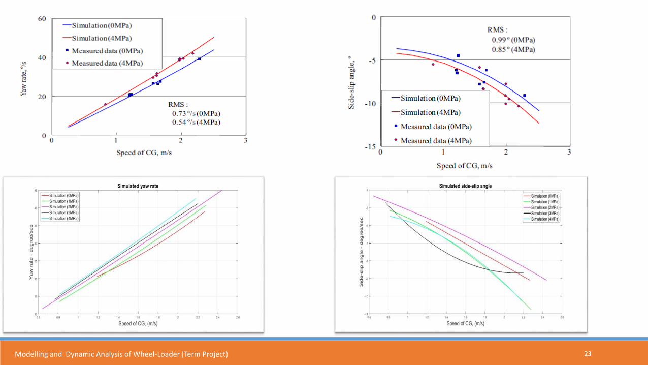
2323Modelling and Dynamic Analysis of Wheel-Loader (Term Project)
24Modelling and Dynamic Analysis of Wheel-Loader (Term Project)
25
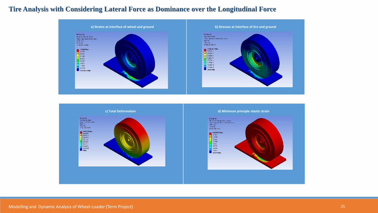
Tire Analysis with Considering Lateral Force as Dominance over the Longitudinal Force
a) Strains at interface of wheel and ground b) Stresses at interface of tire and ground
c) Total Deformation d) Minimum principle elastic strain
Modelling and Dynamic Analysis of Wheel-Loader (Term Project)
26
27Modelling and Dynamic Analysis of Wheel-Loader (Term Project)
28
Recent Advancements in wheel loader
Electric Compact Wheel Loader:
• The electric compact wheel loader delivers zero emissions, significantly lower noise levels, improved efficiency and
reduced operational costs, compared to its conventional counterparts.
• Combustion engine is replaced with a lithium ion battery. This stores enough electric energy to operate the machine
for eight hours in its most common applications, such as light infrastructure construction and landscaping. The wheel
Loader also incorporates two dedicated electric motors, one for the drivetrain and one for the hydraulics. Decoupling
the subsystems gives higher efficiency in both the systems and the entire machine.
Hybrid Powertrain:
• In this innovation, the power is delivered from the Engine to the wheels and other components through two paths, a
hydrostatic and mechanical path. The power delivery paths can be alternated depending upon the type of requirement,
either high speed-low torque or low speed-high torque applications.
Hybrid PowertrainElectric Wheel Loader
Modelling and Dynamic Analysis of Wheel-Loader (Term Project)
29
References
• Dynamic model and validation of an articulated steering wheel loader on slopes and over obstacles (http://dx.doi.org/10.1080/00423114.2013.800893)
• Iida M, Nakashima H, Tomiyama H. Small-radius turning performance of an articulated vehicle by direct yaw moment control. Comput Electron Agric. 2011;76:277–283.