Modeling and Simulation of Carbon dioxide Adsorption on Silica Aerogel Storage System Minju N & S. S. Savithri Materials Science and Technology Division CSIR-National Institute for Interdisciplinary Science and Technology (NIIST) Trivandrum, Kerala, India.
Transcript
Modeling and Simulation of Carbon dioxide Adsorption on Silica Aerogel Storage System
Minju N & S. S. Savithri
Materials Science and Technology DivisionCSIR-National Institute for Interdisciplinary Science and
Technology (NIIST)Trivandrum, Kerala, India.
Objectives
➢ Development of a predictive model for betterunderstanding of new adsorbent for CO2 duringadsorbent-desorption cycle including all transportphenomena.
➢ Validation of the model with literature results for H2storage
➢ Prediction of pressure, temperature distribution atvarious locations in the storage tank
Ref: http://www.climate-change-knowledge.org
CO2 Capture and Sequestration (CCS)
▪ Safe strategy for permanent storage are porous materials whichensures safer transportation from industries to long distancestorage sites without leakage.
▪ The storage of CO2 in porous materials Safe and easyaccess to CO2 for different applications
Surface engineered silica mesospheres – A promising adsorbent for CO2 Capture,(N. Minju, Balagopal N. Nair, A. Peer Mohamed , S. Ananthakumar) Separation andPurification Technology, 181 (2017), 192-200.
Functionalized Silica aerogel as solid adsorbent for CO2
Precursor solution
SiO2 Aerogel
Mechanical MixingRT
Sol gel Granulation
Aging at 250C
Solvent Exchange
Ambient drying, 55oC
Washing for 12h with distilled water
2 mm
5
✓ Low-cost water-glass as silica source✓ Ambient pressure drying
Problem formulation
Simulation of heat and mass transfer process for CO2 storage duringadsorption-desorption cycle in a fixed column filled with modifiedsilica aerogels.
▪ More realistic storage tank is used as computational domain▪ Darcy’s law for charging of CO2 in the storage tank▪ Considering the heat transfer between the bed and the walls of the container and
convective heat transfer between the outer wall and surroundings of the storage tank
▪ The adsorption isotherm in the adsorbent - The Dubinin-Astakov (D-A) microporevolume filling adsorption model
▪ Variational isosteric heat of adsorption based on DA model
𝑛𝑎 = 𝑛𝑚𝑎𝑥ex p −𝑅𝑇
𝜀
𝑚
𝑙𝑛𝑃𝑜𝑃
𝑚ε = α + βT
𝑞𝑠𝑡 = 𝛼 𝑙𝑛 Τ𝑛𝑚𝑎𝑥 𝑛𝑎
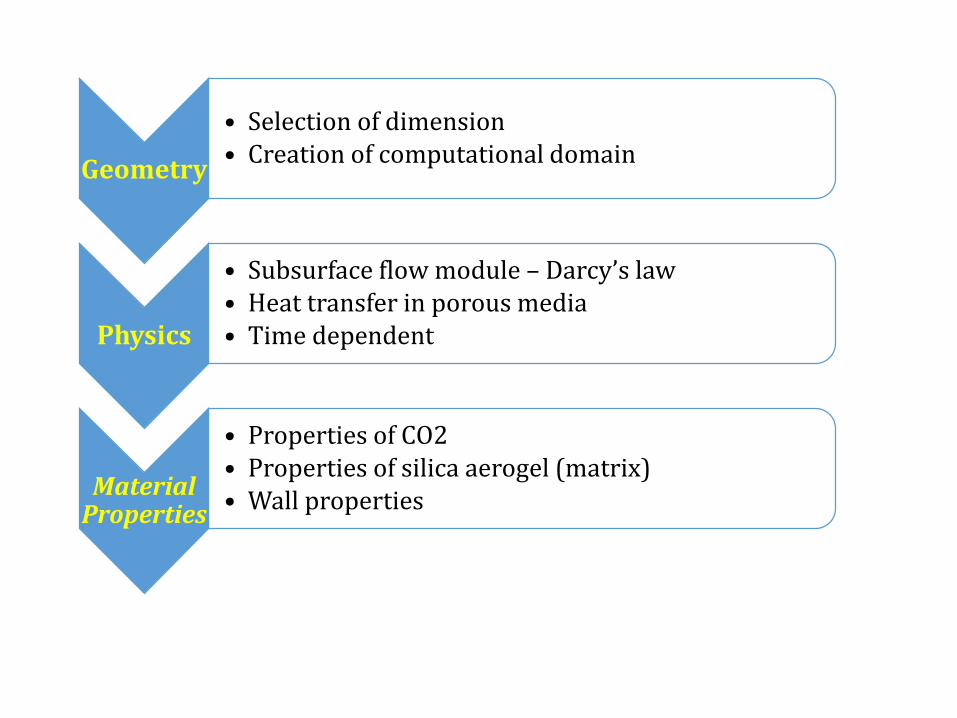
Geometry
• Selection of dimension• Creation of computational domain
Physics
• Subsurface flow module – Darcy’s law• Heat transfer in porous media• Time dependent
Material Properties
• Properties of CO2• Properties of silica aerogel (matrix)• Wall properties
Initial
• Inlet – mass source• Initial conditions for temperature, pressure etc• Heat flux, heat source term etc
During the carbon dioxide adsorption process, the heat of the system is transferred byconduction and convection in porous media. The partial differential equationrepresenting energy balance can be written as
(𝜀𝑏𝜌𝐶𝑂2 + 𝜌𝐶𝑂2𝑛𝑎𝑀𝐶𝑂2𝐶𝑝𝑔 + 𝜌𝑠𝑖𝑙𝑖𝑐𝑎𝐶𝑝𝑠)𝜕𝑇
𝜕𝑡+ 𝜌𝐶𝑂2𝐶𝑝𝑔 Ԧ𝑣. 𝛻𝑇 = 𝛻. 𝑘𝑒𝑓𝑓𝛻𝑇 + 𝑄 + Φ
𝑘𝑒𝑓𝑓 = 𝜀𝑏𝑘𝐶𝑂2 + 1 − 𝜀𝑏 𝑘𝑠𝑖𝑙𝑖𝑐𝑎
𝑄 = 𝑄𝑎 + 𝑄𝑝 = 1 − 𝜀𝑏 𝜌𝑠𝑖𝑙𝑖𝑐𝑎𝜕𝑛𝑎𝜕𝑡
𝑞𝑠𝑡 + 𝛾𝑇 𝜀𝑏𝜕𝑝
𝜕𝑡+ ҧ𝑣. 𝛻 𝑝
Cpg - specific heat capacity of CO2 (J kg-1 K-1)
Ԧ𝑣 - Darcy velocity (m s-1)
keff - effective thermal conductivity (W m-1 K-1)
Q - energy source term which combines the adsorption (Qa) and compression (Qp) heat source terms
(W m-3)
γ - volumetric thermal expansion coefficient which equals (1/T) for ideal gas (K-1)