This paper presents the modeling and simulation of offshore wind power platform for oil and gas companies. Wind energy hasbecome the fastest growing renewable energy in the world and major gains in terms of energy generation are achievable whenturbines are moved offshore. The objective of this project is to propose new design of an offshore wind power platform. Offshorewind turbine (OWT) is composed of three main structures comprising the rotor/blades, the tower nacelle, and the supportingstructure. The modeling analysis was focused on the nacelle and supporting structure. The completed final design was analyzedusing finite element modeling tool ANSYS to obtain the structure’s response towards loading conditions and to ensure it complieswith guidelines laid out by classification authority Det Norske Veritas. As a result, a newmodel of the offshore wind power platformfor 5MW Baseline NREL turbine was proposed.
1. Introduction
Demand of renewable energy plays an increasingly importantrole as fossil fuels become more and more expensive andharder to justify in expenses. It is expected that wind energywill contribute 1.1 trillion kilowatt-hours of the total 3.3trillion kilowatt-hours of renewable energy predicted to besupplied by 2030. Furthermore, it is expected that only sunand wind can provide economical alternative energy sources,as other exotic renewable energy sources remain expensiveand unproven [1, 2]. It is apparent that wind and sun aregoing to be the focus of future engineering efforts. Solarenergy is expected to become dominant as Arab countrieswith vast swaths deserts have already started investigating theprospect of generating solar power to continue developingtheir countries.
For wind energy, the future lies in developing offshorewind turbines that are capable of harnessing the much higherwind speeds available offshore while avoiding the problemof skyline pollution. A more detailed investigation of thecurrent and future wind energy outlook will be presentedin the next section. Wind turbines have progressed vastlysince the Dutch first used it to grind their mills and have
grown in power, from 25 kW to 2500 kW and more. Withthe growth of wind turbine size, the tools and engineeringexpertise used to overcome the challenges of harnessing windpower have also grown and expanded, with computer-aidedtools becoming more and more prolific and colleges anduniversities starting to offer courses on wind technology[3]. Modern offshore wind turbines are now required togenerate high-quality, network frequency electricity in anindependent and automatic manner and do so for 20 yearsor more continuously with low to no maintenance in someof the harshest environments in our planet. That will be thechallenges facing engineers today.
Initially, wind turbines which rotate on the vertical axiswere considered as a design as the expected advantages areomnidirectionality and having gears and power generatingequipment located at the base of the tower to lower loads.The shape of the turbine is like an onion, also called the“troposkein curve.” The design failed due to the inherentinefficiencies of the rotor and extra weight in constructionas well as serious metal-fatigue problems due to the tension-loaded rotors [3]. However, the design is still viable in low-power applications and can be mounted on the rooftops ofbuildings.
Hindawi Publishing Corporatione Scientific World JournalVolume 2015, Article ID 819384, 11 pageshttp://dx.doi.org/10.1155/2015/819384
2 The Scientific World Journal
The one bladed design is structurally the most efficient asall the blade area is concentrated on one blade. However, thedesign needs to spin at a higher speed (relative tomultibladeddesigns) to generate power and this leads to higher blade andtower loads. This high speed often generates a lot of noisewhich can be undesirable in onshore designs. The use of acounterbalance to give the structure static balance is alsoinefficient use of weight. Hence, commercially, one bladeddesign has been mostly eliminated.
According to Gardner et al. in Wind Energy–The Facts[3], wind turbines utilize stall and pitch regulation in orderto limit the rotor power when experiencing high operationalwind speeds. Stall regulation is where the speed of therotor is held constant or approximately constant even underincreasing wind speeds. This causes the angle of flow overthe blade sections to steepen. In effect, the blades becomeincreasingly stalled and thus limit the power to acceptablelevels, without requiring any additional active control. Aero-dynamicists were initially shocked at the idea of using stall asa form of limiting power because in flight aerodynamics, stallis often fatal and can cause planes and helicopters to crash.However, it proved to be effective to control overspeedingand the solution is unique to the wind energy industry. Thehistory of offshore wind power generation is fairly recent: theworld’s first offshore wind park was built in 1986 off the coastof Denmark. Sixteen 55 kW units produced electricity forthe 4,000 citizens in nearby Ebeltoft. Following the project’ssuccess, similar parks were built off Scandinavian coaststhrough the late 1990s. Danish and German firms are knownfor their expertise when it comes to offshore wind, andthey will likely benefit from the current boom that offshorewind power is experiencing. Companies and governments areplanning to build 25 offshore wind parks in five Europeancountries with a total capacity of some 1,100MW.
There are still some hurdles offshore wind energy hasto overcome, mainly the high costs connected to construc-tion, maintenance, and operation. Offshore wind units areconstantly exposed to high winds, salt water, and corrosivesea air, which makes them more vulnerable to damage thanland units. There are many engineering challenges faced byoffshore wind turbine technology. The harsh environmentrepresents some of the more extreme environments on ourplanet, and with natural phenomenon such as typhoons andrough seas, building a floating structure that requires nomaintenance over the course of decades will require greatengineering feat [6].
The offshore wind market today is heavily influenced bytechnologies developed from offshore oil and gas. The foun-dation design has become the biggest factor that will affectthe performance of offshore wind turbine platform.However,some designs from offshore oil and gas are fundamentallyincompatible with offshore wind, such as the use of dynamicpositioning. This paper will carry out the platform design ofoffshore wind turbine and propose a new foundation designfrom the commonly used Pile foundation being used today.The objective of this project is to create the foundation andperform the finite element analysis on the platform design for5MW Baseline NREL turbine.
2. Literature Review
The foundation or support structure forms the bulk ofthe OWT installation costs and this is even more so indeep waters. Subroto et al. [11] reported that, for shallowwaters somewhere between 20 to 25 meters, monopile andgravity based support structure are dominant and very cost-effective. For transitional waters, the depths are up to 50meters. Beyond that, the waters are considered deep water forwhich commercial wind farms have not yet been developed,although prototypes and proof-of-concept designs have beentested out. Figure 1 shows an overview of the different typesof support structure proceeding from shallow to deep waters.Gravity based design is also commonly used consisting of aheavy base connected to the support structure and turbineas shown in Figure 2. However, it is expensive and usedonly in very shallow waters. The tripod is another preferreddesign, and many different configurations have been testedwith varying geometries and also with and without drivenpiles for each leg.
Figure 3 shows another design which is jacket based. Itutilizes a series of tubular joints to form a square taperedstructure.This structure is used widely in the offshore oil andgas production. For adoption for OWT use, the jacket designhas been studied due to very favorable, as the additional windloading does not significantly detract from the jacket’s torsionstrength.
It has been demonstrated in China [5] and Germany [12],where the environmental loads are quite extremewith ice andearthquake in the case of China and very deep waters of 50mand large 5MW turbines in the case of Germany.The suctioncaisson foundation is the leading candidate for Hong Kong’sown offshore wind turbine farm [6] as it is environmentallyfriendly and installation does not disturb the surroundingmarine life as shown in Figure 4. It is simply lowered into thesite together with a powerful pump. Once settled, the pumpwill extract water, creating a pressure difference which forcesthe caisson into the seabed. Once completed, the caissonforms a powerful seal at the seabed due to the pressuredifference, and the pump is undocked.
Caissons can be combined with guy wires and monopoleinto a guyed pile caisson [13] design although it has notbeen explored yet for use with OWT. Figure 5 shows thethree structures shown above are three main concepts toprovide stability in transitional water depths.They are shownstabilized using catenary or tension lines and permit someamount of movement; thus, these structures are also knownas compliant towers. However, not all of the concepts requirestabilizing lines.
Butterfield [14] elaborates on the three concepts. The firstis ballast stabilized, where large tanks called ballast are hungbelow a turbine to provide a rightingmoment with high iner-tial resistance to pitch and roll. Mooring lines help stabilizethe structure. The second is also known as a Tension LegPlatform, where tension in the mooring lines helps providethe rightingmoment. Finally, the buoyancy stabilized conceptachieves stability through use of distributed buoyancy; thisprinciple is demonstrated in barges. Again as mentionedearlier, the use of tension lines for stability is optional and
The Scientific World Journal 3
Monopile
Scour protection
TransitionExternal J tubes
Grouted
Work platform
platformIntermediate
Tower
Boat landing
Substructure
Foundation
Figure 1: Monopole foundation, consisting of a driven pile [3].
Tripod based foundation
Gravity based foundation
Figure 2: Gravity based and tripod foundation concepts [4].
depends on the size of the structure and environmental loads.All commercial concepts being explored for stability arehybrids of these threemain designs, exploiting the advantagesof all three methods to gain static stability.
Figure 6(a) shows an example: Dutch Tri-Floater hasdistributed buoyancy tanks attached to the central towerthrough truss arms. This achieves stability primarily throughweighted water plane area (buoyancy) but weight of the steeltanks and truss structure will also provide significant mass toresist overturning moments (ballast). The catenary mooringsprovide some additional resistance to overturning, mainlydue to the mass of the lengthy chain that extends out to aconservative suction pile mooring (mooring line stabilized).As another example, as shown in Figure 6(b), conceived byMarine Innovation & Technology and owned by PrinciplePower, the WindFloat is a semisubmersible, three-columnstructure, with a turbine tower, truss, and “water entrapmentheave plates” at each column’s base, designed to reduce pitch
Jacket structure
Figure 3: Jacket structure [5].
and yaw and make the entire structure more compact. Itaims to support deployment of large capacity wind turbines(3.6MW to 10MW) in deep water (50 meters or greater).Table 1 shows the comparison of common foundations usedfor offshore wind power platform [9].
3. Methodology
During the first phase of the project, the main focus is onunderstanding the field of offshorewind turbine and to gathertechnical information regarding common installations. Thestate of computer-aided engineering use in this sector isalso gathered. Three key “modules” have been identifiedin the design and analysis of offshore wind turbines andthey are the rotor and blades, the nacelle, and finally thesupporting structure. Certification is also important as itrepresents an industry standard and the design should striveto meet the requirements set by certification authorities.As mentioned earlier, the primary document for referenceto this will be DNV’s standard. In considering the design,the blade and rotor are a tough subject due to the inher-ent modeling difficulties encountered even by commercialturbine manufacturers. As for the nacelle, the design willconsider the equipment installed, mechanical arrangement,and accessibility. A strategy for reliability andmaintainabilityis also developed.
Finally, the support structure design will follow wherenecessary the specifications lay out by NREL’s 5MW modeloffshore turbine. Phase two was focused on develop-ment/design of these three components and integration into aCADmodel, followed by computer-aided engineering (CAE)analysis on the model loaded by wave to see its response.
4 The Scientific World Journal
Non
plug
loadenvironmental
penetrationto assist
drawdownExtra
watertrapped
volume ofSmall
Marine clay
End bearing
Skinfriction
Skinfriction
Skinfriction
possibly proof loadpenetration andSuction to assistStage 3
Marine sand
Weathered rock
self-weightpenetration byInitialStage 2
touchdownBeforeStage 1
drawdownNatural
compressible
Stage 4In-placeresistance tovertical loads
Gravity +
Figure 4: Suction caisson foundation installation stages [6].
Ballast stabilized Mooring line stabilized Buoyancy stabilized
Figure 5: Several structures proposed for transition water depths [4].
Postprocessing was used to analyze the data and to visualizethe results. The next step is to input the load cases followingcertification authorities’ standard. Then, the solver is run toget the solutions for the problem posed. This is then fedthrough a postprocessor for a visual representation of results.
TheNREL offshore 5MWbaseline wind turbine has beenused to establish the reference specifications for a numberof research projects supported by the U.S. Department ofEnergy’s Wind Energy Technologies Program. In addition,the integrated European Union UpWind research programand the International Energy Agency Wind Annex XXIII
Offshore Code Comparison Collaborative have adopted theNREL offshore 5MWbaseline wind turbine as their referencemodel. The model has been, and will continue to be, usedas a reference by research teams throughout the world tostandardize baseline offshore wind turbine specifications andto quantify the benefits of advanced land- and sea-basedwindenergy technologies [15].
The 5MW rating is large by today’s standards but isassumed to be the minimum rating necessary to make afloating wind turbine system economical because of the largeproportion of the costs in the support platform. The wind
The Scientific World Journal 5
(a)
Turbine lighting
Gangway
Tri-column triangular
Mooring system and anchorsHeavy plates and stiffeners
Table 1: Comparison of common foundations (Source: [9]).
Type Environmental impact Technical benefits Limitations
MonopileInstallation consists of hammeringinto seabed that can causedisturbance to local marine life.
Simple and proven design.
(i) Limited to water depths of about 10 meters.Deeper waters limit technical feasibility ofmanufacturing large diameter piles.(ii) Requires scour protection for very shallowwaters.(iii) Unsuitable for locations with large boulders.
Suction caisson Very little impact. Can be used in areas of highgeological soft mud.
Use depends on site conditions. Boulders onseabed limit use.
Gravity-type Significant disturbance of seabed. Simple and proven design. Requires a hard seabed as well as seabedpreparation.
Tripod No significant impact. (i) Simple and proven design.(ii) Minimal site preparation.
No major limitations besides being limited towater depths of about 30m.
Compliant tower No significant impact.Suitable for deep waters;compliance reduces need forstiff structure.
Requires very accurate positioning of tendons onseabed.
Jacket Impact on seabed duringinstallation of jacket legs.
Suitable for deepertransitional waters. Limited to water depths from 20 to 50m.
turbine design is typical of utility-scale, land- and sea-based,and multimegawatt turbines. Based upon many theoreticalstudies, the gross properties of the theoretical turbine wereestablished as in Table 2 [10].
Furthermore, the design of the supporting structuremustbe located in deeper waters where monopole designs areunfeasible. Figure 7 shows the dimension for the suctionscaisson. The detail dimension for the top suctions cais-son is 8m × ⌀1m and for the bottom suctions caisson is1m × ⌀5m.
The detail design will be guided by reference to OS-J101standard. First, the material has been identified as specialdue to the significance of the component in terms of failureconsequence and the fact that application of stress conditionmay increase the probability of brittle fracture. This meansthe material ultimately selected must come with a TestCertificate EN10204 3.2 with a Category I inspection categoryfor weld inspections. According to Section 10 A101 [10], therequirements for foundation design are applicable only topile, gravity-type, and stability of sea bottom foundations.
6 The Scientific World Journal
8
1.25
∅5
∅1
Figure 7: Dimensions for the suction caisson (meters).
Table 2: Gross properties chosen for theNREL 5MWBaselinewindturbine [10].
Rotor and hub diameter 126m, 3mHub height 90mCut-in, rated, and cut-out windspeed 3m/s, 11.4m/s, and 25m/s
Cut-in, rated rotor speed 6.9 rpm, 12.1 rpmRated tip speed 80m/sOverhang, shaft tilt, and precone 5m, 5∘, 2.5∘
Rotor mass 110,000 kgNacelle mass 240,000 kgTower mass 347,460 kgCoordinate location of overallCM (−0.2m, 0.0m, and 64.0m)
Other types not specifically covered will be specially consid-ered. Nonetheless, the specifications will be followed wherepossible.
For an effective stress stability test, analysis should becarried out on strength parameters of the soil based onlaboratory shear strength analysis with pore conditionsincluded. However, this was unable to be performed in orderto validate the specific soil characteristics of a site. Hence,values are taken from literature. In this project, the corrosionprotection was not included in the simulation. Generally,
Table 3: Material specifications for Steel 355D.
Property Value UnitsElastic modulus 210𝑒 + 009 N/m2
installing cathodic and coating are the recommended protec-tionmethod for the outer skin of the structure while enclosedspaces can use biocides. A corrosion allowance is also usuallyset and depends on the chloride content of the site seawater.
Thematerial properties corresponding to commonly usedoffshore steel (API-2H, 355D, etc.) are entered in ANSYSsoftware. Table 3 lists the details of material specifications forsteel 355D.
Much of the information for offshore wind energy devel-opment is referenced to a proceeding paperwritten byChianget al. [1], titled “The Potential of Wave and Offshore WindEnergy in Around the Coastline of Malaysia that Face theSouth China Sea,” presented at the International Symposiumon Renewable Energy held in Kuala Lumpur, Malaysia. Inthis project, the region of Sabah, Sarawak, and East Coastof Peninsular Malaysia were identified as potential sites foroffshore wind platforms with the water depth up to 50m.Theannual wind speeds averaged at about 1-2 knots, reaching amaximum of 5 knots during monsoon periods.
The surface model contains the shown dimensions andwill be imported into ANSYS AQWA Workbench later.However, surface model does not have mass informationwhich ANSYS can automatically generate.The samemodel isrecreated as a solidmodel and shelled to 10mm.The resultingsolid model is a real-world representation of the structureand is created so that mass and moment properties can beextracted from SolidWorks.
Autogenerated mass information based on dimensionand material specification is as follows:
Mass properties of structure solidmodel (part config-uration: default).Output coordinate system: —default—.Density = 7850.00 kilograms per cubic meter.Mass = 10444.91 kilograms.Volume = 1.33 cubic meters.Surface area = 266.49 m2 .Center of mass: (meters):
𝑋 = 4.10,
𝑌 = 2.25,
𝑍 = 3.33.
(1)
Principal axes of inertia and principal moments ofinertia: (kilograms ∗ square meters).
The Scientific World Journal 7
Restrict D.O.F.
Foundation model
Gravitational load
Wave pressureloading
Contact surface
Tower pressureloading
Soil model
Total elements:83963
Total nodes:136624
Figure 8: Summary of ANSYS model.
Taken at the center of mass:𝐼𝑥= (0.88, 0.48, 0.00) ,
𝑃𝑥= 189209.00,
𝐼𝑦= (−0.48, 0.88, 0.00) ,
𝑃𝑦= 200253.92,
𝐼𝑧= (0.00, 0.00, 1.00) ,
𝑃𝑧= 226763.10.
(2)
Moments of inertia: (kilograms ∗ square meters).Taken at the center of mass and aligned with theoutput coordinate system:
𝐿𝑥𝑥= 191764.93,
𝐿𝑥𝑦= 4658.03,
𝐿𝑥𝑧= 0.00,
𝐿𝑦𝑥= 4658.03,
𝐿𝑦𝑦= 197697.99,
𝐿𝑦𝑧= 0.00,
𝐿𝑧𝑥= 0.00,
𝐿𝑧𝑦= 0.00,
𝐿𝑧𝑧= 226763.10.
(3)
Moments of inertia: (kilograms ∗ square meters).Taken at the output coordinate system:
𝐿𝑥𝑥= 360278.82,
𝐿𝑥𝑦= 100960.08,
𝐿𝑥𝑧= 142481.33,
𝐿𝑦𝑥= 100960.08,
𝐿𝑦𝑦= 488874.48,
𝐿𝑦𝑧= 78181.54,
𝐿𝑧𝑥= 142481.33,
𝐿𝑧𝑦= 78181.54,
𝐿𝑧𝑧= 455110.32.
(4)
The density will be used in material specifications insideANSYS Classic. The Center of Mass and Moment of Inertiais also useful as an input parameter in the HydrodynamicDiffraction analysis for a more realistic approximation of theproblem. Figure 8 shows the summary of ANSYS model.
For the wave pressure loading, results from ANSYSHydrodynamic Diffraction, which is a contour plot of themaximum pressure experienced, is used by approximatingit inside the model with the highest pressure on the top,mediumpressure in between, and low pressure on the bottom
8 The Scientific World Journal
20156 max
20037
19917
19798
19679
19560
19440
19321
19202
19082 min
Figure 9: Pressure force due to wave loading.
of the model. It is assumed that this maximum pressure willcome from the same direction at once.
As for the tower loading, calculation for the pressure isas follows: NREL 5MW turbine total mass including tower,rotor, and nacelle (approx.): 700,000 kg. By assuming thetower diameter to be approximately 5m at the base, thepressure exerted on platform is 546548 Pa.The effect of windloading is assumed to be insignificant and not accounted forin the model.
4. Results and Discussion
Figure 9 shows the pressure force due to wave loading basedon ANSYS AQWA Hydrodynamic Diffraction result. Theresult shown in Figure 7 indicates a wave frequency of0.072Hz with amplitude of 1m and the pressure contour isshown in units of Pascal. As expected, the highest forces arefound near the top of the structure where waves have thestrongest impact. Lowering down the structure, most of theforce is contributed by hydrostatic forces that increase thedeeper we go. The caissons were not modeled as they areassumed to be close to the bottom of the sea and do notaccount for much wave/current loading.
The pressure reading is given as an averaged solutionfrom wave forces coming from all directions. Hydrostaticpressure is automatically incorporated into the solution,leading to a small difference between the pressure at thetop (mainly contributed by wave forces) and the pressureat the bottom (mainly contributed by hydrostatic pressure).The total displacement vector plot indicates that the area ofhighest displacement comes at the center with the maximumdisplacement being 0.236m, or about 25 cm (Figure 10). Thisis an acceptably small value given the fact that the structureis located out at sea with large wave forces acting on it. Thestructure shows little movement of the caisson, making it astable structure for use.Themaximum displacement is about0.8 cm occurring near the base on the structure.
The stress intensity plots show the maximum stressesoccurring at 0.198𝑒10 Pascal, which is only within 25% ofthe tensile strength of the material at 80𝑒9 Pascal, with goodroom for a large factor of safety (Figure 11). The plot did not
0
0.026271
0.052543
0.078814
0.105085
0.131357
0.157628
0.183899
0.210171
0.236442
Figure 10: Displacement Vector Sum (Nodal Solution).
0
0.220E+09
0.441E+09
0.661E+09
0.881E+09
0.110E+10
0.132E+10
0.154E+10
0.176E+10
0.198E+10
Figure 11: Stress intensity (Nodal Solution).
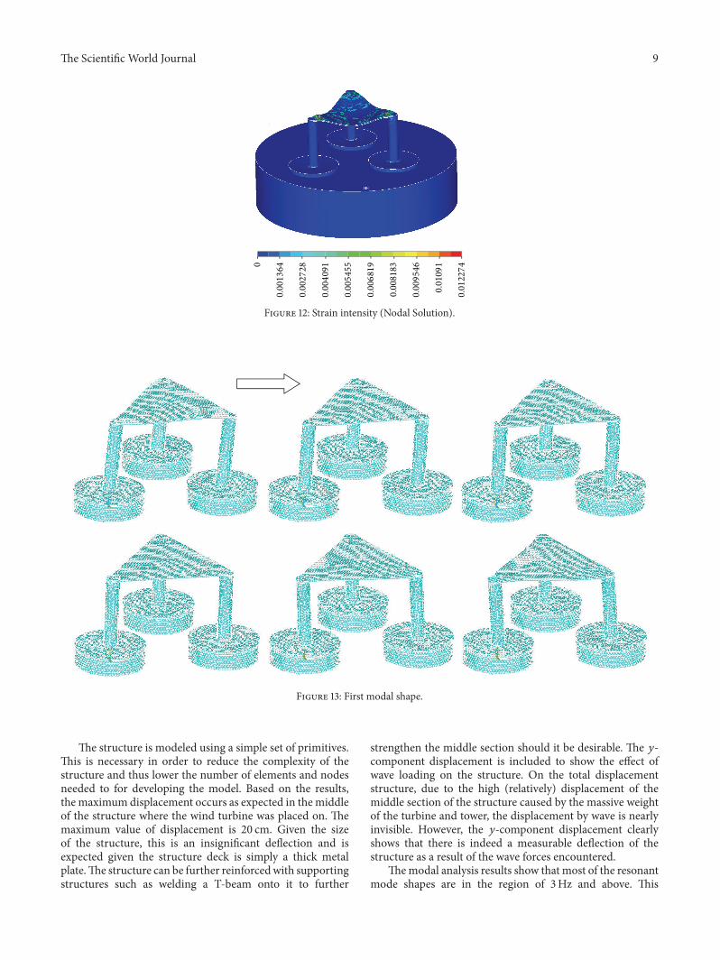
show a smooth curve due to the use of coarse elements. Asthe elements get finer, the transitions between forces will besmoother. The strain intensity plot is similar to the stressintensity, showing a maximum strain of 0.122 (Figure 12).The following are frame-by-frame animations of the firstthree lowest modal shapes successfully extracted by ANSYS.Structure displacement is exaggerated to aid visualization.
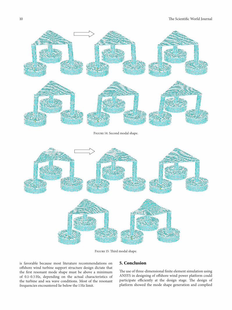
Figures 13, 14, and 15 show three generations of modeshapes were developed in order to represent the model.The following are frame-by-frame animations of the firstthree lowest modal shapes successfully extracted by ANSYS.Structure displacement is exaggerated to aid visualization.Table 4 lists themodal frequency.Thefirstmode shape occursat 4.6Hz, the second at 4.7Hz, and the third at 7.5Hz.
This informationwill be useful in analyzing the structure’scompliance with the dynamic conditions faced at the finalinstallation site. The first two modal shapes are important forcomparing against wave induced resonance while the third isimportant for resonance due to turbine and rotor/blades.
The Scientific World Journal 9
0
0.001364
0.002728
0.004091
0.005455
0.006819
0.008183
0.009546
0.01091
0.012274
Figure 12: Strain intensity (Nodal Solution).
Figure 13: First modal shape.
The structure is modeled using a simple set of primitives.This is necessary in order to reduce the complexity of thestructure and thus lower the number of elements and nodesneeded to for developing the model. Based on the results,the maximum displacement occurs as expected in themiddleof the structure where the wind turbine was placed on. Themaximum value of displacement is 20 cm. Given the sizeof the structure, this is an insignificant deflection and isexpected given the structure deck is simply a thick metalplate.The structure can be further reinforcedwith supportingstructures such as welding a T-beam onto it to further
strengthen the middle section should it be desirable. The 𝑦-component displacement is included to show the effect ofwave loading on the structure. On the total displacementstructure, due to the high (relatively) displacement of themiddle section of the structure caused by the massive weightof the turbine and tower, the displacement by wave is nearlyinvisible. However, the 𝑦-component displacement clearlyshows that there is indeed a measurable deflection of thestructure as a result of the wave forces encountered.
Themodal analysis results show that most of the resonantmode shapes are in the region of 3Hz and above. This
10 The Scientific World Journal
Figure 14: Second modal shape.
Figure 15: Third modal shape.
is favorable because most literature recommendations onoffshore wind turbine support structure design dictate thatthe first resonant mode shape must be above a minimumof 0.1–0.5Hz, depending on the actual characteristics ofthe turbine and sea wave conditions. Most of the resonantfrequencies encountered lie below the 1Hz limit.
5. Conclusion
The use of three-dimensional finite element simulation usingANSYS in designing of offshore wind power platform couldparticipate efficiently at the design stage. The design ofplatform showed the mode shape generation and complied
The Scientific World Journal 11
Table 4: The modal frequency.
Set Frequency Load step Substep1 4.6837 1 12 4.7102 1 23 7.5579 1 3
with the dynamic conditions faced at the final installationsite. The result analysis determined resonance which couldsignificantly reduce the lifespan of the structure. In theocean where there are a lot of dynamic interactions betweenwind, wave, and structure, it is important that the structure’sresonant frequencies lie sufficiently away from the meanresonant frequencies.
Conflict of Interests
The author declares that there is no conflict of interestsregarding the publication of this paper.
References
[1] E. P. Chiang, Z. A. Zainal, A. Narayana, and K. N. Seetaramu,“The potential of wave and offshore wind energy in aroundcoastline ofMalaysia that face the South China Sea,” in Proceed-ings of the International Symposium on Renewable Energy, KualaLumpur, Malaysia, September 2003.
[2] G. A. M. Van Kuik, “The lanchester-betz-joukowsky limit,”Wind Energy, vol. 10, no. 3, pp. 289–291, 2007.
[3] P. Gardner, A. Garrad, P. Jamieson, H. Snodin, and G. Nicholls,Wind Energy, The Facts, An Analysis of Wind Energy in theEU-25, vol. 1, European Wind Energy Association, Bruxelles,Belgium, 2002.
[4] North American Offshore Wind Project Information, “Off-shore Wind Turbine Foundations—Current & Future Pro-totypes,” 2015, http://offshorewind.net/Other Pages/Turbine-Foundations.html.
[5] Y. Wang, M. Duan, and J. Shang, “Application of an abandonedjacket for an offshore structure base of wind turbine in Bohaiheavy ice conditions,” in Proceedings of the 19th InternationalOffshore and Polar Engineering Conference, Osaka, Japan, June2009.
[6] Hong Kong Environment Protection Agency, Hong Kong Off-shore Wind Farm in Southeastern Waters, Hong Kong Environ-ment Protection Agency, 2009.
[7] M. J. Wolf and M. P. M. Van Der Meer, “Study to feasibility ofand boundary conditions for floating offshore wind turbines,”Tech. Rep. 011, Offshore Wind Energy, 2002.
[8] J. Shankleman, “Vestas floats plan forWindPlus offshore demo,”Business Green, 2011.
[9] European Wind Energy Association (EWEA), Wind Energy—The Facts: Volume 1 Technology, vol. 1, EWEA, Brussels, Bel-gium, 2004.
[10] J. Jonkman, “Definition of a 5-MW reference wind turbinefor offshore system development,” Tech. Rep. NREL/TP-500-38060, 2009.
[11] H. Subroto, J. Van Der Tempel, R. Narold, R. Van Gilst, H. J.Kooijman, and J. M. Peeringa, Offshore Wind Turbine BottomFounded Steel Support Structure for Offshore Wind Turbines in
Deeper Waters of the North Sea, Delft University Wind EnergyResearch Group, 2006.
[12] Wind Energy Agency Bremerhaven, “Jacket foundation foroffshore wind turbine under construction,” in Proceedings of theEuropean Offshore Wind Energy Conference, Berlin, Germany,December 2007.
[13] Oil and Gas Journal, “Tarpon Monotower Develops FurtherFrom 37 Field Applications,” 1999, http://www.offshore-mag.com/index/article-display/24940/s-articles/s-offshore/s-volume-59/s-issue-4/s-news/s-general-interest/s-tarpon-monotower-develops-further-from-37-field-applications.html.
[14] S. Butterfield, “Engineering challenges for floating offshorewind turbines,” in Proceedings of the Copenhagen OffshoreWindConference, Copenhagen, Denmark, 2007.
[15] J. M. Jonkman, “Dynamics modeling and loads analysis ofan offshore floating wind turbine,” Tech. Rep. NREL/TP-500-41958, 2007.