35
Innovation Intelligence ® Physical Component Modeling in Altair ScicosPro Application to Vibratory Pile Extraction Franck Delcroix European ATC - June 25 th 2014, Munich
| Date post: | 06-May-2015 |
| Category: |
Engineering |
| Upload: | altair-engineering |
| View: | 284 times |
| Download: | 3 times |

Innovation Intelligence®
Physical Component Modeling
in Altair ScicosPro
Application to Vibratory Pile Extraction
Franck Delcroix
European ATC - June 25th 2014, Munich
Copyright © 2014 Altair Engineering, Inc. Proprietary and Confidential. All rights reserved.
Presentation Outline
• Physical Component Modeling in ScicosPro
• The Coselica Library
• Application – Vibratory Pile Extraction
2

Copyright © 2014 Altair Engineering, Inc. Proprietary and Confidential. All rights reserved.
ScicosPro and Physical Component Modeling
ScicosPro is made for system level modeling approaches
(efficient handling of discrete time and events).
Modelica is adapted to component level modeling approaches.
But the basic formalisms are compatible, which allows for the use of
Modelica components in a ScicosPro model.
ScicosPro offers a Physical Component Modeling library based
on Modelica blocks (Coselica library)
3

Copyright © 2014 Altair Engineering, Inc. Proprietary and Confidential. All rights reserved.
ScicosPro – Hybrid System Modeling
Conventional ScicosPro blocks have clearly defined input and output
ports, where an input can be regarded as cause and an output as effect.
Models built solely with these blocks are causal models.
In contrast, most Modelica blocks have neither identifiable input nor
output ports. Instead, they have connector ports which propagate
physical quantities (e.g. electrical voltage and current), and it is a priori
undecided what quantity causes which effect.
4

Copyright © 2014 Altair Engineering, Inc. Proprietary and Confidential. All rights reserved.
Causal modeling (explicit blocks)
DuCxy
BuAxx
an explicit block
in ScicosPro
• Input and output ports are explicitly defined
• In the model there is an information flow
• The input/output behavior is expressed in C
• They are considered as black boxes by ScicosPro
5

Copyright © 2014 Altair Engineering, Inc. Proprietary and Confidential. All rights reserved.
To create a model with explicit blocks, you need
• to obtain all the equations
• to simplify the equations to obtain a differential equation (ODE/DAE)
C
CR
C
C
CRs
VOutput
RIVC
IV
VVV 0
RC
V
RC
VV CS
C
CV
Causal modeling (explicit blocks)
model equations differential equation
6

Copyright © 2014 Altair Engineering, Inc. Proprietary and Confidential. All rights reserved.
Constructing the model using explicit blocks based on the ODE can be
time consuming, error prone, and show no resemblance to the original
diagram.
CV
Causal modeling (explicit blocks)
7

Copyright © 2014 Altair Engineering, Inc. Proprietary and Confidential. All rights reserved.
• Have implicit ports (not a priory inputs or outputs)
• Each implicit block represents a physical component
dt
dVCI C
C
an implicit block
in ScicosPro
Acausal modeling (implicit blocks)
8

Copyright © 2014 Altair Engineering, Inc. Proprietary and Confidential. All rights reserved.
• Connected with special links (no flow direction)
• Modeling is just connecting the components
• The model looks like the physical system
• The behavior is expressed in the Modelica language
Acausal modeling (implicit blocks)
9

Copyright © 2014 Altair Engineering, Inc. Proprietary and Confidential. All rights reserved.
What is Modelica?
• Declarative instead of procedural
• Object oriented modeling language (inheritance, aggregation)
• Typed language
• Allows heterogeneous models (multi-domain models)
• Allows reuse of physical models
• Allows non-causal modeling (modeling using components)
• Equation based, i.e., using mathematical equations
• Hybrid modeling, i.e., event-based and continuous-time models
10

Copyright © 2014 Altair Engineering, Inc. Proprietary and Confidential. All rights reserved.
Modelica Applications
• Modelica is a non proprietary language and exists since 1996.
It is Standardized by Modelica Association.
• The Modelica models, being independent of the tool, can be
simulated on any Modelica simulator.
• Available tools include: MapleSim, Dymola, SimulationX,…
• Several free and commercial libraries are available.
11

Copyright © 2014 Altair Engineering, Inc. Proprietary and Confidential. All rights reserved.
Physical Component modeling blocks in ScicosPro
Coselica is library of ScicosPro blocks based on the Modelica Standard
Library.
It is essentially a library of physical components covering various physical
domains, such as mechanics, electrics/electronics, and thermodynamics.
These components are provided as ScicosPro blocks and they can be found in
one hierarchical palette named Coselica. All blocks have special connector ports
and connecting them is like assembling a physical network.
12

Copyright © 2014 Altair Engineering, Inc. Proprietary and Confidential. All rights reserved.
ScicosPro model, with Coselica blocks and standard blocks
How does it work in ScicosPro?
C
Block
13

Copyright © 2014 Altair Engineering, Inc. Proprietary and Confidential. All rights reserved.
Coselica Examples in ScicosPro
Hatch Mechanism – Mechanical/Electrical modeling Heat Transfer and Convection – Thermal modeling
CMOS – Electronic modeling
14

Innovation Intelligence®
Physical Component Modeling in ScicosPro
Application to Vibratory Pile Extraction
Study made by Dr. Dirk Reusch (Kybernetics)

Copyright © 2014 Altair Engineering, Inc. Proprietary and Confidential. All rights reserved.
Application Goals
A 23m long pile has been inserted 20m into the ground
and shall be extracted by means of a static force and a
dynamic (harmonic oscillating) force.
In order to achieve this, one has to overcome the shaft
resistance force of the pile (depends on the relative
movement of the shaft with respect to the soil, soil
properties, and the pile geometry ).
In comparison to purely static extraction the use of a vibrator is advantageous, because the
static force needed here is usually significantly smaller. However, this implies the choice of
an appropriate vibrator.
16

Copyright © 2014 Altair Engineering, Inc. Proprietary and Confidential. All rights reserved.
Vibratory Piles
Pile Properties
• Pile Length 23m
• Inserted Length 20m
• Circumference 3.1m
Pile Shaft Resistance (R)
• Test data coming from
literature
Soil Properties
• Literature data coming from
Cone Penetration Tests
17

Copyright © 2014 Altair Engineering, Inc. Proprietary and Confidential. All rights reserved.
Static Pulling
Motivation
• We are first investigating pure static pulling of the pile in order to test our shaft
resistance model. This will set the magnitude of the static force needed for
extraction.
• The pile inserted the ground would be extracted by means of a static force S
that can overcome the shaft resistance force R of the pile.
Hypothesis
• Gravity is not taken into account
• Target is moving a fully inserted pile (assumption: force to move a partially
inserted pile would be lower)
18

Copyright © 2014 Altair Engineering, Inc. Proprietary and Confidential. All rights reserved.
Pile Shaft Resistance
The shaft resistance R of the pile can be split into two parts: a friction force M
and a viscous damping force D.
Dmax and Mmax are the only parameters
19

Copyright © 2014 Altair Engineering, Inc. Proprietary and Confidential. All rights reserved.
Pile Shaft Resistance
Shaft Resistance superblock
Parameters
Mmax
and Dmax
z
translational
mechanical
flange
Speed sensor
to measure z’
Force
R=M+D
20

Copyright © 2014 Altair Engineering, Inc. Proprietary and Confidential. All rights reserved.
Pile Shaft Resistance
21

Copyright © 2014 Altair Engineering, Inc. Proprietary and Confidential. All rights reserved.
Static Pulling
We are applying a slowly increasing (quasi-static) pulling force on the pile and
measuring the pile movement.
We expect that the pile should start moving when this force becomes > Mmax .
Models and simulations are performed for both a fully rigid and an elastic pile.
22

Copyright © 2014 Altair Engineering, Inc. Proprietary and Confidential. All rights reserved.
Static Pulling – Rigid Pile
The pile is modeled here as rigid body with mass mp (via a Mass block).
There are two forces acting on the pile: the Pulling Force and the Shaft Resistance
• The Pulling Force signal is generated by a ramp block and prescribed as force acting
on a mechanical flange via a Force0 block.
• The maximum friction force Mmax and the maximum damping force Dmax are provided by
two constant blocks.
• We are measuring the force f acting on the Pile and its position s.
23

Copyright © 2014 Altair Engineering, Inc. Proprietary and Confidential. All rights reserved.
Static Pulling – Rigid Pile
Dmax and Mmax
parameters
Shaft Resistance
model
Imposed
pulling force
4.2MN
pile mass
force sensor
24

Copyright © 2014 Altair Engineering, Inc. Proprietary and Confidential. All rights reserved.
Static Pulling – Rigid Pile
Simulation results, i.e. pulling force versus pile movement (upwards direction is
negative), are analyzed.
As expected, a significant upwards
movement of the pile happens when
the Pulling Force becomes > Mmax.
25

Copyright © 2014 Altair Engineering, Inc. Proprietary and Confidential. All rights reserved.
Static Pulling – Elastic Pile
The pile is modeled here as elastic body by using 3 pile elements (3 lumped masses)
connected via springs.
Element Length Mass
Head L/4 mp/4
Center L/2 mp/2
Foot L/4 mp/4
• A different Shaft Resistance is acting on each element.
• The right flange of the foot (very lower end of the pile) is connected to a Free block,
because we are assuming there is no interaction between pile tip and soil.
• The elasticity of the pile is modeled by the two springs in series, where each of them
has a spring constant stiffness. The relative movement of each pile element (Head,
Center, and Foot) is measured.
26

Copyright © 2014 Altair Engineering, Inc. Proprietary and Confidential. All rights reserved.
Static Pulling – Elastic Pile
27

Copyright © 2014 Altair Engineering, Inc. Proprietary and Confidential. All rights reserved.
Static Pulling – Elastic Pile
foot center
head
28

Copyright © 2014 Altair Engineering, Inc. Proprietary and Confidential. All rights reserved.
Dynamic Pulling
We are replacing the quasi-static, really high, Pulling Force in the previous
model by a rather small Static Force and a Dynamic Force, which is physically
generated inside a Vibrator of mass md.
The Vibrator is rigidly connected (in the real world using hydraulic clamps) to the
pile head. The Dynamic Force in the models is prescribed using a Sine block
with parameters amplitude=V and freqHz=f
The modeling of the rigid and the elastic pile remains the very same as before.
Properties of 5
possible vibrators
29

Copyright © 2014 Altair Engineering, Inc. Proprietary and Confidential. All rights reserved.
Dynamic Pulling – Rigid Pile
30
Copyright © 2014 Altair Engineering, Inc. Proprietary and Confidential. All rights reserved.
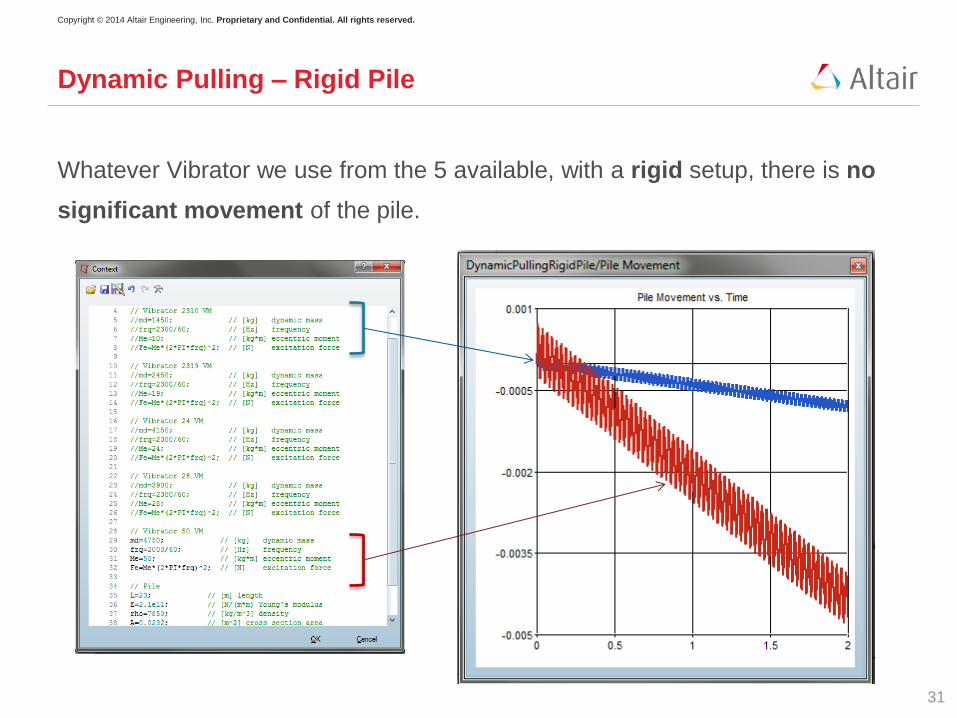
Dynamic Pulling – Rigid Pile
Whatever Vibrator we use from the 5 available, with a rigid setup, there is no
significant movement of the pile.
31

Copyright © 2014 Altair Engineering, Inc. Proprietary and Confidential. All rights reserved.
Dynamic Pulling – Elastic Pile
32

Copyright © 2014 Altair Engineering, Inc. Proprietary and Confidential. All rights reserved.
Dynamic Pulling – Elastic Pile
Simulation results, i.e. the movements of the pile head, center, and foot
versus time, for each available vibrator, are compared.
2310 VM 24 VM 50 VM
Head Center Foot
33

Copyright © 2014 Altair Engineering, Inc. Proprietary and Confidential. All rights reserved.
Dynamic Pulling – Elastic Pile
The pile as a whole is not moving significantly using the vibrators 2310 VM
and 2319 VM.
With the bigger machines 24 VM, 28 VM, and 50 VM the pile as a whole is
moving significantly upwards.
Why ?
A close look reveals, that the 2310 VM and 2319 VM are not powerful enough
to make the pile foot oscillating, such that the averaged (over time) friction
force becomes small, whereas the others make the pile foot clearly
oscillating.
All in all, a good (cost-efficient) choice for the pile extraction job seems to be
the 24 VM.
34

Copyright © 2014 Altair Engineering, Inc. Proprietary and Confidential. All rights reserved.
Conclusions
On the results
Vibrator 24 VM seems to be a good choice for the described pile extraction job.
If a vibrator is used for pile extraction, then pile elasticity does matter. This result
is twofold:
• If pile elasticity is present, then it should be taken into account
• It is easier to pull an elastic pile than a rigid pile
On the approach and tools used
With the Coselica library, it was possible to develop geomechanical simulation
models easily in ScicosPro, and then test various configurations by changing
model parameters.
35


