IOSR Journal of Electronics and Communication Engineering (IOSR-JECE) e-ISSN: 2278-2834,p- ISSN: 2278-8735.Volume 9, Issue 2, Ver. VIII (Mar-Apr. 2014), PP 37-45 www.iosrjournals.org www.iosrjournals.org 37 | Page Modeling IEEE 802.11 DCF with Finite Retry Limits KVP.Sai Praveen and T.Madhavi Department of ECE, GIT, GITAM University, Visakhapatnam, India Abstract: The IEEE 802.11 is the dominating standard for wireless local area networks (WLANs). IEEE 802.11 uses Distributed Coordination Function (DCF) protocol with Binary exponential backoff (BEB) algorithm for packet transmission. In WLANs, the performance metrics such as throughput and end-to-end delay greatly depend on packet transmission procedure. The packet transmission procedure can be represented with a Markov chain model. Till now, several Markov chain models have been developed for evaluating the performance of IEEE 802.11 wireless networks. Yet, these models cannot truthfully calculate the performance of the network. Moreover, the existing models suffer with high packet collisions resulting in degradation of throughput particularly under congested environments. In order to overcome this, a new packet transmission procedure for DCF protocol is introduced in this paper considering both packet retry limits and transmission errors. A mathematical analysis is carried out for transmission probability and the throughput of the network is analyzed. Simulation results show significant improvement in throughput of DCF protocol under basic access and request-to-send/clear-to-send (RTS/CTS) access mechanisms using the proposed model when compared with the existing models Keywords: DCF, IEEE 802.11, Markov chain model, Throughput. . I. Introduction Wireless local area networks (WLANs) have been widely used for high-speed wireless applications. A key element to the IEEE 802.11 success is its simple medium access control (MAC) operation based on distributed coordination function (DCF) protocol. DCF designates two methods for packet transmission: the two-way handshaking method called basic access mechanism as well as four-way handshaking method known as request-to-send/clear-to-send (RTS/CTS) mechanism. Readers can see [1] for data transmission procedures using these mechanisms. Before a node/station tries for first packet transmission, it has to sense the medium. If the medium is found to be idle for a minimum time equal to the distributed inter frame space (DIFS), the packet will be transmitted directly. Otherwise, the packet enters into backoff and randomly sets its backoff timer within the range of the contention window (CW). The backoff timer is decremented by one every slot time the medium is sensed to be idle and it is frozen when medium is sensed busy. When it reaches zero, the node starts the next transmission. When the packet is successfully received, the receiver will send an acknowledgment (ACK) after a time equal to the short inter frame space (SIFS). If no ACK is received, the sending node assumes a collision, then doubles its current CW, randomly resets its backoff timer, and retransmits the packet when the timer reaches again 0. The packet will be discarded if the retry limit reaches its maximum value. This is the main process takes place in packet transmission. This packet transmission procedure can be well represented with a Markov chain model. Several researchers have studied the performance of IEEE 802.11 DCF by developing the two-state Markov chain models. After the landmark work by Giuseppe Bianchi, who provided an analysis of the saturation throughput of the basic 802.11 protocol assuming a two dimensional Markov model at the MAC layer, many papers have followed the address of this behavior of DCF in a variety of traffic loads and channel transmission conditions [2]. Ziouva et al. introduced a post-backoff stage in the model. To increase the accuracy of the results, busy medium conditions are taken into account in [3]. The IEEE 802.11 performance, primarily the throughput, has been studied in number of papers both analytically and by simulation, but none of them consider finite retry limit and post backoff stage in one [4-7]. Chatzimisios et al. analyze the throughput performance and end-to-end delay by considering packet retry limits [4,5]. Daneshgaran et al. presented a Markov model to analyze the throughput considering transmission errors and capture effects over Rayleigh fading channels [8]. When contention level of the network is high their model is very accurate. In [9], Wu et al. follow the same Markov chain model developed by Bianchi and considers frame retry limits to avoid overestimation of the throughput of 802.11. A post-backoff stage is introduced for maximizing the network throughput in saturation conditions [10]. In [11], Sasi Bhushana Rao et al. developed a new model to predict the accurate performance of the network in erroneous channel conditions. In this model, a backoff delay is introduced between successive packet transmissions to reduce the channel capture effect. Similar to Bianchi’s model, the node remains in the last backoff stage until the packet gets transmitted successfully. Using this model, the throughput and delay performance of the network has been greatly improved when compared to the existing models. In this paper, we have modified the Markov chain model presented in [11] considering finite
Transcript
IOSR Journal of Electronics and Communication Engineering (IOSR-JECE)
I. Introduction Wireless local area networks (WLANs) have been widely used for high-speed wireless applications. A
key element to the IEEE 802.11 success is its simple medium access control (MAC) operation based on
distributed coordination function (DCF) protocol. DCF designates two methods for packet transmission: the
two-way handshaking method called basic access mechanism as well as four-way handshaking method known
as request-to-send/clear-to-send (RTS/CTS) mechanism. Readers can see [1] for data transmission procedures
using these mechanisms. Before a node/station tries for first packet transmission, it has to sense the medium. If
the medium is found to be idle for a minimum time equal to the distributed inter frame space (DIFS), the packet
will be transmitted directly. Otherwise, the packet enters into backoff and randomly sets its backoff timer within
the range of the contention window (CW). The backoff timer is decremented by one every slot time the medium
is sensed to be idle and it is frozen when medium is sensed busy. When it reaches zero, the node starts the next
transmission. When the packet is successfully received, the receiver will send an acknowledgment (ACK) after a
time equal to the short inter frame space (SIFS). If no ACK is received, the sending node assumes a collision,
then doubles its current CW, randomly resets its backoff timer, and retransmits the packet when the timer
reaches again 0. The packet will be discarded if the retry limit reaches its maximum value. This is the main
process takes place in packet transmission. This packet transmission procedure can be well represented with a
Markov chain model.
Several researchers have studied the performance of IEEE 802.11 DCF by developing the two-state
Markov chain models. After the landmark work by Giuseppe Bianchi, who provided an analysis of the
saturation throughput of the basic 802.11 protocol assuming a two dimensional Markov model at the MAC
layer, many papers have followed the address of this behavior of DCF in a variety of traffic loads and channel
transmission conditions [2]. Ziouva et al. introduced a post-backoff stage in the model. To increase the accuracy
of the results, busy medium conditions are taken into account in [3]. The IEEE 802.11 performance, primarily
the throughput, has been studied in number of papers both analytically and by simulation, but none of them
consider finite retry limit and post backoff stage in one [4-7]. Chatzimisios et al. analyze the throughput
performance and end-to-end delay by considering packet retry limits [4,5]. Daneshgaran et al. presented a
Markov model to analyze the throughput considering transmission errors and capture effects over Rayleigh
fading channels [8]. When contention level of the network is high their model is very accurate. In [9], Wu et al.
follow the same Markov chain model developed by Bianchi and considers frame retry limits to avoid
overestimation of the throughput of 802.11. A post-backoff stage is introduced for maximizing the network
throughput in saturation conditions [10]. In [11], Sasi Bhushana Rao et al. developed a new model to predict the
accurate performance of the network in erroneous channel conditions. In this model, a backoff delay is
introduced between successive packet transmissions to reduce the channel capture effect. Similar to Bianchi’s
model, the node remains in the last backoff stage until the packet gets transmitted successfully. Using this
model, the throughput and delay performance of the network has been greatly improved when compared to the
existing models. In this paper, we have modified the Markov chain model presented in [11] considering finite
Modeling IEEE 802.11 DCF with finite retry limits
www.iosrjournals.org 38 | Page
retry limits after which the frame is discarded from the transmit queue and a new frame is admitted in the queue.
The parameters such as backoff freezing, packet collision errors and channel error conditions are taken into
account for this proposed model.
The paper is organized as follows. Alterations made to original DCF are specified in Section II. In
Section III, we present the modified Markov chain model and derived the equation for transmission probability.
The throughput analysis is carried out in Section IV and finally concluded in Section V.
II. Alterations Made to Original DCF (i) To reduce the contention among nodes, after successful transmission of a packet at any backoff stage, the
node waits for a random backoff interval to access the channel again. The advantage of this is to avoid the
channel capture. Under saturated conditions, the node selects this interval between (0, W0− 1) at post-
backoff stage where W0 is the initial contention window (CW) size.
(ii) In unsaturated conditions, where the packet arrival follows the Poisson’s process, the node stays in idle
(−1,0) state until the next packet arrives in its queue.
(iii) The packet can be transmitted at any backoff stage when its backoff counter is zero. When the packet
arrives at node’s buffer and when the channel is idle, it goes from state (−1,0) to state (0,0) and transmits
the packet. When the channel is busy, it selects the CW between (0, W0−1) at (0,0) state.
(iv) The packet will be discarded after reaching maximum retry limits (finite retry limit) defined by the
protocol.
III. Implementation of Modified Markov Chain Model Let b(t) and s(t) are the stochastic process representing the backoff timer at time (t) and the backoff
stage (0,…, m), respectively. The backoff delay takes the values (0, 1, …,Wi− 1) where Wi = 2iCWmin. W, W0 and
CWmin can be interchangeable. At the first transmission attempt of a packet, Wi is set equal to CWmin where
CWmin is the minimum contention window size. The contention window will be increased either because of
packet collisions or because of transmission errors since a node cannot distinguish a packet collision from a
transmission error. If collision occurs in any transmission attempt, the contention window size will get doubled.
When this reaches a maximum value CWmax and when the packet transmission fails at this stage (m׳) also, the
node selects the next contention window size as CWmax until the node reaches the maximum backoff stage, m.
When the retry of packet transmission reaches the maximum limit as specified by the protocol, the packet will
be discarded from queue and a new packet waiting for transmission enters the post back off stage. Therefore, the
contention window size is given by (1)
W
WW
m
m
i '
2
2
m'i
m'i
(1)
In order to consider the non-saturated traffic, we define q as the probability of having at least one
packet in the node’s buffer for its transmission. Similar to Bianchi model [2], the key approximation in the
proposed model is that, at each transmission attempt, and irrespective of the number of retransmissions suffered,
each packet collides with constant and independent probability Pcol where Pcol is the conditional probability that
the transmitted packet encounters a collision. It is assumed that transmission errors because of the imperfect
channel can occur with probability Pe and the channel is busy with probability Pb. The collision and
transmission error probabilities are assumed to be statistically independent. Here, the state of each node is
described by {i, k}, where i indicates the backoff stage (0, …, m) and k indicates the backoff delay. Peq is the
equivalent probability of failed transmission that takes into account the need for a new contention window due
to either packet collision (Pcol) or channel errors (Pe) i.e., Peq= Pe + Pcol - Pe Pcol.
1.1 Two-state Modified Markov chain model
The proposed discrete-time Markov chain model considering unsaturated traffic conditions is shown in
Fig. 1. In this model, to avoid the channel capture and to reduce the contention among nodes, after successful
transmission of a packet at any backoff stage, the node waits for a random backoff interval to access the channel
again. Under saturated conditions, the node selects this interval between (0, CWmin) at W-1 stage where CWmin is
the minimum contention window size. The selection of the contention window in the next stage depends on the
backoff algorithm. The packet can be transmitted at any backoff stage when its backoff counter is zero. The
procedure for packet transmission is similar to BEB algorithm except that the delay is introduced between
successive packet transmissions. So, a post-backoff stage (−1, k), }1....0{ 0 Wk with finite retry limits are
considered in the proposed Markov model. Section 3.2 describes the backoff state transitions.
Modeling IEEE 802.11 DCF with finite retry limits
www.iosrjournals.org 39 | Page
1.2 Backoff State Transitions:
(i) The backoff counter decrements when the node senses the channel idle.
bPkikiP 1)}1,(|),{( ),0(),2,0( miWk i (2)
(ii) The backoff counter freezes when the node senses that the channel is busy.
bPkikiP )}1,(|),{( ),0(),1,1( miWk i (3)
(iii) After each successful transmission, the node with a packet in queue goes to post-backoff stage.
0))1(()}0,(|),1{( WqPikP b )1,0( 0 Wk (4)
(iv) After unsuccessful transmission at stage (i −1), the node reschedules a backoff delay in the next stage.
iWPkiP eq1,0)}-(i|),{( ),1(),1,0( miWk i (5)
(v) When the transmission is unsuccessful in all the stages, or after the retry limit is reached, the packet will be
discarded/packet is dropped. In this case backoff mechanism is rescheduled for new packet transmission.
01)}0,(|){(-1, WmkP )1,0( mWk (6)
Fig. 1 Proposed Markov chain model
3.3 Post-Backoff State Transitions: (i) After each successful transmission, the node goes to idle state (−1, 0) when the queue is empty and waits in
that state until the new packet arrives in the queue.
)1)(1()}0,(|)0,1{( qPiP eq ),0( mi (7)
qP 1)}0,1(|)0,1{(
(ii) The node with a packet for transmission, goes to (0, 0) state when the channel is free and then transmits the
packet.
)1()}0,1(|)0,0{( bPqP (8)
(iii) The node with a packet for transmission, selects a backoff stage when the channel is busy.
0
)}0,1(|),0{(W
qPkP b )1,0( 0 Wk (9)
(iv) In the post-backoff stage, the backoff counter decrements when the node senses the channel idle and freezes
when the channel is busy.
)1()1,1(|),1{( bPkkP )2,0( 0 Wk (10)
bPkkP )},1(|),1{( )1,1( 0 Wk
The probability that a node occupies a given state {i, k} at any discrete time slot is bi,k = limt→∞ P{s(t) = i, b(t)
= k} where i, k are integers and −1 ≤ i ≤ m, 0 ≤ k ≤Wi –1. In steady state, the following relations are valid:
0,0,1
bP
P
W
kWb
b
i
eq
i
iki
)1,1();1,1( miWk i (11)
Modeling IEEE 802.11 DCF with finite retry limits
www.iosrjournals.org 40 | Page
0,0,1
bP
Pb
eq
m
eq
om
(12)
0,0,)1(
bP
P
W
kWb
b
m
eq
i
ikm
(13)
In the above Markov chain model, after successful transmission at any backoff stage, the node directly enters
state (−1, 0) when there are no packets to be transmitted and keeps iterating in that state until the arrival of new
packet. The stationary probability to be in state b−1,0 can be evaluated as
0,00,1
1b
q
qb
(14)
After successful transmission at any backoff stage, when the node is ready to transmit the next packet, the node
enters state (−1, k) to provide some backoff delay between these packets to avoid channel capture. So the
stationary probability to be in state b-1,k obtained is
0,0
0
0,1
1
1b
PW
kWqb
b
k
)1,1( 0 Wk (15)
And the stationary probability that the node to be in state b0,k is
0,0
0
0,0
1
)1(b
W
kW
P
qPb
b
bk
(16)
According to probability conservation relation, total probability is equal to one. Therefore
m
i
m
i
W
k
kioi
i
bb1 1
1
1
,, 1
(17)
3.4 Probability of Transmission, τ Let τ be the probability with which a node transmits a packet in a randomly chosen slot time. The node
transmits the packet when the backoff counter reaches the value of zero. Then the equation for τ becomes
m
i eq
i bP
b0
0,00,1
1 (18)
On solving the above equations, τ can be expressed as
'
121
21211212112
112112112211112
2112
'
12121122112
112112112211112
2112
'1'
'1'''
11
mm
)])(P())(PP[q(
)])P(()P)(P[qW()]P)(P([qP)])P()(P(qWP[
q)]q)()(P)(WP)(P[q()]P)(Pq([)]P)(P)(Pq)(([
)P)(Pq(
mm
)]P)(P([qP)])P()(P(qWP[)]P)(Wq([P
q)]q)()(P)(WP)(P[q()]P)(Pq([)]P)(P)(Pq)(([
)P)(Pq(
mm
eq
m
eqeq
mm
eq
m
eqeq
m
eqeqeq
m
eqeqeq
beqeqeqbeqeqb
eqb
m
eqeqeq
m
eqeqeqeq
mm
eq
beqeqeqbeqeqb
eqb
(19)
In the above equation, the transmission probability τ depends on Pcol and Pb. In (19), under saturated traffic
conditions (q→1) and when m = 0, that is when no exponential backoff is considered and assuming the packet
transmission errors are only because of collisions and Pb= 0, τ reduces to
1
2
W (20)
This is similar to the equation for the constant backoff window problem which shows that the transmission
probability is independent of the collision probability. Busy Pb and collision probabilities Pcol are important
parameters in evaluating the performance of IEEE 802.11 system and are given as
n
btr PP )1(1 (21)
1)1(1 n
colP
where n is number of contending nodes. Equations (19), (21) represent a non-linear system with the three
unknowns τ, Pcol and Pb, which can be solved by numerical methods and has a unique solution. Note that Pcol ∈
[0,1], Pb ∈ [0,1] and τ ∈ [0,1].
Modeling IEEE 802.11 DCF with finite retry limits
www.iosrjournals.org 41 | Page
3.5 Frame error probability, Pe The performance analysis of the proposed model is done using the network parameters of IEEE
802.11b protocol since it is easier to compare with the existing models, even though the model suits for any
IEEE 802.11 family. The IEEE 802.11b supports data rates of 1, 2, 5.5 and 11 Mbps. In this, the physical layer
convergence procedure (PLCP) preamble and header are transmitted using differential binary phase shift keying
(DBPSK) modulation at a transmission rate of 1 Mbps. The MAC protocol data unit (MPDU) is transmitted
with the rate depending on the modulation used. Due to imperfect channels, the transmitted frame will get
corrupted and the frame error probability is affected by the bit error probability and the size of the frame.
The frame error probability, Pe is defined as (11)
)1)(1(1 __ errorMACerrorPHYe PPP (23)
where PPHY_error is the physical layer (PHY) overhead error probability and PMAC_error is the MPDU error
probability.
The PHY and MAC layer overhead probabilities depend on the bit error probabilities as given below
824
1_ )1(1 berrorPHY PP (24)
Where Pb1 is the ‘bit error probability’ or probability of error of the PLCP preamble and header (24 bytes)
occurs during the transmission of physical layer overhead
8)28(
2_ )1(1 MSDU
berrorMAC PP (25)
Where Pb2 is the ‘bit error probability’ or probability of error of the MPDU occurs during the transmission of
MAC header (28 bytes) and MAC service data unit (MSDU). The equations of Pb1 and Pb2 can be found in [12].
IV. Throughput Analysis The performance of the wireless communication network can be evaluated in terms of system
throughput, probability of collision and so on. The average throughput is the ratio between the total data
received and the total delay incurred. The core contribution of this paper is analytical evaluation of the system
throughput, by considering non-saturated traffic conditions and effect of channel errors during packet
transmission under Rayleigh fading channel environment. A packet is transmitted successfully when the packet
encounters no collisions and no channel errors are introduced during transmission. In this paper, the throughput
analysis is carried out by considering transmission errors under finite load conditions and compared with the
existing models under basic and RTS/CTS access mechanisms. When the data passes through the
communication channel, it is corrupted by the noise. Unsuccessful transmission occurs when more than one user
simultaneously transmit the packets that collides with each other or the data packets may be corrupted at the
receiver because of erroneous channels. In both the cases, the acknowledgment (ACK) will not be received by
the transmitting node and it reschedules the backoff procedure.
Let the normalized system throughput S, defined as the fraction of time the channel is used to transmit
the payload bits successfully. The expected time per slot E[St] can be calculated by taking the successful
transmission slot time with the probability Ps(1 − Pe), unsuccessful transmission slot time because of collision
with the probability (1 − Ps), unsuccessful transmission slot time because of channel errors with probability
PsTe and idle slot time with probability (1 − Ptr).
Where DIFS is the distributed interframe space period, SIFS is the short interframe space period, TPACKET is the
time taken to transmit the data including PHY and MAC headers. TRTS, TCTS and TACK are the timings required to
transmit RTS, CTS and ACK frames, respectively, and δ is the propagation delay. The ACK_Timeout = SIFS +
TACK +DIFS.
In the literature, many researchers have analysed the performance of the wireless networks under
saturated traffic conditions. On the other hand, the network does not yield best performance at saturated
condition and wide-ranging of research has been undertaken to avoid the network from saturation [13]. So by
considering effects of q and the analysis is done to a random input rate, which creates a more challenging
problem. To analyse the performance of unsaturated wireless networks, a parameter λ is used which represents
the rate at which packets arrive at the node’s buffer from the upper layers and measured in packets per second
(Pkts/s). If the traffic arrives in a Poisson distribution with small buffer size, the probability q can be well
approximated as [8]
][
1 tSEeq
(33)
A more accurate model can be derived upon considering different values of q for each backoff state.
However, a reasonable solution consists in using a mean probability valid for the whole Markov model derived
from E[St]. Now, E[St] can be used to calculate the probability q. The probability for k packet arrivals in a
generic time T is given by
!
)(})({
k
TekTaP
kT (34)
From the above equation, the relation of E[St] and q can be written as
][
1}0][({1 tSE
t eSEaPq
(35)
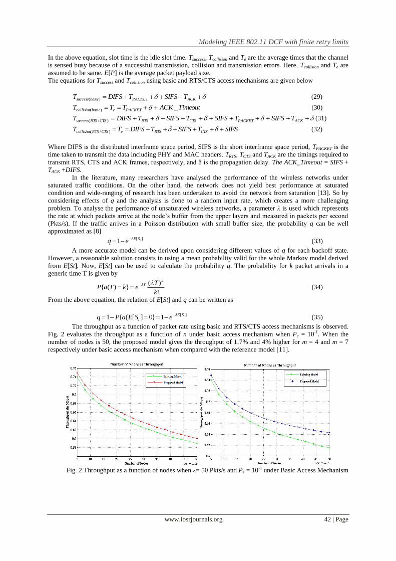
The throughput as a function of packet rate using basic and RTS/CTS access mechanisms is observed.
Fig. 2 evaluates the throughput as a function of n under basic access mechanism when Pe = 10-1
. When the
number of nodes is 50, the proposed model gives the throughput of 1.7% and 4% higher for m = 4 and m = 7
respectively under basic access mechanism when compared with the reference model [11].
Fig. 2 Throughput as a function of nodes when λ= 50 Pkts/s and Pe = 10
-1 under Basic Access Mechanism
Modeling IEEE 802.11 DCF with finite retry limits
www.iosrjournals.org 43 | Page
Fig. 3 Throughput as a function of nodes when λ= 50 Pkts/s and Pe = 10
-3 under Basic Access Mechanism
The throughput as a function of n under basic access mechanism is shown in Fig. 3 when Pe = 10-3
.
The proposed model gives the throughput of 1.6% and 4.5% higher when compared with the reference model
[11] for m = 4 and m = 7 respectively under basic access mechanism when the number of nodes is 50.
Fig. 4 Throughput as a function of nodes when λ= 50 Pkts/s and Pe = 10
-1 under RTS/CTS Mechanism
Fig.4 evaluates the throughput as a function of n under RTS/CTS access mechanism when Pe = 10-1
.
When the number of contending nodes is less than 7, the throughput obtained using the proposed model is
somewhat less compared with the reference model but the performance of the proposed model is better when
compared with the existing model.
The throughput as a function of n under RTS/CTS access mechanism is plotted in Fig. 5 when Pe =10-3
.
It is observed that even under RTS/CTS mechanism the performance of the proposed model is better when
compared with the reference model [11]. Moreover, performance is highly dependent on the network size,
increasing network size results in a decrease in throughput. Notations used for analysis is listed in Table 1 and
the simulation parameters used for performance evaluation is listed in Table 2.
Fig. 5 Throughput as a function of nodes when λ= 50 Pkts/s and Pe = 10
-3 under RTS/CTS Mechanism
Modeling IEEE 802.11 DCF with finite retry limits
www.iosrjournals.org 44 | Page
Table 1 Notations used in analytical analysis
Notation Description
Pb, Ptr Probability that the node at the backoff stage senses the channel busy
Ps Probability of successful transmission
Pcol Probability of transmission collision
Pe Probability of transmission failure due to imperfect channel conditions
Peq Equivalent probability of failed transmission
W0, W Initial contention window size
Τ The probability that a station transmits a packet in a randomly chosen slot time
m Maximum backoff stage
m׳ Contention Window increasing factor
n Number of contending nodes
q The probability of having at least one packet in the stations buffer to transmit
λ Packet arrival rate
E[P] Average packet payload size
E[St] Expected time per slot
DIFS Distributed interframe space period
SIFS Short interframe space period
δ Propagation delay
TACK,TRTS & TCTS Transmission time of ACK, RTS and CTS frames
TPACKET Transmission time of ACK, RTS and CTS frames
Tsuccess Average time that the channel is sensed busy because of successful transmission
Tcollision Average time that the channel is sensed busy due to collisions
Te Average time that the channel is sensed busy due to transmission error
Table 2 Simulation Parameters
Channel Bit Rate 1 Mbps
PHY header 24 bytes
MAC header 28 bytes
RTS 20 bytes + PHY header
CTS 14 bytes + PHY header
ACK 14 bytes + PHY header
DIFS 50 μs
SIFS 10 μs
Slot Time 20 μs
Propagation Delay, δ 1 μs
CWmin (wmin) 31(slots)
CWmax (wmax) 1023(slots)
V. Conclusions In this paper, a new packet transmission procedure for IEEE 802.11 wireless networks is developed for
evaluation of throughput considering finite retry limits. An analytical model is developed to calculate the
transmission probability. The throughput under non-saturated and erroneous channel conditions is analyzed. The
throughput of the proposed model is found to be significantly improved when compared with the existing
model. Finally, the procedure for data transmission explained in this paper enhances the throughput performance
compared with existing DCF protocol used in WLAN.
References [1]. IEEE Standard for Wireless LAN Medium Access Control (MAC) and Physical Layer (PHY) Specifications, IEEE 802.11b, 1999. [2]. G. Bianchi, Performance analysis of the IEEE 802.11 distributed coordination function, IEEE J. on Selected Areas in Comm., Vol.
18(3), pp. 535-547, March 2000.
[3]. Ziouva.E and Antonakopoulos.T, CSMA/CA performance under high traffic conditions throughput and delay analysis, Comput. Commun, 25(3), pp. 313–321, 2002.
[4]. P. Chatzimisios, A.Boucouvalas and Vitsas.V, Throughput and delay analysis of IEEE 802.11 protocol, IWNA, pp. 168–174,2002. [5]. P. Chatzimisios, A.Boucouvalas and Vitsas. V, IEEE 802.11 Packet Delay: A Finite Retry Limit Analysis, Proc. IEEE Globecom, Vol.
2, pp. 950-954, 2003.
[6]. Z.Hadzi Velkov and B.Spasenovski, Saturation Throughput - Delay Analysis of IEEE 802.11 DCF in Fading Channel, IEEE Transactions on Wireless Comm, vol 11(3), pp7803-7802, June2003.
[7]. Z.Hadzi Velkov and B. Spasenovski, On the Capacity of IEEE 802.11DCF with Capture in Multipath-faded Channels, Int. Journal of
Wireless Information Networks, vol. 9(3), Kluwer Academic, July 2002. [8]. F.Daneshgaran, M. Laddomada, F. Mesiti and M. Mondin, Unsaturated Throughput Analysis of IEEE 802.11 in Presence of Non
Ideal Transmission Channel and Capture Effects, IEEE Transactions on Wireless Comm., Vol. 7(4), April 2008.
[9]. H.Wu, Y.Peng, K.Long and Cheng.S, Performance of reliable transport protocol over IEEE 802.11 wireless LAN: Analysis and enhancement. Proc. IEEE INFOCOM, vol. 2, pp. 599–607, 2002.
Modeling IEEE 802.11 DCF with finite retry limits
www.iosrjournals.org 45 | Page
[10]. Anouar. H, and Bonnet.C, Optimal constant-window backoff scheme for IEEE 802.11 DCF in single-hop wireless networks under
finite load conditions”, Wirel. Pers. Commun., 43, pp. 1583–1602, 2007.
[11]. Sasi Bhushana Rao Gottapu, Madhavi Tatineni and MNVSS Kumar, Performance analysis of collision alleviating distributed coordination function protocol in congested wireless networks– a Markov chain analysis, IET Networks, Vol. 2(4). Dec 2013.
[12]. Mahasukhon.P, Hempel.M, Sharif.H, Zhou.T, and Chen.H, BER analysis of 802.11b networks under mobility, IEEE Int. Conf. on
Communications, ICC ’07, pp. 4722–4727, June 2007. [13]. Zhao.H, Wei.J, Wang.S and Xi.Y, Available bandwidth estimation and prediction in ad hoc networks, Mobile Ad-Hoc Networks:
Protocol Design, National University of Defense Technology, China, pp. 61–84, January 2011.