Page 1
“Dedicated to developing new,
innovative solutions.” Ranked in the top 25 SMEs in Europe for FP7 funded projects 2012
www.ctechinnovation.com +44(0)151 347 2900
Modeling of energy efficient continuous
sterilisation of animal by-products (ABP) from
food waste Dr Richard Heslop, Stuart Dalrymple
Page 2
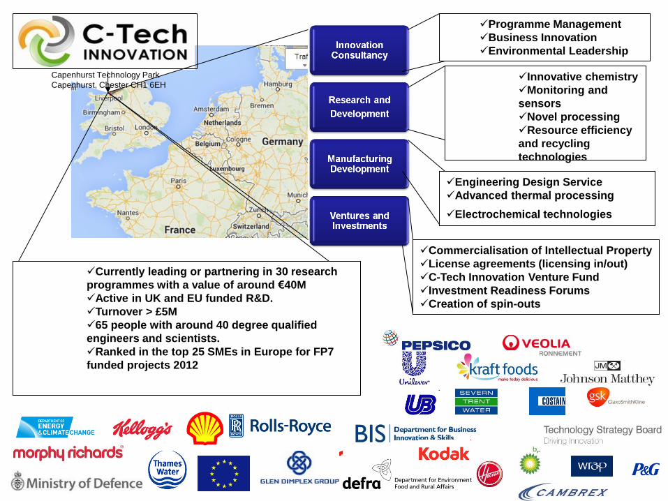
Engineering Design Service
Advanced thermal processing
Electrochemical technologies
Commercialisation of Intellectual Property
License agreements (licensing in/out)
C-Tech Innovation Venture Fund
Investment Readiness Forums
Creation of spin-outs
Capenhurst Technology Park
Capenhurst, Chester CH1 6EH
Programme Management
Business Innovation
Environmental Leadership
Currently leading or partnering in 30 research
programmes with a value of around €40M
Active in UK and EU funded R&D.
Turnover > £5M
65 people with around 40 degree qualified
engineers and scientists.
Ranked in the top 25 SMEs in Europe for FP7
funded projects 2012
Innovative chemistry
Monitoring and
sensors
Novel processing
Resource efficiency
and recycling
technologies
Page 3
“Dedicated to developing new, innovative solutions” Ranked in the top 25 SMEs in Europe for FP7 funded projects 2012
www.ctechinnovation.com +44(0)151 347 2900
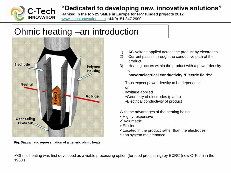
Ohmic heating –an introduction
Ohmic heating was first developed as a viable processing option (for food processing) by ECRC (now C-Tech) in the
1980’s
1) AC Voltage applied across the product by electrodes
2) Current passes through the conductive path of the
product
3) Heating occurs within the product with a power density
of
power=electrical conductivity *Electric field^2
Thus expect power density to be dependent
on
voltage applied
Geometry of electrodes (plates)
Electrical conductivity of product
With the advantages of the heating being:
Highly responsive
Volumetric
Efficient
Located in the product rather than the electrodes=
clean system maintenance
Fig. Diagramatic representation of a generic ohmic heater
Page 4
“Dedicated to developing new, innovative solutions” Ranked in the top 25 SMEs in Europe for FP7 funded projects 2012
www.ctechinnovation.com +44(0)151 347 2900
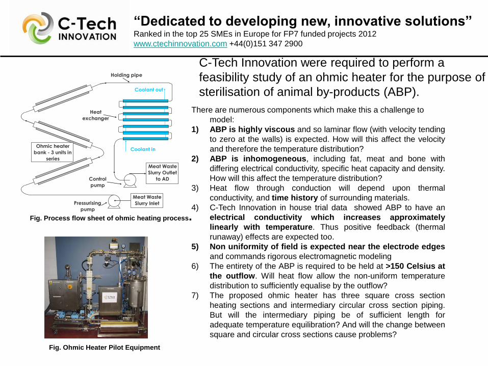
There are numerous components which make this a challenge to
model:
1) ABP is highly viscous and so laminar flow (with velocity tending
to zero at the walls) is expected. How will this affect the velocity
and therefore the temperature distribution?
2) ABP is inhomogeneous, including fat, meat and bone with
differing electrical conductivity, specific heat capacity and density.
How will this affect the temperature distribution?
3) Heat flow through conduction will depend upon thermal
conductivity, and time history of surrounding materials.
4) C-Tech Innovation in house trial data showed ABP to have an
electrical conductivity which increases approximately
linearly with temperature. Thus positive feedback (thermal
runaway) effects are expected too.
5) Non uniformity of field is expected near the electrode edges
and commands rigorous electromagnetic modeling
6) The entirety of the ABP is required to be held at >150 Celsius at
the outflow. Will heat flow allow the non-uniform temperature
distribution to sufficiently equalise by the outflow?
7) The proposed ohmic heater has three square cross section
heating sections and intermediary circular cross section piping.
But will the intermediary piping be of sufficient length for
adequate temperature equilibration? And will the change between
square and circular cross sections cause problems?
C-Tech Innovation were required to perform a
feasibility study of an ohmic heater for the purpose of
sterilisation of animal by-products (ABP).
Heat
exchanger
Holding pipe
Ohmic heater
bank - 3 units in
series
Coolant in
Coolant out
Pressurising
pump
Control
pump
Meat Waste
Slurry Inlet
Meat Waste
Slurry Outlet
to AD
Fig. Process flow sheet of ohmic heating process.
Fig. Ohmic Heater Pilot Equipment
Page 5
“Dedicated to developing new, innovative solutions” Ranked in the top 25 SMEs in Europe for FP7 funded projects 2012
www.ctechinnovation.com +44(0)151 347 2900
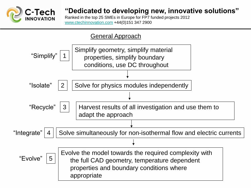
Simplify geometry, simplify material
properties, simplify boundary
conditions, use DC throughout
Solve for physics modules independently
“Simplify”
“Isolate”
Solve simultaneously for non-isothermal flow and electric currents “Integrate”
Evolve the model towards the required complexity with
the full CAD geometry, temperature dependent
properties and boundary conditions where
appropriate
“Evolve”
1
2
4
5
General Approach
Harvest results of all investigation and use them to
adapt the approach
“Recycle” 3
Page 6
“Dedicated to developing new, innovative solutions” Ranked in the top 25 SMEs in Europe for FP7 funded projects 2012
www.ctechinnovation.com +44(0)151 347 2900
Fig. Modules used for the
Multiphysics approach
1. “Import” CAD imported of single heater and complete triple heater design
2. “Simplify” model for preliminary investigation. Take ABP as homogeneous in
dynamic model. consider the ABP as a single material with properties
averaged across the constituents
3. “Model conditions”
Set the inlet at room temperature and the walls as thermally insulated
Employ laminar flow analysis, set flow rate 100kg/hour, set outlet zero.
4. “Temperature dependence” incorporate the temperature dependence of
electrical conductivity from in house trial data
5. “Fine tune” The applied voltage was adjusted until the average temperature at
the outflow was ~190 Celsius
Fig. CAD model of proposed design
Dynamic study – involving ABP taken as homogeneous
Feature of model Combined fluid
Material Macerated raw chicken,
bones and offal
Electrical conductivity
σ(S/m)
0.07+(0.01*T(degC)-25)
Dielectric constant
ε`r
66
Density
kg/m3
1050
Thermal conductivity
κ(Wm-1K-1)
0.5
Heat capacity
C(JK-1)
3500
Table. Material properties
Page 7
“Dedicated to developing new, innovative solutions” Ranked in the top 25 SMEs in Europe for FP7 funded projects 2012
www.ctechinnovation.com +44(0)151 347 2900
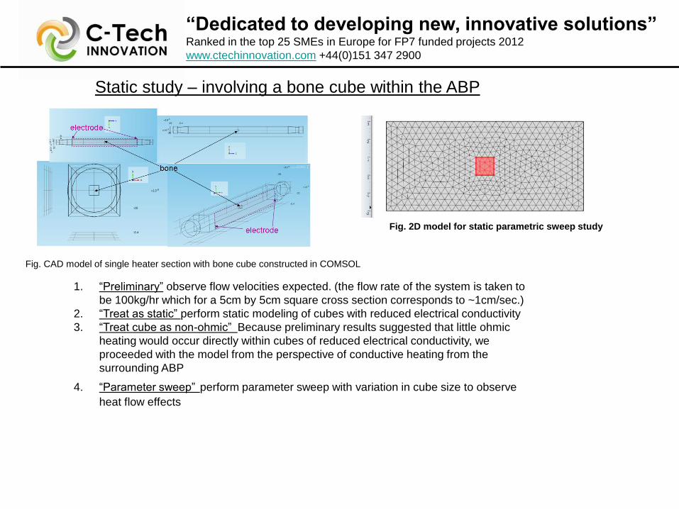
1. “Preliminary” observe flow velocities expected. (the flow rate of the system is taken to
be 100kg/hr which for a 5cm by 5cm square cross section corresponds to ~1cm/sec.)
2. “Treat as static” perform static modeling of cubes with reduced electrical conductivity
3. “Treat cube as non-ohmic” Because preliminary results suggested that little ohmic
heating would occur directly within cubes of reduced electrical conductivity, we
proceeded with the model from the perspective of conductive heating from the
surrounding ABP
4. “Parameter sweep” perform parameter sweep with variation in cube size to observe
heat flow effects
Fig. CAD model of single heater section with bone cube constructed in COMSOL
Static study – involving a bone cube within the ABP
Fig. 2D model for static parametric sweep study
Page 8
“Dedicated to developing new, innovative solutions” Ranked in the top 25 SMEs in Europe for FP7 funded projects 2012
www.ctechinnovation.com +44(0)151 347 2900
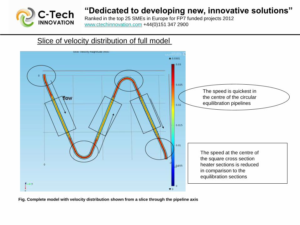
Slice of velocity distribution of full model
The speed is quickest in
the centre of the circular
equilibration pipelines
The speed at the centre of
the square cross section
heater sections is reduced
in comparison to the
equilibration sections
Fig. Complete model with velocity distribution shown from a slice through the pipeline axis
Page 9
“Dedicated to developing new, innovative solutions” Ranked in the top 25 SMEs in Europe for FP7 funded projects 2012
www.ctechinnovation.com +44(0)151 347 2900
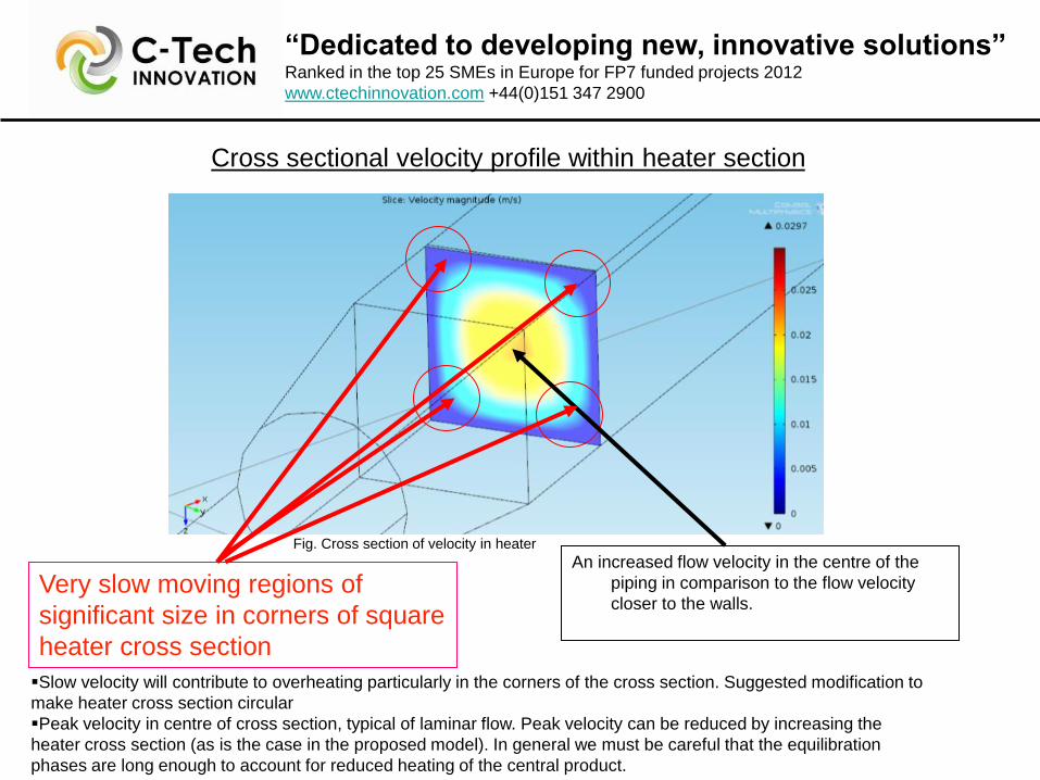
An increased flow velocity in the centre of the
piping in comparison to the flow velocity
closer to the walls.
Very slow moving regions of
significant size in corners of square
heater cross section
Cross sectional velocity profile within heater section
Slow velocity will contribute to overheating particularly in the corners of the cross section. Suggested modification to
make heater cross section circular
Peak velocity in centre of cross section, typical of laminar flow. Peak velocity can be reduced by increasing the
heater cross section (as is the case in the proposed model). In general we must be careful that the equilibration
phases are long enough to account for reduced heating of the central product.
Fig. Cross section of velocity in heater
Page 10
“Dedicated to developing new, innovative solutions” Ranked in the top 25 SMEs in Europe for FP7 funded projects 2012
www.ctechinnovation.com +44(0)151 347 2900
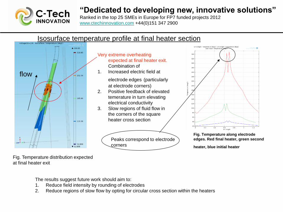
Isosurface temperature profile at final heater section
Fig. Temperature distribution expected
at final heater exit
Very extreme overheating
expected at final heater exit.
Combination of
1. Increased electric field at
electrode edges (particularly
at electrode corners)
2. Positive feedback of elevated
temerature in turn elevating
electrical conductivity
3. Slow regions of fluid flow in
the corners of the square
heater cross section
flow
The results suggest future work should aim to:
1. Reduce field intensity by rounding of electrodes
2. Reduce regions of slow flow by opting for circular cross section within the heaters
Fig. Temperature along electrode
edges. Red final heater, green second
heater, blue initial heater Peaks correspond to electrode
corners
Page 11
“Dedicated to developing new, innovative solutions” Ranked in the top 25 SMEs in Europe for FP7 funded projects 2012
www.ctechinnovation.com +44(0)151 347 2900
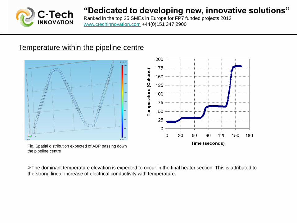
Temperature within the pipeline centre
Fig. Spatial distribution expected of ABP passing down
the pipeline centre
The dominant temperature elevation is expected to occur in the final heater section. This is attributed to
the strong linear increase of electrical conductivity with temperature.
Page 12
“Dedicated to developing new, innovative solutions” Ranked in the top 25 SMEs in Europe for FP7 funded projects 2012
www.ctechinnovation.com +44(0)151 347 2900
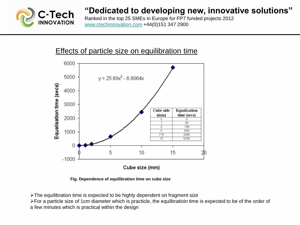
Effects of particle size on equilibration time
The equilibration time is expected to be highly dependent on fragment size
For a particle size of 1cm diameter which is practicle, the equilbratioin time is expected to be of the order of
a few minutes which is practical within the design
Fig. Dependence of equilibration time on cube size
Page 13
“Dedicated to developing new, innovative solutions” Ranked in the top 25 SMEs in Europe for FP7 funded projects 2012
www.ctechinnovation.com +44(0)151 347 2900
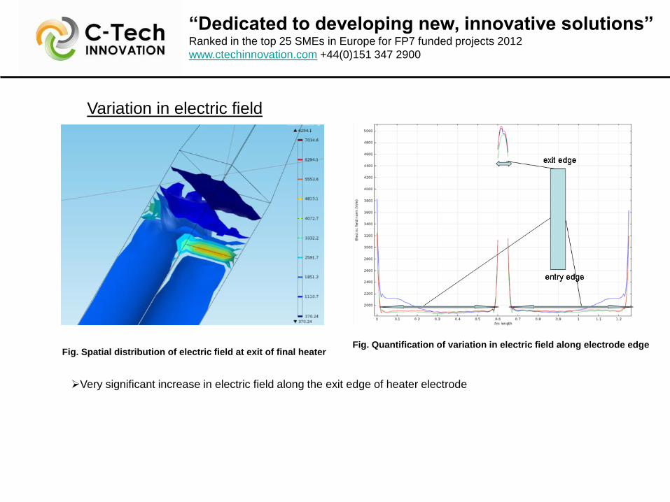
Variation in electric field
Fig. Spatial distribution of electric field at exit of final heater Fig. Quantification of variation in electric field along electrode edge
Very significant increase in electric field along the exit edge of heater electrode
Page 14
“Dedicated to developing new, innovative solutions” Ranked in the top 25 SMEs in Europe for FP7 funded projects 2012
www.ctechinnovation.com +44(0)151 347 2900
Dependence of outflow temperature on votage applied
Fig. Voltage dependence of outflow temperature
Desired outflow temperature
~180-190 Celsius achievable with
practical voltages with the
feasibility study design
There is a strong dependence
of outflow temperature on small
variation in voltage applied, which
commands attention from a
process monitoring and control
perspective
Page 15
“Dedicated to developing new, innovative solutions” Ranked in the top 25 SMEs in Europe for FP7 funded projects 2012
www.ctechinnovation.com +44(0)151 347 2900
Conclusions
Dr. Richard Heslop
[email protected]
+44(0)151 347 2900 In summary…
The feasibility study was successful and has secured further funding for an imminent next
phase
The Multiphysics nature of COMSOL was crucial in solving our expected temperature
distribution.
We have learned that the equilibration regions are adequate to sufficiently reduce the
temperature differential at the outflow.
However, the very significant raising of electric field close to the electrode edges must be
addressed in the next stage of the development process.
We acknowledge excellent technical assistance from COMSOL UK
We are grateful for funding from the Department of Energy and Climate Change, Department
for Environment Food and Rural Affairs, and SBRI
Please feel free to approach me during the rest of the conference, or at C-Tech Innovation