* Corresponding Author MODELING OF OCCUPANT RESPONSE ON SIDE-FACING AIRCRAFT SEATS H M Lankarani * , P K Kishore and A N Murthy National Institute for Aviation Research, Wichita State University, Wichita, KS 67260-0093, USA ABSTRACT This paper addresses the injury and pass/fail criteria as well as the kinematics of occupants on side-facing aircraft seats. To demonstrate equivalent level of safety for these seats compared to the conventional forward-or-aft seats, a number of side-facing seat impact sled tests were conducted using a SID with three-point restraint system on a rigid divan-type couch with a rigid bulkhead in order to maximize the potential for injuries. For multi-occupant tests, a Hybrid II ATD was utilized as a second occupant. Analytical models were developed supporting the test results. A set of parametric studies were then conducted to identify proper restraint systems and seating configurations to protect the occupants. INTRODUCTION In the field of business jets, side-facing seats are quite popular. Many business people, who are the main users of such jets, prefer to relax on these couch type seats during flight and also to sit opposite their interlocutors at meetings, which are held during the flight (Sperber, 1997). Certification of these side-facing aircraft seats (individual and couch type) has presented new challenges to the aircraft industry. Dynamic certification of new side-facing seats (SFS) has become mandatory under Federal Aviation Regulation (FAR) 25.785: "... a side-facing seat must provide the same level of occupant protection as a forward- or aft-facing seat with a safety belt and shoulder harness, and in general provide the protection provision of 25.562." Passengers seated on side-facing seats experience different dynamic response compared to those on forward- or aft-facing seats in an aircraft accident. The regulations established by Amendment 25-64 was developed from a database of forward facing seat test results, and no specific guidelines for the certification of SFS were given. Advisory Circular (AC) 25.562 does not specify a method of compliance nor the injury/pass-fail criteria for side-facing seats. However, AC 25.562-1A, states that, "The injury criteria of 25.562 are not adequate to demonstrate the equivalent safety of side- facing seats. To demonstrate equivalent safety fully in the absence of such specified criteria, the applicant must use other injury criteria which may be derived from the automotive industry, which uses side-impact anthropomorphic test devices or dummies (ATD's)." It is important to note that, although AC25.562 suggests the use of criteria from the automotive industry, the situation for aircraft SFS is quite different from the automotive side impact (Marcus, 1983), as no structure intrudes the side part of the ATD in an aircraft SFS and the nature of soft tissue injury is quite different compared to automotive counterpart. The eventual goals of this research are to identify appropriate injury criteria and to identify a suitable side impact ATD for aircraft SFS certification. In addition a set of design guidelines was sought that would allow a simplified certification procedure using standard forward facing ATD's.
Transcript
*Corresponding Author
MODELING OF OCCUPANT RESPONSE ON SIDE-FACING AIRCRAFT SEATS
H M Lankarani*, P K Kishore and A N Murthy National Institute for Aviation Research, Wichita State University, Wichita, KS 67260-0093, USA
ABSTRACT
This paper addresses the injury and pass/fail criteria as well as the kinematics ofoccupants on side-facing aircraft seats. To demonstrate equivalent level of safety for these seatscompared to the conventional forward-or-aft seats, a number of side-facing seat impact sled testswere conducted using a SID with three-point restraint system on a rigid divan-type couch with arigid bulkhead in order to maximize the potential for injuries. For multi-occupant tests, a Hybrid IIATD was utilized as a second occupant. Analytical models were developed supporting the testresults. A set of parametric studies were then conducted to identify proper restraint systems andseating configurations to protect the occupants.
INTRODUCTION
In the field of business jets, side-facing seats are quite popular. Many business people, whoare the main users of such jets, prefer to relax on these couch type seats during flight and also to sitopposite their interlocutors at meetings, which are held during the flight (Sperber, 1997).Certification of these side-facing aircraft seats (individual and couch type) has presented newchallenges to the aircraft industry. Dynamic certification of new side-facing seats (SFS) hasbecome mandatory under Federal Aviation Regulation (FAR) 25.785: "... a side-facing seat mustprovide the same level of occupant protection as a forward- or aft-facing seat with a safety beltand shoulder harness, and in general provide the protection provision of 25.562." Passengersseated on side-facing seats experience different dynamic response compared to those on forward-or aft-facing seats in an aircraft accident. The regulations established by Amendment 25-64 wasdeveloped from a database of forward facing seat test results, and no specific guidelines for thecertification of SFS were given. Advisory Circular (AC) 25.562 does not specify a method ofcompliance nor the injury/pass-fail criteria for side-facing seats. However, AC 25.562-1A, statesthat, "The injury criteria of 25.562 are not adequate to demonstrate the equivalent safety of side-facing seats. To demonstrate equivalent safety fully in the absence of such specified criteria, theapplicant must use other injury criteria which may be derived from the automotive industry, whichuses side-impact anthropomorphic test devices or dummies (ATD's)." It is important to note that,although AC25.562 suggests the use of criteria from the automotive industry, the situation foraircraft SFS is quite different from the automotive side impact (Marcus, 1983), as no structureintrudes the side part of the ATD in an aircraft SFS and the nature of soft tissue injury is quitedifferent compared to automotive counterpart. The eventual goals of this research are to identifyappropriate injury criteria and to identify a suitable side impact ATD for aircraft SFS certification.In addition a set of design guidelines was sought that would allow a simplified certificationprocedure using standard forward facing ATD's.
2
INJURY AND PASS/FAIL CRITERIA
The side-impact ATD’s used by the automotive industry in dynamic testing includes SideImpact Dummy (SID), European Side Impact Dummy (EuroSID I) and Biofidelic Side ImpactDummy (BioSID) (SAE advisory report 1). The research program described in this paperexamines the response of the SID. The SID is adapted from the Hybrid II 50th percentile male testATD in an attempt to give it biofidelity in lateral impact. University of Michigan TransportResearch Institute (UMTRI) developed it for NHTSA (National Highway Traffic SafetyAdministration) in 1979. Head, neck and neck bracket design is from Hybrid II 50th percentile maletest dummy design. Upper torso was redesigned to give calibrated responses to impacts from theleft or right side with reversal of certain interior components. Arms omitted to prevent flailing andcomplication of torso response, are replaced by foam blocks under the torso jacket. Rib cage hasfive pairs of spring steel ribs with energy absorbing damping material. An adjustable shockabsorber controls motion. Lower torso, modified from Hybrid II, responds to impacts at hiprotation centers from left or right side. The Legs are of Hybrid II design. Major biofidelicdeficiencies are the lack of a shoulder load path, no elasticity in the thoracic compliance, and avery heavy rib mass. Figure 1 shows the SID and its instrumentation (SAE Advisory Report 3).
Figure 1. Side impact ATD SID with its instrumentation used in dynamic testing.
The automotive industry has developed many injury criteria that can be used to evaluate thepotential for occupant injuries in automobile side impact situations. A number of these injurycriteria have been used in the certification of automobile side impact protection. Others have beenused solely for research purposes. These injury criteria along with current FAR 25.562 criterianeed to be evaluated to determine if they are useful as a means of evaluating potential injuries inside facing aircraft seats (SAE Advisory Report 2). A comprehensive list of these potential injurycriteria is listed below.
3
FMVSS 214 Criteria (docket no. 88-06)
Pelvic Acceleration: The potential for pelvis fracture was evaluated using the criterion establishedin FMVSS 214 for side impacts in automotive industry (Shams et al, 1995). The criterion providesfor a limit of 130G for the lateral acceleration of the pelvis. Since SID for which this criterion wasestablished and the Hybrid II and III have identical pelvis construction, the criterion can beappropriately applied to sled tests and simulations using these ATDs.
Thoracic Trauma Index (TTI(d)): The TTI is an acceleration based criterion which uses themaximum value of the near-side rib and spinal acceleration, irrespective of differences in time ofoccurrence, to determine an average acceleration response of the ATD (see Cavanaugh et al, 1990,1994). Thoracic Trauma Index, TTI(d), as measured by a side impact ATD should not exceed 85G.This limit corresponds to an AIS (Abbreviated Injury Scale) of 3 representing serious injury to thethoracic region, and is evaluated as:
TTI(d) = ½ (RIBG + T12G) (1)
where:
RIBG is the larger of the peak acceleration of the upper or the lower rib (chest) in G's,
T12G is the peak acceleration of the 12 thoracic or the lower spine in G's.
Draft ECE 95 Criteria
Viscous Criteria (V*C): It is evaluated from the product of the velocity of deformation and theinstantaneous compression of the chest region of ATD (Lau and Viano, 1986).
V*C =
•
oTDD
max (2)
Where: D is deflection of the rib(s) or chest,
•
D is velocity of deformation of the rib(s) or chest, To is half of undeformed width of the torso or chest. (V*C) is a measure of the soft tissue injury induced by excessive deformation of the chest. It is ratesensitive and corresponds to potential injuries that are not addressed by compression criteria(Viano and Lau, 1988).
Rib Deflection: The lateral compression of rib-to-spine deformation should not exceed 1.6 in.(42 mm).
Research Criteria
Pubic symphysis forces: As measured by the EuroSID ATD, not to exceed 2,250 lb. (10 KN)
Lateral abdominal forces: As measured by the EuroSID ATD, not to exceed 560 lb. (2.5 KN).
Lateral neck moments: As measured by BioSID or Hybrid III, not to exceed 354 in-lb. (40 N-m).
Lateral neck forces: As measured by BioSID or Hybrid III, not to exceed 250 lb. (1.1 KN).
4
FAA Regulation Criteria
Head Injury Criteria (HIC): shall not exceed 1000. The HIC is defined (Gurdjian, 1953, 1964)
max
5.22t
1t1212 dt)t(a
)tt(1
)tt(HIC
∫−−= (3)
Where:a(t) is the instantaneous resultant acceleration of head CG in G's, andt1 and t2 are arbitrary times in the pulse which maximize the HIC value.
Compressive load: Measured between the pelvis and the lumbar column not to exceed 1,500 lb.(7 KN) (for Test 1 condition only).
Femur load: The axial compressive load in each femur of the ATD shall not exceed 2,250 lb.(10KN)
Shoulder Strap Load: For a three-point restraint system, the tension in the shoulder strap must notexceed 1,750 lb. (7.8 KN)
Restraint Retention: Upper torso restraint strap must remain on the occupant’s shoulder during theimpact.
Submarining: Lap safety belt must remain on the occupant pelvis during the impact, and nosubmarining is allowed.
New Criteria Required to Establish an Equivalent Level of Safety
Body-to-body contact: Contact between the head, pelvis, or shoulder area of one ATD on theadjacent seated ATDs is not allowed during the tests conducted in accordance with FAR25.562(b)(1) and (b)(2). Incidental contact of the leg, feet, arms and hand that will not result inincapacitation of the occupants is acceptable. Contact during rebound is allowed. This requirementis due to the lack of information on injuries from body-to-body contact. Since very little is known,the standard simply does not allow the contact.
Body-to-wall/furnishing contact: If the sofa is installed aft of a structure such as an interior wall orfurnishing that may contact the pelvis, upper arm, chest, or head of an occupant seated next to thestructure, a conservative representation of the structure and its stiffness must be included in thetests.
Support: The occupant's pelvis must remain supported by the seat base throughout the test.
SIDE-FACING SEAT RESEARCH PROGRAM
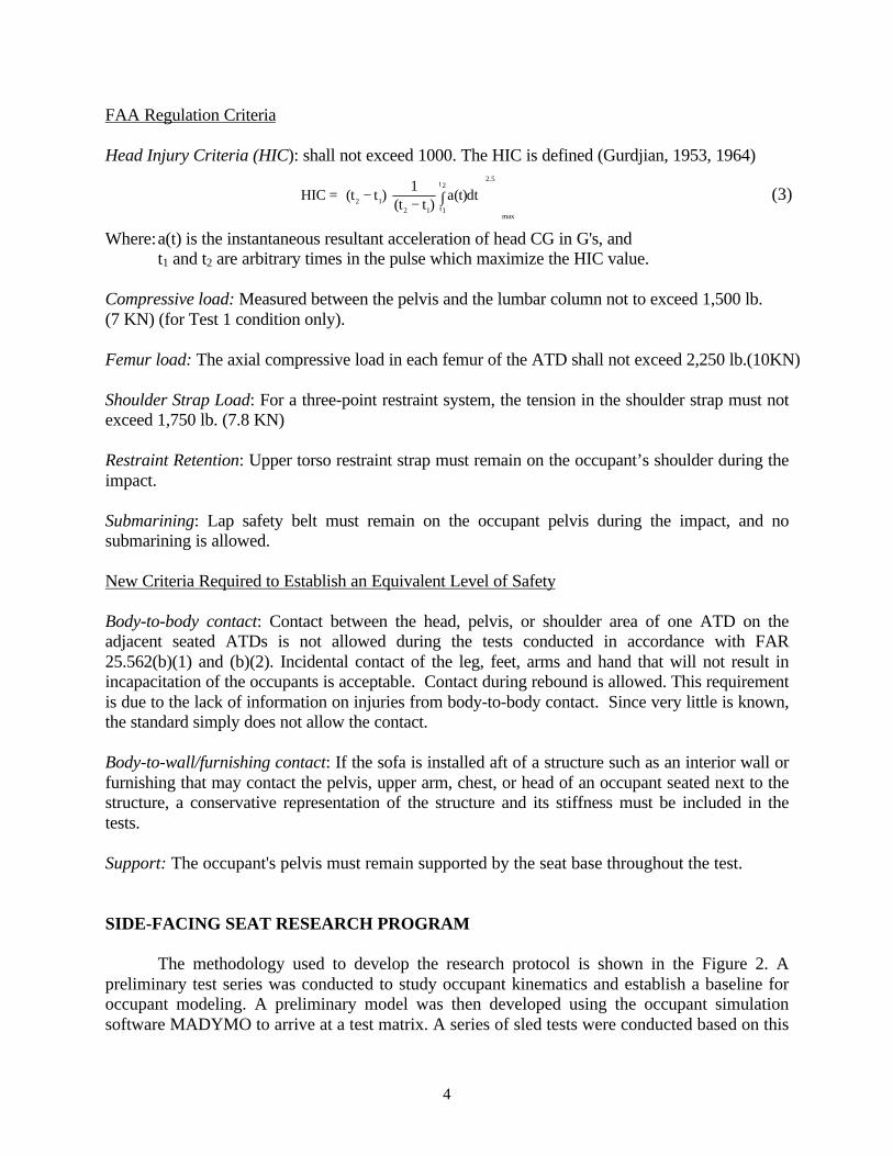
The methodology used to develop the research protocol is shown in the Figure 2. Apreliminary test series was conducted to study occupant kinematics and establish a baseline foroccupant modeling. A preliminary model was then developed using the occupant simulationsoftware MADYMO to arrive at a test matrix. A series of sled tests were conducted based on this
5
at the Civil Aeromedical Institute (CAMI) in Oklahoma City, OK, USA. The results of thesetests were then used to validate the occupant model. A series of parametric studies were thenconducted to analyze the occupant behavior in various environments.
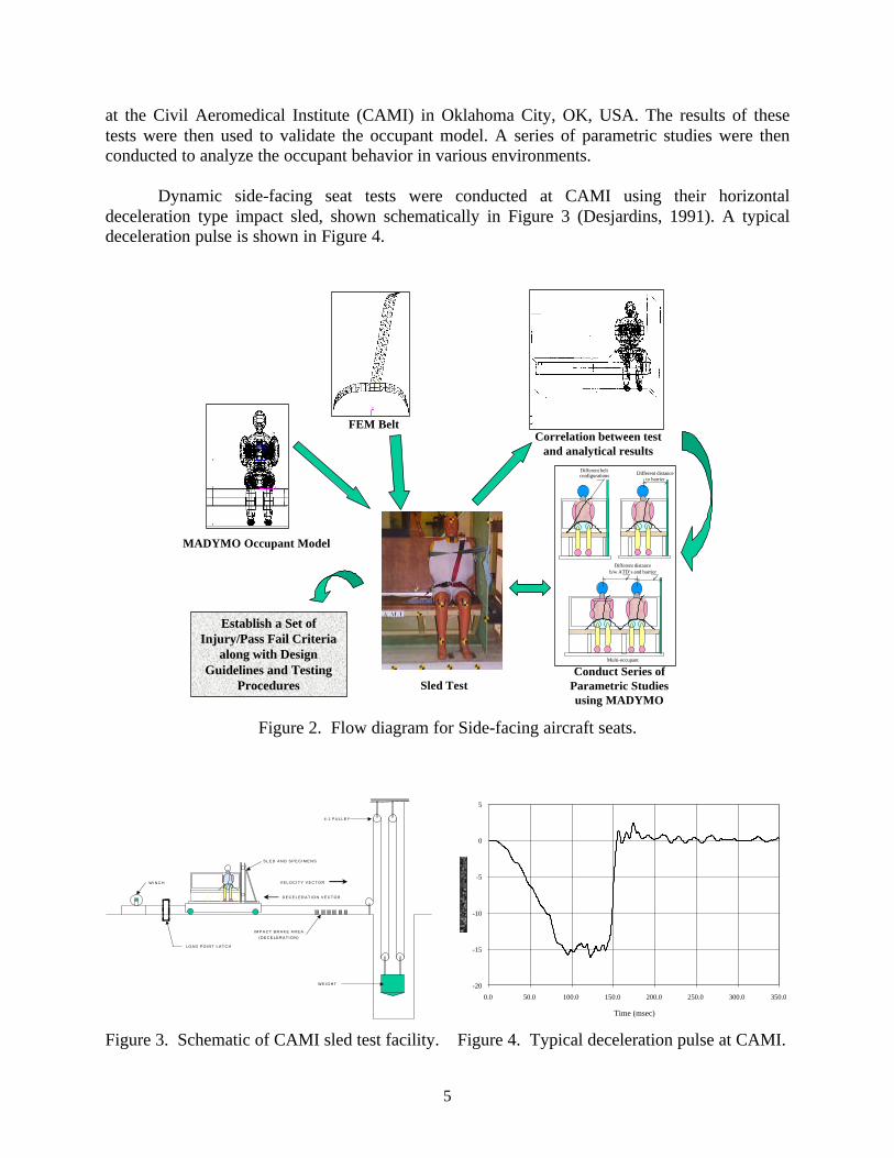
Dynamic side-facing seat tests were conducted at CAMI using their horizontaldeceleration type impact sled, shown schematically in Figure 3 (Desjardins, 1991). A typicaldeceleration pulse is shown in Figure 4.
MADYMO Occupant Model
Correlation between testand analytical results
Establish a Set ofInjury/Pass Fail Criteria
along with DesignGuidelines and Testing
ProceduresConduct Series of
Parametric Studiesusing MADYMO
Sled Test
FEM Belt
Different distanceto barrier
Different beltconfigurations
Different distanceb/w ATD’s and barrier
Multi-occupant
Figure 2. Flow diagram for Side-facing aircraft seats.
W E I G H T
I M P A C T B R A K E A R E A( D E C E L E R A T I O N )
L O A D P O I N T L A T C H
W I N C H
S L E D A N D S P E C I M E N S
V E L O C I T Y V E C T O R
D E C E L E R A T I O N V E C T O R
4 : 1 P U L L E Y
-20
-15
-10
-5
0
5
0.0 50.0 100.0 150.0 200.0 250.0 300.0 350.0
Time (msec)
Figure 3. Schematic of CAMI sled test facility. Figure 4. Typical deceleration pulse at CAMI.
6
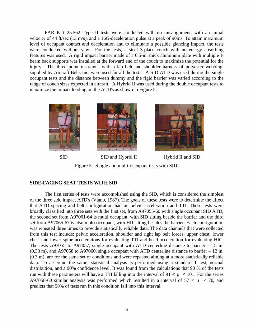
FAR Part 25.562 Type II tests were conducted with no misalignment, with an initialvelocity of 44 ft/sec (13 m/s). and a 16G-deceleration pulse at a peak of 90ms. To attain maximumlevel of occupant contact and deceleration and to eliminate a possible glancing impact, the testswere conducted without yaw. For the tests, a steel 3-place couch with no energy absorbingfeatures was used. A rigid impact barrier made of a 0.5-in. thick aluminum plate with multiple I-beam back supports was installed at the forward end of the couch to maximize the potential for theinjury. The three point restraints, with a lap belt and shoulder harness of polyester webbing,supplied by Aircraft Belts Inc. were used for all the tests. A SID ATD was used during the singleoccupant tests and the distance between dummy and the rigid barrier was varied according to therange of couch sizes expected in aircraft. A Hybrid II was used during the double occupant tests tomaximize the impact loading on the ATD's as shown in Figure 5.
SID SID and Hybrid II Hybrid II and SID
Figure 5. Single and multi-occupant tests with SID.
SIDE-FACING SEAT TESTS WITH SID
The first series of tests were accomplished using the SID, which is considered the simplestof the three side impact ATD's (Viano, 1987). The goals of these tests were to determine the affectthat ATD spacing and belt configuration had on pelvic acceleration and TTI. These tests werebroadly classified into three sets with the first set, from A97055-60 with single occupant SID ATD;the second set from A97061-64 is multi occupant, with SID sitting beside the barrier and the thirdset from A97065-67 is also multi occupant, with HII sitting besides the barrier. Each configurationwas repeated three times to provide statistically reliable data. The data channels that were collectedfrom this test include: pelvic acceleration, shoulder and right lap belt forces, upper chest, lowerchest and lower spine accelerations for evaluating TTI and head acceleration for evaluating HIC.The tests A97055 to A97057, single occupant with ATD centerline distance to barrier – 15 in.(0.38 m), and A97058 to A97060, single occupant with ATD centerline distance to barrier – 12 in.(0.3 m), are for the same set of conditions and were repeated aiming at a more statistically reliabledata. To ascertain the same, statistical analysis is performed using a standard T test, normaldistribution, and a 90% confidence level. It was found from the calculations that 90 % of the testsrun with these parameters will have a TTI falling into the interval of 91 < µ < 101. For the seriesA97058-60 similar analysis was performed which resulted in a interval of 57 < µ < 70, andpredicts that 90% of tests run in this condition fall into this interval.
7
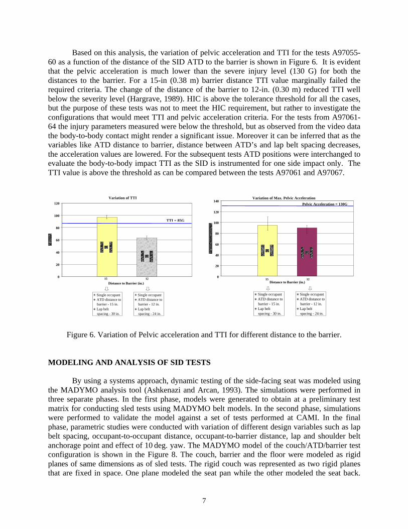
Based on this analysis, the variation of pelvic acceleration and TTI for the tests A97055-60 as a function of the distance of the SID ATD to the barrier is shown in Figure 6. It is evidentthat the pelvic acceleration is much lower than the severe injury level (130 G) for both thedistances to the barrier. For a 15-in (0.38 m) barrier distance TTI value marginally failed therequired criteria. The change of the distance of the barrier to 12-in. (0.30 m) reduced TTI wellbelow the severity level (Hargrave, 1989). HIC is above the tolerance threshold for all the cases,but the purpose of these tests was not to meet the HIC requirement, but rather to investigate theconfigurations that would meet TTI and pelvic acceleration criteria. For the tests from A97061-64 the injury parameters measured were below the threshold, but as observed from the video datathe body-to-body contact might render a significant issue. Moreover it can be inferred that as thevariables like ATD distance to barrier, distance between ATD’s and lap belt spacing decreases,the acceleration values are lowered. For the subsequent tests ATD positions were interchanged toevaluate the body-to-body impact TTI as the SID is instrumented for one side impact only. TheTTI value is above the threshold as can be compared between the tests A97061 and A97067.
Variation of TTI
0
20
40
60
80
100
120
Distance to Barrier (in.)15
TTI = 85G
12
T Single occupantT ATD distance to barrier - 15 in.T Lap belt spacing - 30 in.
T Single occupantT ATD distance to barrier - 12 in.T Lap belt spacing - 24 in.
Variation of Max. Pelvic Acceleration
0
20
40
60
80
100
120
140
Distance to Barrier (in.)
Pelvic Acceleration = 130G
15 12
T Single occupantT ATD distance to barrier - 15 in.T Lap belt spacing - 30 in.
T Single occupantT ATD distance to barrier - 12 in.T Lap belt spacing - 24 in.
Figure 6. Variation of Pelvic acceleration and TTI for different distance to the barrier.
MODELING AND ANALYSIS OF SID TESTS
By using a systems approach, dynamic testing of the side-facing seat was modeled usingthe MADYMO analysis tool (Ashkenazi and Arcan, 1993). The simulations were performed inthree separate phases. In the first phase, models were generated to obtain at a preliminary testmatrix for conducting sled tests using MADYMO belt models. In the second phase, simulationswere performed to validate the model against a set of tests performed at CAMI. In the finalphase, parametric studies were conducted with variation of different design variables such as lapbelt spacing, occupant-to-occupant distance, occupant-to-barrier distance, lap and shoulder beltanchorage point and effect of 10 deg. yaw. The MADYMO model of the couch/ATD/barrier testconfiguration is shown in the Figure 8. The couch, barrier and the floor were modeled as rigidplanes of same dimensions as of sled tests. The rigid couch was represented as two rigid planesthat are fixed in space. One plane modeled the seat pan while the other modeled the seat back.
8
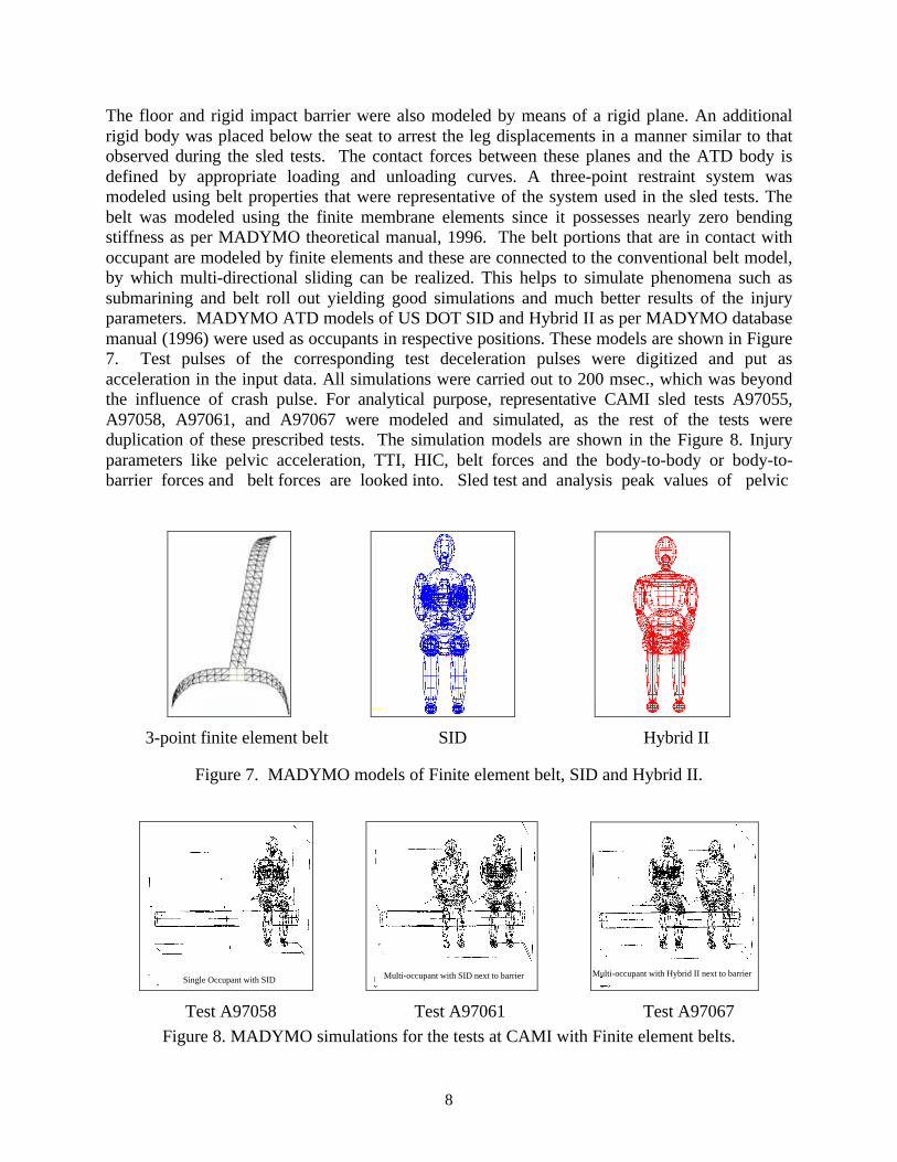
The floor and rigid impact barrier were also modeled by means of a rigid plane. An additionalrigid body was placed below the seat to arrest the leg displacements in a manner similar to thatobserved during the sled tests. The contact forces between these planes and the ATD body isdefined by appropriate loading and unloading curves. A three-point restraint system wasmodeled using belt properties that were representative of the system used in the sled tests. Thebelt was modeled using the finite membrane elements since it possesses nearly zero bendingstiffness as per MADYMO theoretical manual, 1996. The belt portions that are in contact withoccupant are modeled by finite elements and these are connected to the conventional belt model,by which multi-directional sliding can be realized. This helps to simulate phenomena such assubmarining and belt roll out yielding good simulations and much better results of the injuryparameters. MADYMO ATD models of US DOT SID and Hybrid II as per MADYMO databasemanual (1996) were used as occupants in respective positions. These models are shown in Figure7. Test pulses of the corresponding test deceleration pulses were digitized and put asacceleration in the input data. All simulations were carried out to 200 msec., which was beyondthe influence of crash pulse. For analytical purpose, representative CAMI sled tests A97055,A97058, A97061, and A97067 were modeled and simulated, as the rest of the tests wereduplication of these prescribed tests. The simulation models are shown in the Figure 8. Injuryparameters like pelvic acceleration, TTI, HIC, belt forces and the body-to-body or body-to-barrier forces and belt forces are looked into. Sled test and analysis peak values of pelvic
3-point finite element belt SID Hybrid II
Figure 7. MADYMO models of Finite element belt, SID and Hybrid II.
Test A97058 Test A97061 Test A97067
Figure 8. MADYMO simulations for the tests at CAMI with Finite element belts.
Multi-occupant with SID next to barrierSingle Occupant with SIDMulti-occupant with Hybrid II next to barrier
9
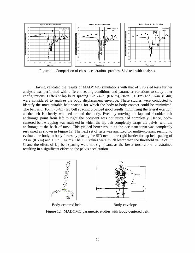
acceleration and TTI show reasonable agreement as can be read from Figure 9. Similarly, theprofiles of pelvic accelerations were compared and showed reasonable agreement, during thepeak acceleration period and is less than the threshold value of 130G in all the cases as shown inFigure 10. The Figure 11 shows the comparison of upper, lower chest and spine accelerationprofiles for the test A97058 as a typical test. The accelerations of the upper and lower chest arehigher when compared to MADYMO, whereas the spine acceleration is lower for this testcondition. Overall the TTI values fairly agrees with all the test conditions (within 10%) forwhich these three accelerations are used.
Further analytical studies are conducted to study the probable contact forces between thebarrier and occupant in case of single occupant and contact force between the occupants in caseof multiple occupants. This will provide the information forehand to analyze the potentialinjuries pertaining to this type of seating. It can be inferred that the forces decrease as the lap beltspacing and ATD distance from barrier decreases. Simulations were extended to study the effectof 10-deg yaw on the system. No roll out is possibly observed and pelvic accelerations and TTIwere further lowered. Although analysis shows reasonable correlation with the tests, severalparameters including the belt properties, slipping and friction, etc. could affect the results.
9387 90
55
113
7684
40
0
20
40
60
80
100
120
140
A97055 A97058 A97061 A97067
Pelvic Acceleration = 130G
CAMI
MADYMO
MADYMO
CAMI
MADYMO
CAMI
MADYMO
CAMI
MADYMO
T Single occupantT ATD distance to barrier - 15 in.T Lap belt spacing - 30 in.
T Single occupantT ATD distance to barrier - 12 in.T Lap belt spacing - 24 in.
T Multi-occupantT ATD distance to barrier - 12 in.T Distance b/w ATD’s - 24 in.T SID next to barrier.
T Multi-occupantT ATD distance to barrier - 12 in.T Distance b/w ATD’s - 24 in.T HII next to barrier.
T Single occupantT ATD distance to barrier - 15 in.T Lap belt spacing - 30 in.
T Single occupantT ATD distance to barrier - 12 in.T Lap belt spacing - 24 in.
94
61 62
104
83
57
70
110
0
20
40
60
80
100
120
A97055 A97058 A97061 A97067
TTI = 85 G
CAMI
MADYMO
CAMI
MADYMO
CAMI
MADYMO
CAMI
MADYMO
CAMI
MADYMO
T Multi-occupantT ATD distance to barrier - 12 in.T Distance b/w ATD’s - 24 in.T SID next to barrier.
T Multi-occupantT ATD distance to barrier - 12 in.T Distance b/w ATD’s - 24 in.T HII next to barrier.
Figure 9. Comparison of pelvic acceleration and TTI peak values: Sled test with analysis.
TEST A97055
-120
-90
-60
-30
0
30
60
0 25 50 75 100 125 150 175 200
Time (msec)
CAMI
MADYMO
TEST A97058
-120
-90
-60
-30
0
30
60
0 25 50 75 100 125 150 175 200Time (msec)
CAMI
MADYMO
TEST A97061
-120
-90
-60
-30
0
30
60
0 25 50 75 100 125 150 175 200Time (msec)
CAMI
MADYMO
Figure 10. Comparison of pelvic acceleration profile: Sled test with analysis.
10
Upper Rib Y- Acceleration
-80
-70
-60
-50
-40
-30
-20
-10
0
10
20
30
0 25 50 75 100 125 150 175 200
Time (msec)
MADYMOCAMI
Lower Rib Y- Acceleration
-70
-60
-50
-40
-30
-20
-10
0
10
20
30
0 25 50 75 100 125 150 175 200
Time (msec)
MADYMOCAMI
Lower Spine Y - Acceleration
-70
-60
-50
-40
-30
-20
-10
0
10
20
30
0 25 50 75 100 125 150 175 200
Time (msec)
MADYMOCAMI
Figure 11. Comparison of chest accelerations profiles: Sled test with analysis.
Having validated the results of MADYMO simulations with that of SFS sled tests furtheranalysis was performed with different seating conditions and parameter variations to study otherconfigurations. Different lap belts spacing like 24-in. (0.61m), 20-in. (0.51m) and 16-in. (0.4m)were considered to analyze the body displacement envelope. These studies were conducted toidentify the most suitable belt spacing for which the body-to-body contact could be minimized.The belt with 16-in. (0.4m) lap belt spacing provided good results minimizing the lateral exertion,as the belt is closely wrapped around the body. Even by moving the lap and shoulder beltanchorage point from left to right the occupant was not restrained completely. Hence, body-centered belt wrapping was analyzed in which the lap belt completely wraps the pelvis, with theanchorage at the back of torso. This yielded better result, as the occupant torso was completelyrestrained as shown in Figure 12. The next set of tests was analyzed for multi-occupant seating, toevaluate the body-to-body forces by placing the SID next to the rigid barrier for lap belt spacing of20 in. (0.5 m) and 16 in. (0.4 m). The TTI values were much lower than the threshold value of 85G and the effect of lap belt spacing were not significant, as the lower torso alone is restrainedresulting in a significant effect on the pelvis acceleration.
0.54m
0.39m
Body-centered belt Body-envelope
Figure 12. MADYMO parametric studies with Body-centered belt.
11
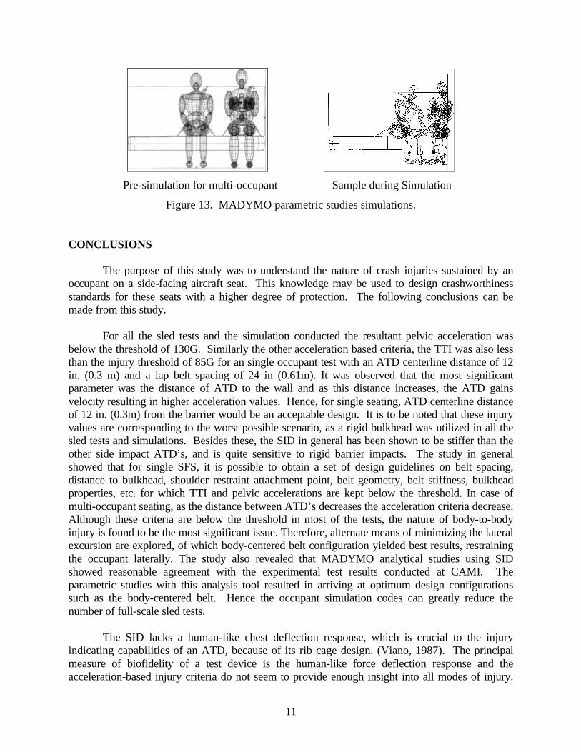
Pre-simulation for multi-occupant Sample during Simulation
Figure 13. MADYMO parametric studies simulations.
CONCLUSIONS
The purpose of this study was to understand the nature of crash injuries sustained by anoccupant on a side-facing aircraft seat. This knowledge may be used to design crashworthinessstandards for these seats with a higher degree of protection. The following conclusions can bemade from this study.
For all the sled tests and the simulation conducted the resultant pelvic acceleration wasbelow the threshold of 130G. Similarly the other acceleration based criteria, the TTI was also lessthan the injury threshold of 85G for an single occupant test with an ATD centerline distance of 12in. (0.3 m) and a lap belt spacing of 24 in (0.61m). It was observed that the most significantparameter was the distance of ATD to the wall and as this distance increases, the ATD gainsvelocity resulting in higher acceleration values. Hence, for single seating, ATD centerline distanceof 12 in. (0.3m) from the barrier would be an acceptable design. It is to be noted that these injuryvalues are corresponding to the worst possible scenario, as a rigid bulkhead was utilized in all thesled tests and simulations. Besides these, the SID in general has been shown to be stiffer than theother side impact ATD’s, and is quite sensitive to rigid barrier impacts. The study in generalshowed that for single SFS, it is possible to obtain a set of design guidelines on belt spacing,distance to bulkhead, shoulder restraint attachment point, belt geometry, belt stiffness, bulkheadproperties, etc. for which TTI and pelvic accelerations are kept below the threshold. In case ofmulti-occupant seating, as the distance between ATD’s decreases the acceleration criteria decrease.Although these criteria are below the threshold in most of the tests, the nature of body-to-bodyinjury is found to be the most significant issue. Therefore, alternate means of minimizing the lateralexcursion are explored, of which body-centered belt configuration yielded best results, restrainingthe occupant laterally. The study also revealed that MADYMO analytical studies using SIDshowed reasonable agreement with the experimental test results conducted at CAMI. Theparametric studies with this analysis tool resulted in arriving at optimum design configurationssuch as the body-centered belt. Hence the occupant simulation codes can greatly reduce thenumber of full-scale sled tests.
The SID lacks a human-like chest deflection response, which is crucial to the injuryindicating capabilities of an ATD, because of its rib cage design. (Viano, 1987). The principalmeasure of biofidelity of a test device is the human-like force deflection response and theacceleration-based injury criteria do not seem to provide enough insight into all modes of injury.
12
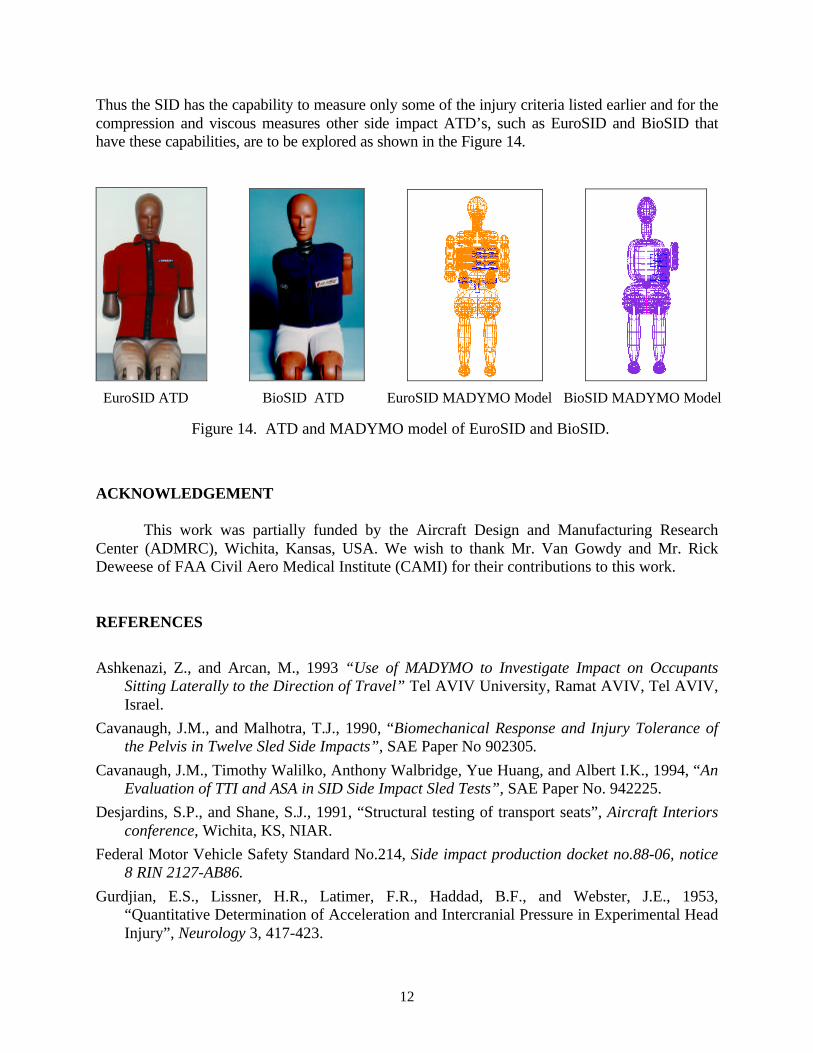
Thus the SID has the capability to measure only some of the injury criteria listed earlier and for thecompression and viscous measures other side impact ATD’s, such as EuroSID and BioSID thathave these capabilities, are to be explored as shown in the Figure 14.
EuroSID ATD BioSID ATD EuroSID MADYMO Model BioSID MADYMO Model
Figure 14. ATD and MADYMO model of EuroSID and BioSID.
ACKNOWLEDGEMENT
This work was partially funded by the Aircraft Design and Manufacturing ResearchCenter (ADMRC), Wichita, Kansas, USA. We wish to thank Mr. Van Gowdy and Mr. RickDeweese of FAA Civil Aero Medical Institute (CAMI) for their contributions to this work.
REFERENCES
Ashkenazi, Z., and Arcan, M., 1993 “Use of MADYMO to Investigate Impact on OccupantsSitting Laterally to the Direction of Travel” Tel AVIV University, Ramat AVIV, Tel AVIV,Israel.
Cavanaugh, J.M., and Malhotra, T.J., 1990, “Biomechanical Response and Injury Tolerance ofthe Pelvis in Twelve Sled Side Impacts”, SAE Paper No 902305.
Cavanaugh, J.M., Timothy Walilko, Anthony Walbridge, Yue Huang, and Albert I.K., 1994, “AnEvaluation of TTI and ASA in SID Side Impact Sled Tests”, SAE Paper No. 942225.
Desjardins, S.P., and Shane, S.J., 1991, “Structural testing of transport seats”, Aircraft Interiorsconference, Wichita, KS, NIAR.
Federal Motor Vehicle Safety Standard No.214, Side impact production docket no.88-06, notice8 RIN 2127-AB86.
Gurdjian, E.S., Lissner, H.R., Latimer, F.R., Haddad, B.F., and Webster, J.E., 1953,“Quantitative Determination of Acceleration and Intercranial Pressure in Experimental HeadInjury”, Neurology 3, 417-423.
13
Gurdjian, E.S., Roberts, V.L., Thomas, L.M.,1964, “Tolerance Curves of Acceleration andIntercranial Pressure and Protective Index in Experimental Head Injury”, J. of Trauma 6,600.
Hargrav, M.W., Hansen, A.G., and Hinch, J.A., 1989, “A Summary of Recent Side impactResearch conducted by the Federal Highway Administration”, SAE Paper No. 890377.
Lan, V.I., and Viano, D.C., 1986 “The Viscous Criteria-Bases and Applications of an InjurySeverity Index for Soft Tissues”, SAE Paper No. 861882, 31st STAPP car crash conference,Warrendale, Pennsylvania.
MADYMO Database Manual Version 5.2, 1996, TNO, Delft, Netherlands.
MADYMO Theoretical manual, Version 5.2, 1996, TNO, Delft, Netherlands.
Marcus, J.H., Morgan, R.M., Eppinger, R.H., Kallieris, D., Mattern, R., and Schmidt, G., 1983,“Human Response to and Injury from Lateral Impact”, SAE Paper No. 831634.
SAE Advisory Report 1 Chapter 2 “Adult dummies: past and present”.
SAE Advisory Report 3 Chapter 6 “Instrumentation and Data Acquisition”.
Sperber, M., Schuller, E., Schroth, C.J., 1997, “Crashworthiness of Side-Facing SeatingPositions in Aircrafts, Biodynamics Stresses and Maximum Strain Criterion”, SAE PaperNo. 971456 Corporate and regional aviation meeting and exposition, Wichita.
Viano, D.C and Lau, I.V., 1988, “A Viscous Tolerance Criterion for Soft Tissue InjuryAssessment”, J. Biomechanics Vol. No.5, pp 387-399.
Viano, D.C., 1987, “Evaluation of the SID dummy criterion for side impact testing”, 31st STAPPcar crash conference, SAE Paper No #872208, Warrendale, Pennsylvania.