Modeling of Strata Gas Liberation into the Mine Drifts with Time-Dependent Ventilation George Danko, Davood Bahrami, and Jon Fox University of Nevada, Reno, Reno, NV Date: February 26, 2013 Location: Denver, CO SME Annual Meeting
Transcript
Modeling of Strata Gas Liberation into the Mine Drifts with Time-Dependent Ventilation
George Danko, Davood Bahrami, and Jon Fox University of Nevada, Reno, Reno, NV
Date: February 26, 2013
Location: Denver, CO SME Annual Meeting
Outline
• Introduction • Coupled transient transport processes • Response changes in ventilation to flow
control in a large-scale mine • Response to barometric pressure variation • Conclusions
2
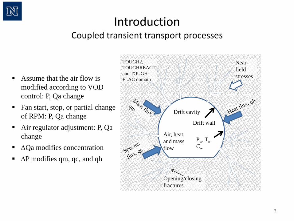
Introduction Coupled transient transport processes
3
TOUGH2, TOUGHREACT, and TOUGH-FLAC domain
Near-field stresses
Opening/closing fractures
Drift cavity
Drift wall
Air, heat, and mass flow
Pw, Tw, Cw
Assume that the air flow is modified according to VOD control: P, Qa change
Fan start, stop, or partial change of RPM: P, Qa change
Air regulator adjustment: P, Qa change
∆Qa modifies concentration ∆P modifies qm, qc, and qh
4
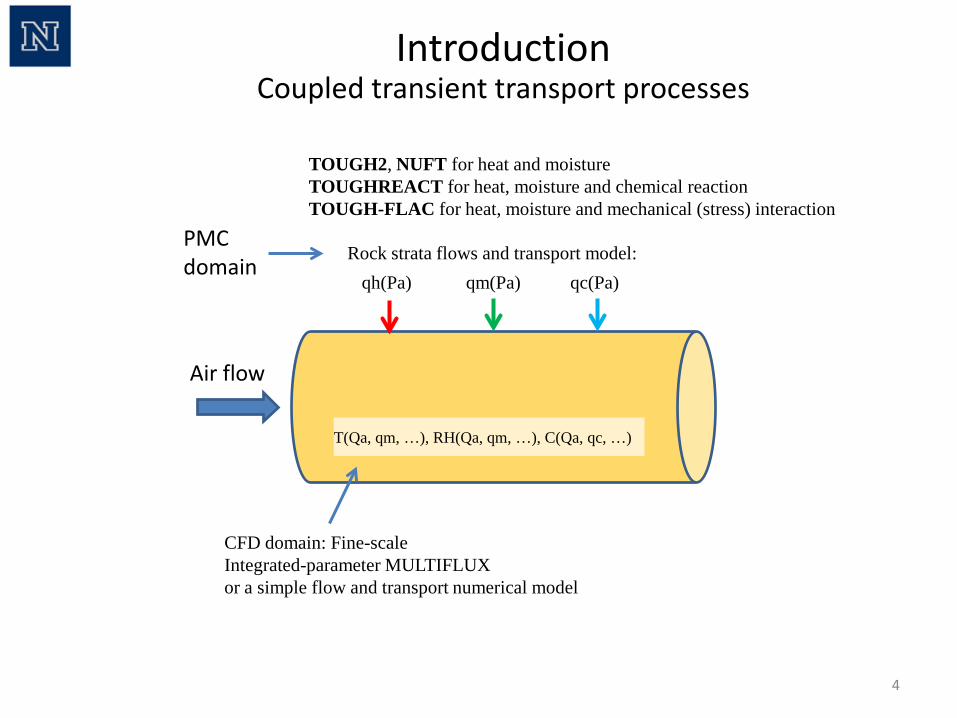
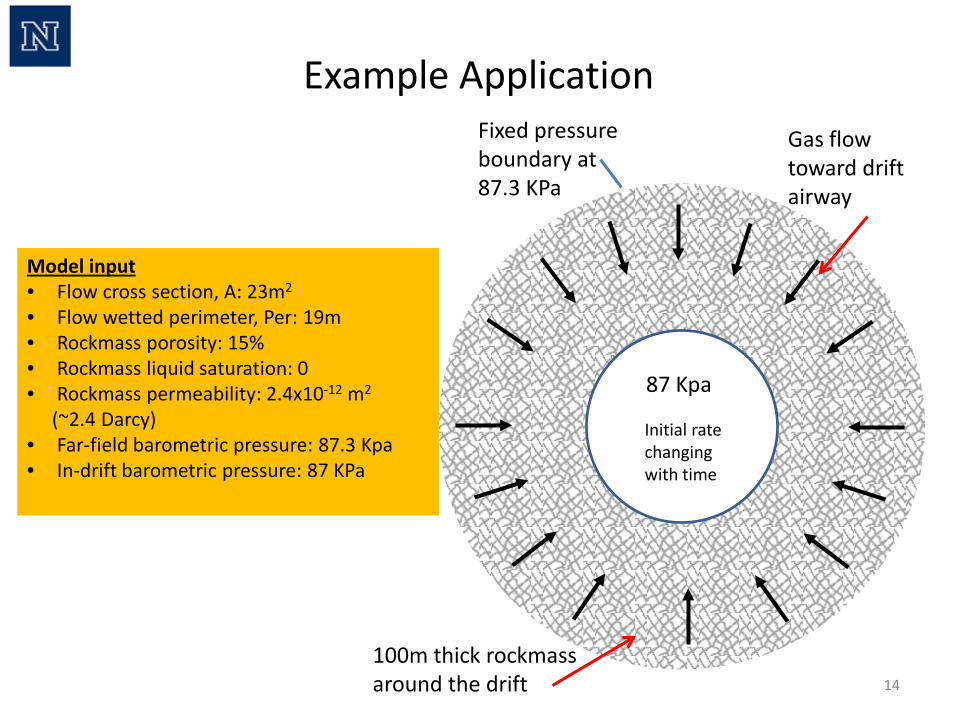
qh(Pa) qm(Pa) qc(Pa) Rock strata flows and transport model:
T(Qa, qm, …), RH(Qa, qm, …), C(Qa, qc, …)
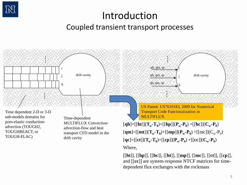
Introduction Coupled transient transport processes
PMC domain
TOUGH2, NUFT for heat and moisture TOUGHREACT for heat, moisture and chemical reaction TOUGH-FLAC for heat, moisture and mechanical (stress) interaction
CFD domain: Fine-scale Integrated-parameter MULTIFLUX or a simple flow and transport numerical model
Air flow
Time dependent 2-D or 3-D sub-models domains for poro-elastic conduction-advection (TOUGH2, TOUGHREACT, or TOUGH-FLAC)
Time-dependent MULTIFLUX Convection-advection-flow and heat transport CFD model in the drift cavity
. . . .
. . . . i
j
k
drift cavity
5
. . . .
. . . . i
j
k
qh, qm, qc
qh, qm, qc
qh, qm, qc
[qh]=[[ht]](Tw-T0)+[[hp]](Pw-P0) +[[hc]](Cw-P0) [qm]=[[mt]](Tw-T0)+[[mp]](Pw-P0) +[[mc]](Cw-P0) [qc]=[[ct]](Tw-T0)+[[cp]](Pw-P0) +[[cc]](Cw-P0) Where, [[ht]], [[hp]], [[hc]], [[ht]], [[mp]], [[mc]], [[ct]], [[cp]], and [[cc]] are system-response NTCF matrices for time-dependent flux exchanges with the rockmass
drift cavity
US Patent: US7610183, 2009 for Numerical Transport Code Funcionalization in MULTIFLUX
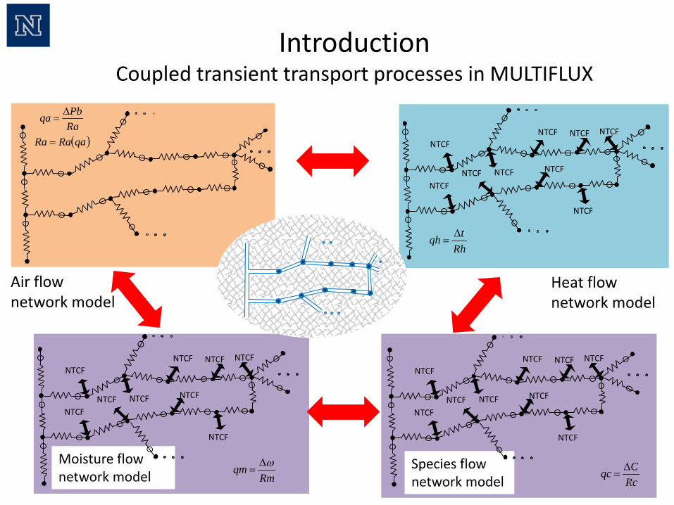
Introduction Coupled transient transport processes
Air flow network model
Heat flow network model
Moisture flow network model
Rhtqh ∆
=
Rmqm ω∆
=
RaPbqa ∆
=
( )qaRaRa = NTCF
NTCF NTCF NTCF
NTCF
NTCF
NTCF NTCF
NTCF
NTCF
NTCF NTCF NTCF
NTCF
NTCF
NTCF NTCF
NTCF
Species flow network model
NTCF
NTCF NTCF NTCF
NTCF
NTCF
NTCF NTCF
NTCF
RcCqc ∆
=6
Introduction Coupled transient transport processes in MULTIFLUX
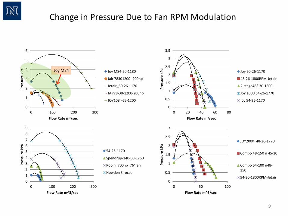
• Twin Joy M84 booster fans are modulated at 1450 level – Variable frequency modeled @ 50%
Real Mine Example Change in Airflow Directions due to Fan RPM Modulation
7
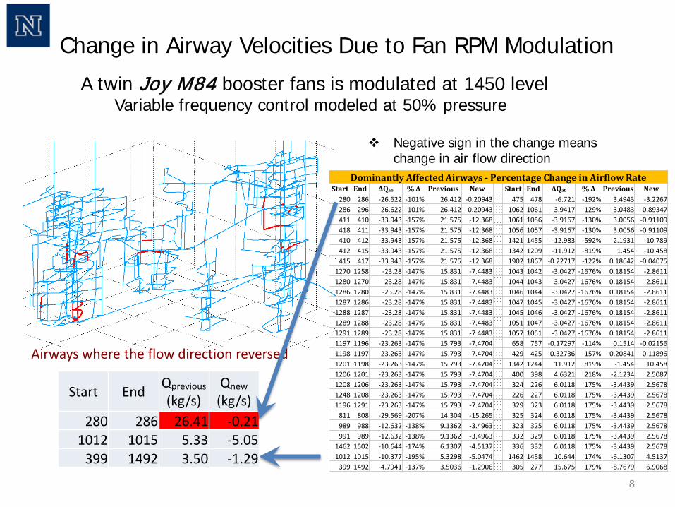
Change in Airway Velocities Due to Fan RPM Modulation
A twin Joy M84 booster fans is modulated at 1450 level Variable frequency control modeled at 50% pressure
Airways where the flow direction reversed
8
Dominantly Affected Airways - Percentage Change in Airflow Rate Start End ΔQab % Δ Previous New Start End ΔQab % Δ Previous New
drift pressure: Pb-1000 Padrift pressure: Pb+1000 Pa
0
10
20
30
0
10
20
30-6
-4
-2
0
2
4
6
x 10-9
0 500 1000 1500 2000 2500 3000 3500 40000
0.2
0.4
0.6
0.8
1
1.2
1.4
1.6
1.8
2x 10
-5
Time (sec)
Gas
Lib
erat
ion
Rat
e (k
g/s-
m2 )
NUFTNTCF
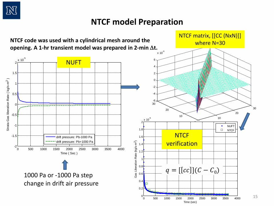
1000 Pa or -1000 Pa step change in drift air pressure
NUFT
NTCF verification
15
NTCF code was used with a cylindrical mesh around the opening. A 1-hr transient model was prepared in 2-min ∆t.
NTCF matrix, [[CC (NxN)]] where N=30
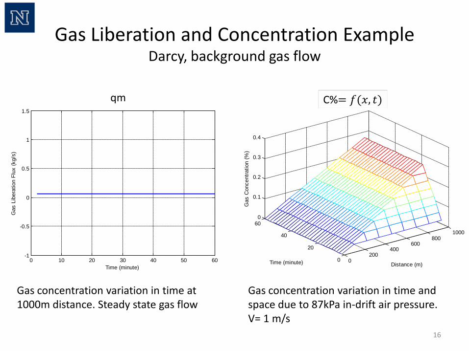
Gas Liberation and Concentration Example Darcy, background gas flow
16
0 10 20 30 40 50 60-1
-0.5
0
0.5
1
1.5
Time (minute)
Gas
Lib
erat
ion
Flux
(kg/
s)
0200
400600
8001000
0
20
40
600
0.1
0.2
0.3
0.4
Distance (m)Time (minute)
Gas
Con
cent
ratio
n (%
)
Gas concentration variation in time at 1000m distance. Steady state gas flow
Gas concentration variation in time and space due to 87kPa in-drift air pressure. V= 1 m/s
qm
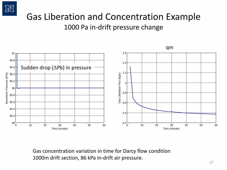
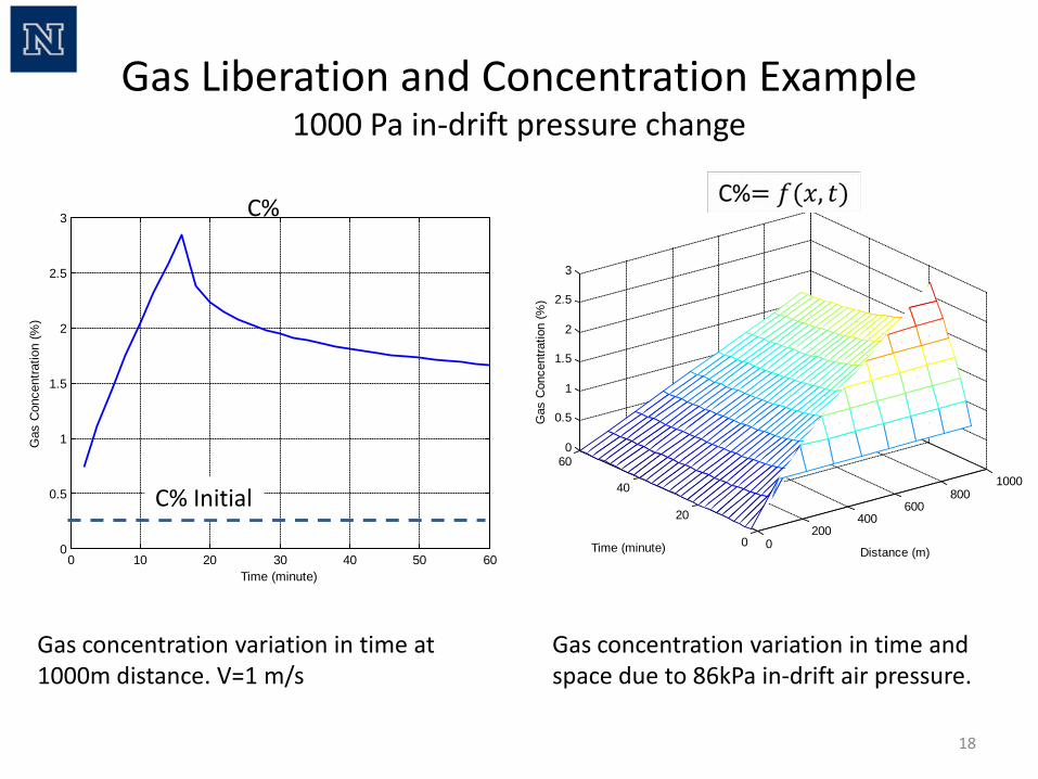
Gas Liberation and Concentration Example 1000 Pa in-drift pressure change
17
Gas concentration variation in time for Darcy flow condition 1000m drift section, 86 kPa in-drift air pressure.
0 10 20 30 40 50 600.2
0.4
0.6
0.8
1
1.2
1.4
1.6
Time (minute)
Gas
Lib
erat
ion
Flux
(kg/
s)
0 10 20 30 40 50 6085
85.2
85.4
85.6
85.8
86
86.2
86.4
86.6
86.8
87
Time (minute)
Bar
omet
ric P
ress
ure
(kP
a)
Sudden drop (∆Pb) in pressure
qm
18
0200
400600
8001000
0
20
40
600
0.5
1
1.5
2
2.5
3
Distance (m)Time (minute)G
as C
once
ntra
tion
(%)
Gas concentration variation in time at 1000m distance. V=1 m/s
Gas concentration variation in time and space due to 86kPa in-drift air pressure.
Gas Liberation and Concentration Example 1000 Pa in-drift pressure change
C%
0 10 20 30 40 50 600
0.5
1
1.5
2
2.5
3
Time (minute)
Gas
Con
cent
ratio
n (%
)
C% Initial
19
0 10 20 30 40 50 6085.5
86
86.5
87
Time (minute)
Bar
omet
ric P
ress
ure
(kP
a)
0 10 20 30 40 50 60-0.2
0
0.2
0.4
0.6
0.8
1
1.2
Time (minute)
Gas
Lib
erat
ion
Flux
(kg/
s)
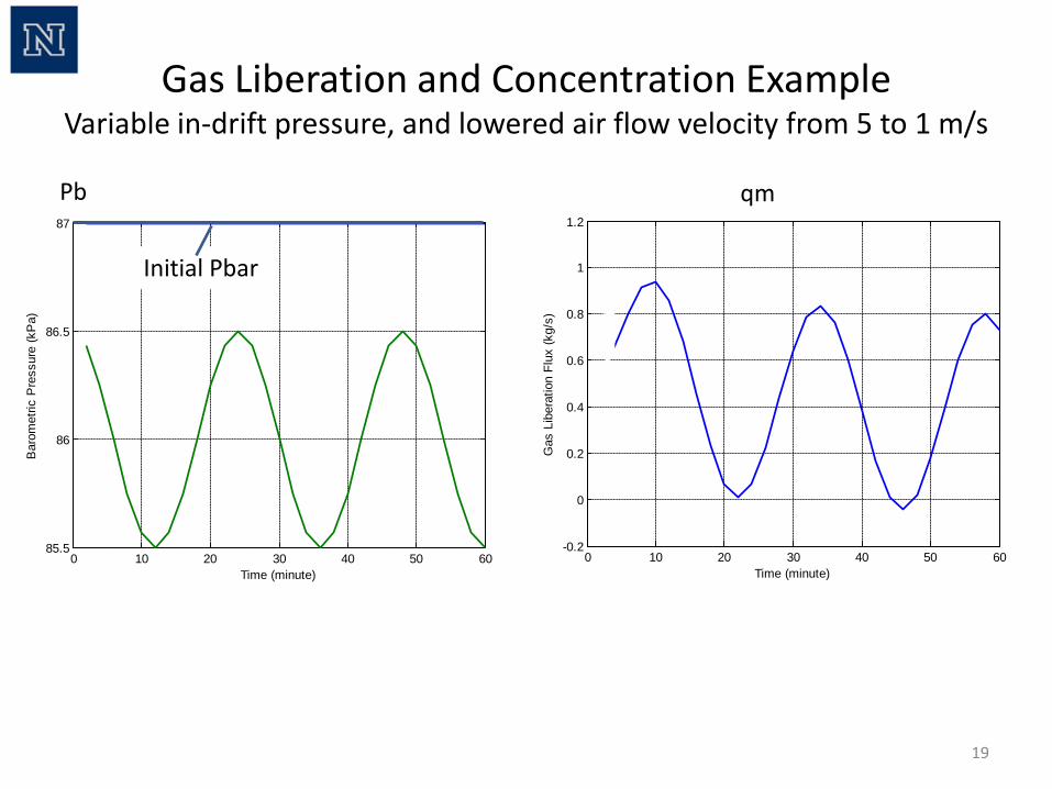
Gas Liberation and Concentration Example Variable in-drift pressure, and lowered air flow velocity from 5 to 1 m/s
Initial Pbar
qm Pb
20
0 10 20 30 40 50 600
0.5
1
1.5
2
2.5
3
3.5
Time (minute)
Gas
Con
cent
ratio
n (%
)
0
200
400
600
800
1000
010
2030
4050
60-1
0
1
2
3
4
Distance (m)Time (minute)
Gas
Con
cent
ratio
n (%
)
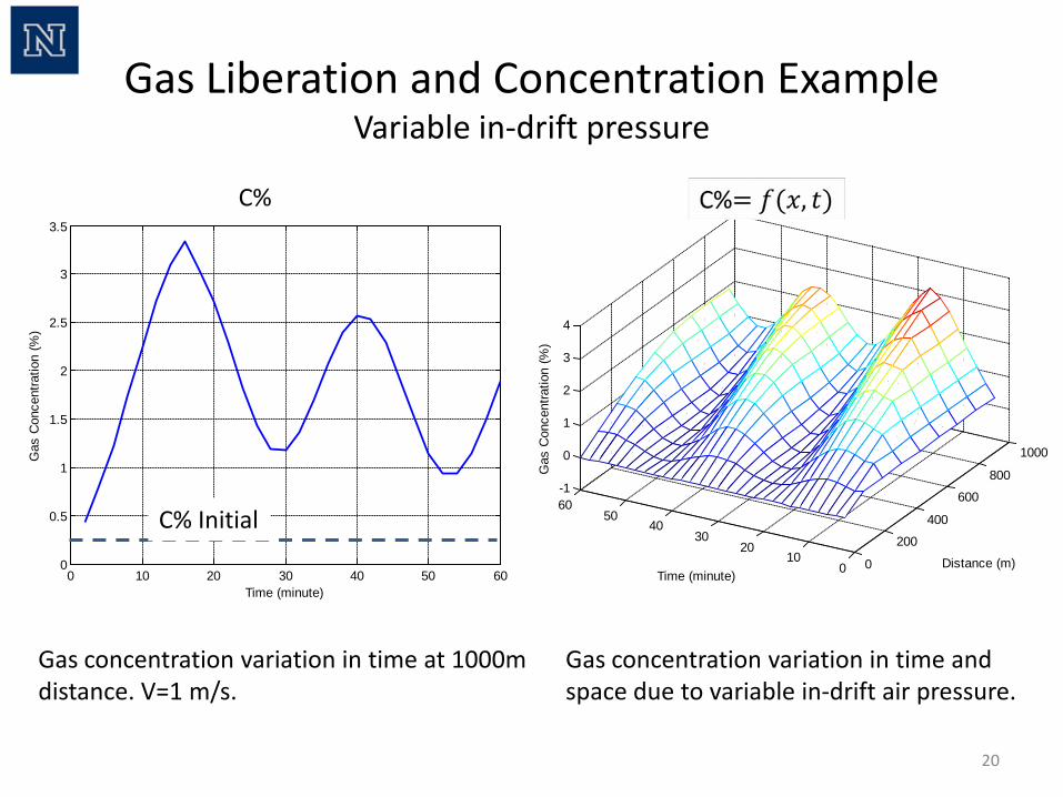
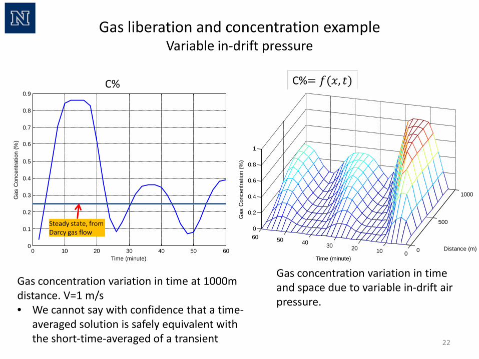
Gas concentration variation in time at 1000m distance. V=1 m/s.
Gas concentration variation in time and space due to variable in-drift air pressure.
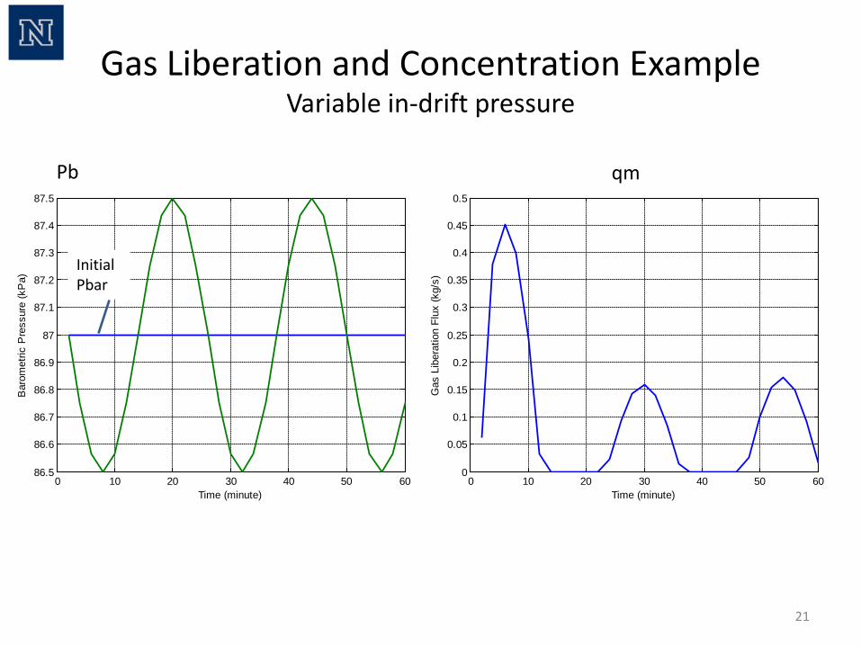
Gas Liberation and Concentration Example Variable in-drift pressure
C%
C% Initial
21
Gas Liberation and Concentration Example Variable in-drift pressure
0 10 20 30 40 50 6086.5
86.6
86.7
86.8
86.9
87
87.1
87.2
87.3
87.4
87.5
Time (minute)
Bar
omet
ric P
ress
ure
(kP
a)
0 10 20 30 40 50 600
0.05
0.1
0.15
0.2
0.25
0.3
0.35
0.4
0.45
0.5
Time (minute)
Gas
Lib
erat
ion
Flux
(kg/
s)
qm Pb
Initial Pbar
22
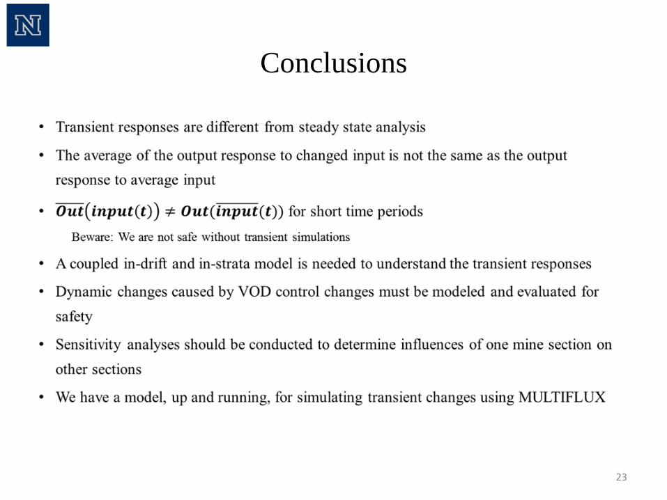
Gas concentration variation in time at 1000m distance. V=1 m/s • We cannot say with confidence that a time-
averaged solution is safely equivalent with the short-time-averaged of a transient
0 10 20 30 40 50 600
0.1
0.2
0.3
0.4
0.5
0.6
0.7
0.8
0.9
Time (minute)
Gas
Con
cent
ratio
n (%
)
0
500
1000
01020304050600
0.2
0.4
0.6
0.8
1
Distance (m)
Time (minute)
Gas
Con
cent
ratio
n (%
)
Gas concentration variation in time and space due to variable in-drift air pressure.
Steady state, from Darcy gas flow
Gas liberation and concentration example Variable in-drift pressure
C%
Conclusions
23
Acknowledgement
24
Thank You
Questions?
25
support
• 30 CFR § 77.201-2 Methane accumulations; change in ventilation. If, at any time, the air in any structure, enclosure or other facility contains 1.0 volume per centum or more of methane changes or adjustments in the ventilation of such installation shall be made at once so that the air shall contain less than 1.0 volume per centum of methane.
26
support • 30 CFR § 75.323
Actions for excessive methane. (a)Location of tests. Tests for methane concentrations under this section shall be made at least 12 inches from the roof, face, ribs, and floor. (b)Working places and intake air courses. (1) When 1.0 percent or more methane is present in a working place or an intake air course, including an air course in which a belt conveyor is located, or in an area where mechanized mining equipment is being installed or removed-- (i) Except intrinsically safe atmospheric monitoring systems (AMS), electrically powered equipment in the affected area shall be deenergized, and other mechanized equipment shall be shut off; (ii) Changes or adjustments shall be made at once to the ventilation system to reduce the concentration of methane to less than 1.0 percent; and (iii) No other work shall be permitted in the affected area until the methane concentration is less than 1.0 percent. (2) When 1.5 percent or more methane is present in a working place or an intake air course, including an air course in which a belt conveyor is located, or in an area where mechanized mining equipment is being installed or removed-- (i) Everyone except those persons referred to in §104(c) of the Act shall be withdrawn from the affected area; and (ii) Except for intrinsically safe AMS, electrically powered equipment in the affected area shall be disconnected at the power source. (c)Return air split. (1) When 1.0 percent or more methane is present in a return air split between the last working place on a working section and where that split of air meets another split of air, or the location at which the split is used to ventilate seals or worked-out areas changes or adjustments shall be made at once to the ventilation system to reduce the concentration of methane in the return air to less than 1.0 percent.
27
support • 30 CFR § 75.323
Actions for excessive methane. (2) When 1.5 percent or more methane is present in a return air split between the last working place on a working section and where that split of air meets another split of air, or the location where the split is used to ventilate seals or worked-out areas-- (i) Everyone except those persons referred to in §104(c) of the Act shall be withdrawn from the affected area; (ii) Other than intrinsically safe AMS, equipment in the affected area shall be deenergized, electric power shall be disconnected at the power source, and other mechanized equipment shall be shut off; and (iii) No other work shall be permitted in the affected area until the methane concentration in the return air is less than 1.0 percent.
• (d)Return air split alternative. (1) The provisions of this paragraph apply if-- (i) The quantity of air in the split ventilating the active workings is at least 27,000 cubic feet per minute in the last open crosscut or the quantity specified in the approved ventilation plan, whichever is greater; (ii) The methane content of the air in the split is continuously monitored during mining operations by an AMS that gives a visual and audible signal on the working section when the methane in the return air reaches 1.5 percent, and the methane content is monitored as specified in §75.351; and (iii) Rock dust is continuously applied with a mechanical duster to the return air course during coal production at a location in the air course immediately outby the most inby monitoring point. (2) When 1.5 percent or more methane is present in a return air split between a point in the return opposite the section loading point and where that split of air meets another split of air or where the split of air is used to ventilate seals or worked-out areas-- (i) Changes or adjustments shall be made at once to the ventilation system to reduce the concentration of methane in the return air below 1.5 percent; (ii) Everyone except those persons referred to in §104(c) of the Act shall be withdrawn from the affected area; (iii) Except for intrinsically safe AMS, equipment in the affected area shall be deenergized, electric power shall be disconnected at the power source, and other mechanized equipment shall be shut off; and (iv) No other work shall be permitted in the affected area until the methane concentration in the return air is less than 1.5 percent. (e)Bleeders and other return air courses. The concentration of methane in a bleeder split of air immediately before the air in the split joins another split of air, or in a return air course other than as described in paragraphs (c) and (d) of this section, shall not exceed 2.0 percent.