Abstract: 1. Introduction HSS has been used in a wide range of modern indus- trial applications by virtue of their small size to power ratios and its ability to apply very large force and torque. However, the dynamics of hydraulic systems are highly nonlinear [6]. Stamping stroke of a typical hydraulic mini press machine is traveling 200 mm stamping distance with high speed. Closed loop feedback control for HSS provides the ability to apply very large forces and tor- ques. The problems for HSS drives are their nonlinearities and low damping, and hence for some applications these systems are difficult for accurate control. The system conditions and parameters changes, depending on the operating conditions such as the mode of operation, which product is going to be made or what part of the process the machine is doing. Design of suitable control- ler to handle such type of situations is very important. The designed controller must operate properly to deal with nonlinear phenomenon and dynamics of the system parameters. The control signal errors are generally com- pared with velocity, position, force, pressure, and other system parameters. A HSS is a system consisting of mo- tor, servo, controller, power supply, and other system accessories. In HSS essentially, the system controls the cylinder position to track the velocity and acceleration trajectory values enforced by the operator. The cylinder movement must precisely follow position, speed, and acceleration profiles. In [9] have proposed a controller (not adaptive), which is compared with standard PD con- troller but applicable to industrial practice. In [2] propo- sed a hydraulic press control using spring back analysis. In this paper, which have presented a new PD control- ler for high-speed nonlinear hydraulic servo system. The The purpose of this paper is to present for modeling and simulation a hydraulic servo system (HSS). This work des- cribes the design and implementation of a control system for the operation of a hydraulic mini press machine. First, the system develops mathematical models for obtaining the system responses. While, the closed loop system is ba- sed on linearized model of feedback regulator of PD con- troller for high-speed control. The simulation experiment is performed using MATLAB and SIMULINK. An experimental set-up is constructed, which consists of microcontroller PIC 18F458 as controller. The simulation results, showing the effectiveness of the proposed approach. Keywords: modeling and simulation, hydraulic servo sys- tem, high speed hydraulic machine control. controller is demonstrated through its application in a hydraulic servo system and its performance is evaluated by comparison with other high-speed controller develo- ped by [3], [4], [5]. For industrial applications, which ne- ed algorithms that can adapt to nonlinear behavior trac- king position and velocity, which are fully matched by the processing speed of microcontroller. At the same time, PD controller is designed to verify the performance of the model, which is developed by simulation and com- pared to experimental results. The paper is organized as follows, In Section 2, a li- nearized mathematical model for the system is presen- ted. Section 3 presents the development and stability analysis of PD controller. Section 4 describes hardware system architectures. Simulations and experimental re- sults are presented in Section 5 and finally the paper is concluded The system describes detailed mathematical mode- ling of HSS for hydraulic mini press machine. The system consists of high-speed, electronic drives, hydraulic actu- ators, and position transducers. The mathematical model behavior of servo valves can be developed from the rela- tionship between the displacement ( ) and input vol- tage ( ) for the proportional valve. A third order model is sufficient for HSS, which is described by the equations given in following sections [11]. In pressing machine, the hydraulic actuator is typi- cally a double-acting hydraulic cylinder. The cylinder ports are connected to a proportional valve, and piston motion is obtained by modulating the oil flow into and out of the cylinder chambers. A servo valve provides this modulation as shown in Fig 1. The actuator can be pre- . 2. Mathematical Model x p m 2.1. System Modeling Fig. 1. A hydraulic actuator with four-way valve configu- ration. MODELING, SIMULATION AND CONTROL OF HIGH SPEED NONLINEAR HYDRAULIC SERVO SYSTEM Dechrit Maneetham, Nitin Afzulpurkar Received 29 ; accepted 3 . th August 2009 December 2009 rd Journal of Automation, Mobile Robotics & Intelligent Systems VOLUME 4, N° 1 2010 Articles 94
Transcript
Abstract:
1. IntroductionHSS has been used in a wide range of modern indus-
trial applications by virtue of their small size to powerratios and its ability to apply very large force and torque.However, the dynamics of hydraulic systems are highlynonlinear [6]. Stamping stroke of a typical hydraulic minipress machine is traveling 200 mm stamping distancewith high speed. Closed loop feedback control for HSSprovides the ability to apply very large forces and tor-ques. The problems for HSS drives are their nonlinearitiesand low damping, and hence for some applications thesesystems are difficult for accurate control. The systemconditions and parameters changes, depending on theoperating conditions such as the mode of operation,which product is going to be made or what part of theprocess the machine is doing. Design of suitable control-ler to handle such type of situations is very important.The designed controller must operate properly to dealwith nonlinear phenomenon and dynamics of the systemparameters. The control signal errors are generally com-pared with velocity, position, force, pressure, and othersystem parameters. A HSS is a system consisting of mo-tor, servo, controller, power supply, and other systemaccessories. In HSS essentially, the system controls thecylinder position to track the velocity and accelerationtrajectory values enforced by the operator. The cylindermovement must precisely follow position, speed, andacceleration profiles. In [9] have proposed a controller(not adaptive), which is compared with standard PD con-troller but applicable to industrial practice. In [2] propo-sed a hydraulic press control using spring back analysis.
In this paper, which have presented a new PD control-ler for high-speed nonlinear hydraulic servo system. The
The purpose of this paper is to present for modeling andsimulation a hydraulic servo system (HSS). This work des-cribes the design and implementation of a control systemfor the operation of a hydraulic mini press machine. First,the system develops mathematical models for obtainingthe system responses. While, the closed loop system is ba-sed on linearized model of feedback regulator of PD con-troller for high-speed control. The simulation experiment isperformed using MATLAB and SIMULINK. An experimentalset-up is constructed, which consists of microcontroller PIC18F458 as controller. The simulation results, showing theeffectiveness of the proposed approach.
Keywords: modeling and simulation, hydraulic servo sys-tem, high speed hydraulic machine control.
controller is demonstrated through its application ina hydraulic servo system and its performance is evaluatedby comparison with other high-speed controller develo-ped by [3], [4], [5]. For industrial applications, which ne-ed algorithms that can adapt to nonlinear behavior trac-king position and velocity, which are fully matched bythe processing speed of microcontroller. At the sametime, PD controller is designed to verify the performanceof the model, which is developed by simulation and com-pared to experimental results.
The paper is organized as follows, In Section 2, a li-nearized mathematical model for the system is presen-ted. Section 3 presents the development and stabilityanalysis of PD controller. Section 4 describes hardwaresystem architectures. Simulations and experimental re-sults are presented in Section 5 and finally the paper isconcluded
The system describes detailed mathematical mode-ling of HSS for hydraulic mini press machine. The systemconsists of high-speed, electronic drives, hydraulic actu-ators, and position transducers. The mathematical modelbehavior of servo valves can be developed from the rela-tionship between the displacement ( ) and input vol-tage ( ) for the proportional valve. A third order model issufficient for HSS, which is described by the equationsgiven in following sections [11].
In pressing machine, the hydraulic actuator is typi-cally a double-acting hydraulic cylinder. The cylinderports are connected to a proportional valve, and pistonmotion is obtained by modulating the oil flow into andout of the cylinder chambers. A servo valve provides thismodulation as shown in Fig 1. The actuator can be pre-
.
2. Mathematical Model
xp
�
2.1. System Modeling
Fig. 1. A hydraulic actuator with four-way valve configu-ration.
MODELING, SIMULATION AND CONTROL OF HIGH SPEED
NONLINEAR HYDRAULIC SERVO SYSTEM
Dechrit Maneetham, Nitin Afzulpurkar
Received 29 ; accepted 3 .th August 2009 December 2009rd
Journal of Automation, Mobile Robotics & Intelligent Systems VOLUME 4, N° 1 2010
Articles94
cisely controlled by regulating theflow rates and .However, the relationship between the piston position,
, and the flow rates depends on the dynamic propertiesof the load acting on the piston [1].
The mathematical model used in simulation is repre-sented by the following system of equations:
(1)
where
: effective bulk modulus
: actuator ram area
The objective for developing the actuator system dy-namics is to construct a strict - feedback control with fix-ed boundary layer to obtain precise position control ofa nonlinear electro-hydraulic servo system. The relationbetween the servo valve spool position and the inputvoltage can be considered as a second order system.
Substituting we obtain the valve velocity as
(3)
Where, is the transfer function, is the undampednatural frequency and is the damping ratio of the sys-tem. Defining the load pressure as andthe load flow as , the relationshipbetween the load pressure and the load flow for anideal critical servo valve with a matched and symmetricorifice can be expressed as follows:
(4)
The piston force equation is given by
The equation of motion of the load mass is ,where is the total mass of the load, andis the hydraulic force due to pressure differential acrossarea, we obtain
Defining the load pressure from equations (1) and(4).
Q Q
x
A
u
x
T s
= P P= Q + Q /
mx = F= AP
1 2
p
hyd
V
P
xCQ
x
x x
P PQ Q
P Q
m F
mx = F = AP
t
e
L
p
tp
L
v
e
L L
L L
L L
hyd L
hyd L
: total actuator volume
: load pressure
: actuator piston position: total coefficient of leakage: load flow
(2)
(5)
(6)
�
�
2.2. Hydraulic Actuator System Dynamics
v 5 5
1 2
1 2
2
2
=
( )
( ) 2
��
(7)
(8)
where :
Combining Eq. (1)-(5) with other system parameter,results in the system state equations given below:
(9)
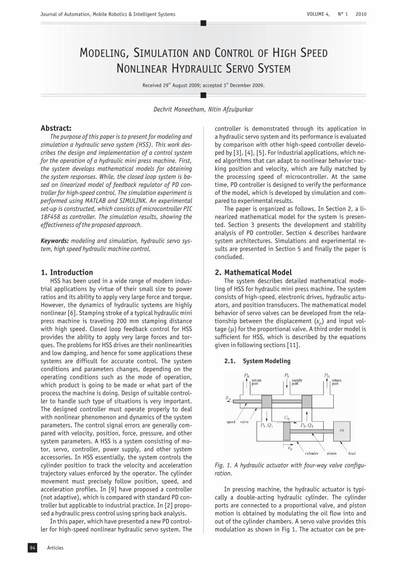
The data is separated into estimation data, which isused for identifying unknown system parameters andmeasurement data. Both factors are used for modeling inthe experiments. In order to excite all the relevant fre-quencies of the systems and to construct a good model,the frequencies are set for sinusoidal inputs with range of1 to 6 Hz and pressure of 5 Mpa. In conventional design ofa hydraulic servo system, third order transfer function isgenerally used, as given below
(10)
In frequency response analysis, which measure theamplitude of oscillations at the signal frequency. At first,which carried out a set of experiments using the openloop system to determine the amplitudes of oscillations,which occur at the signal frequency. In order to observethe signal frequency component of the response only,experiments are carried out using signal frequencies of 1,1.5, 2, 2.5, 3, 3.5, 4, 4.5, 5, 5.5 and 6 Hz at 5 Mpa pres-sure. Two different values of signal frequency are used inthe experimental determination of sine wave and stepresponse. Overall, the system identification is done byfitting a third order polynomial. The system transferfunction is found to be:
(11)
The correspondence levels between predicted modeland the experimental data for second order and the thirdorder models are about 74.16% and 80.77 %, respecti-vely. Fig. 2 shows a comparison between measured fre-quency responses.
:
:
2.3. Hydraulic Servo System ParameterIdentification
Journal of Automation, Mobile Robotics & Intelligent Systems VOLUME 4, N° 1 2010
P Ax C P QL tp L L��� � 4�e
Vt. .
x x x5 4 5���� � �� � �e e e2 2 22
T s( ) ������������x sv( ) �e
2
u s( ) s s2 2 �� �2 e e
x s x x sv e v e v e2 2 2���� � �� � �2
x s x s xv e v e v e2 2 2 �� � � � �2
x x xv e v e v e���� � �� � �2 2 22
.
.
.
.
.
...
..
.
Articles 95
result in terms of . The response is a set of the
velocity and its top most displacement range is
. Referring the equation (9)
where is gain. The line block is required for each
channel, where velocity is calculated. For that, area &force is added in to the block & friction is subtracted fromthe block.
The third method is load pressure system ( ). This isthe most effective method. The pressure of the system isset considering the pressure of the load. Pressure limit isthe supply pressure . The value of is deter-mined by substituting . To solve this equation, wemay assume a solution of the form
(12)
Overall, the main idea of the modified hydraulic sub-systems is to use valve position ( ), valve velocity ( )and input current ( ). The upper and lower limits inservo valve areequal to the stroke of the servo valve
and the maximum flow limitthrough the valve .
The results of an open loop test and correspondingsimulation model is presented for 1 Hz sin signal. Fromthe result the correlation between the control signalfrequency and error signal can be compared as follows:
±0.16
m/s
5MPa
: ± 2.38*10 m: 2.5*10 m /s
x
x
xx
x x
xQ
2
3
3
3
P : PP =
L L
L
v v
v
L
�
-4
-5 3
2.5. Simulation Result
.............................
2.4. Simulink ModelThe parameter variations used in simulations for in-
put, output, velocity, pressure, and flow rate. The systemparameters were varied so as to keep the damping coef-ficient ( ) constant. The values of the system and obser-ver parameters are given in Table 1.
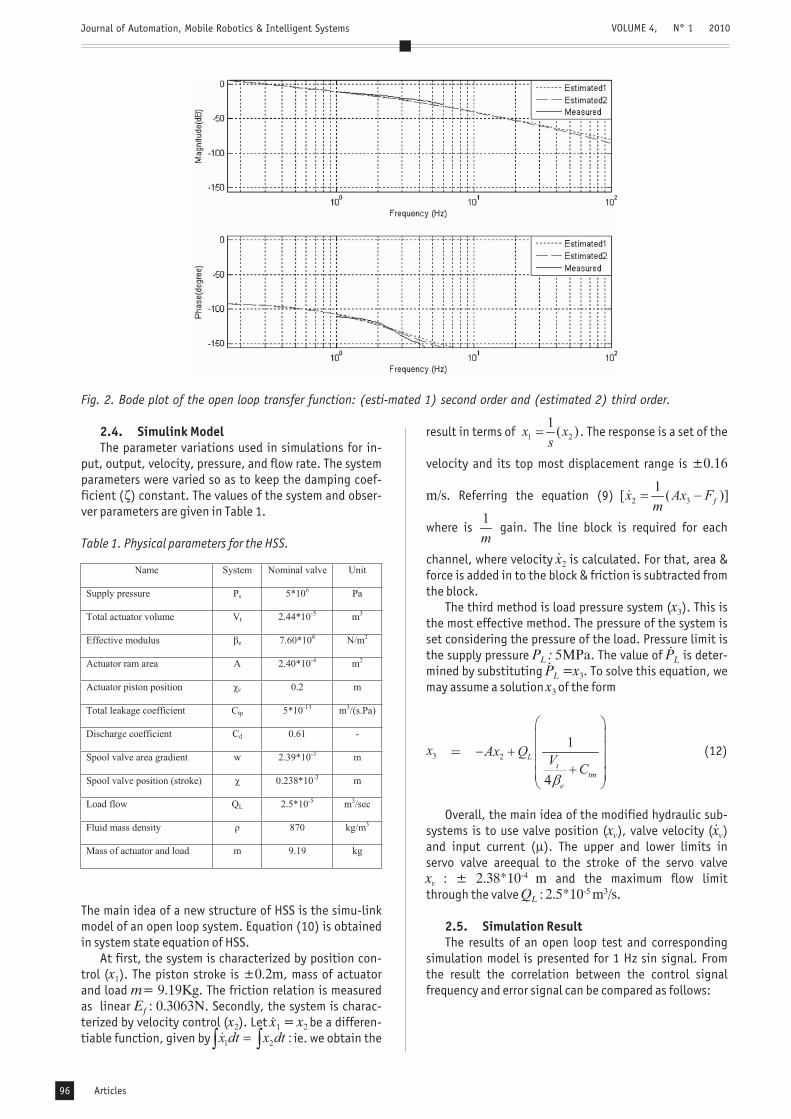
The main idea of a new structure of HSS is the simu-linkmodel of an open loop system. Equation (10) is obtainedin system state equation of HSS.
At first, the system is characterized by position con-trol ( ). The piston stroke is , mass of actuatorand load . The friction relation is measuredas linear . Secondly, the system is charac-terized by velocity control ( ). Let be a differen-tiable function, given by ie. we obtain the
�
Table 1. Physical parameters for the HSS.
x
Ex x x
1
2 1 2
±0.2m= 9.19Kg: 0.3063N
=
mf
Journal of Automation, Mobile Robotics & Intelligent Systems VOLUME 4, N° 1 2010
Fig. 2. Bode plot of the open loop transfer function: (esti-mated 1) second order and (estimated 2) third order.
.
.
.
..
Articles96
Journal of Automation, Mobile Robotics & Intelligent Systems VOLUME 4, N° 1 2010
Fig. 3. The simulink model of the open loop system.
Fig. 4. Experimental of the open loop system for 5 Mpaand 1 Hz sine wave.
Fig. 5. Simulink model of the open loop system for 5 Mpaand 1 Hz sine wave.
Fig. 6. Experimantal: velocity of the open loop systemfor 5 Mpa and 1 Hz sine wave.
Fig. 7. Simulink model: velocity of the open loop systemfor 5 Mpa and 1 Hz sine wave.
Fig. 8. Experimental: velocity of the open loop. Fig. 9. Simulink model: velocity of the open loop systemfor 5 Mpa and step response.
Articles 97
3. PD Control Design
4. Hardware System Architecture
The PD regulators for process control are the basis formany hydraulic control systems. Many variations in thebasic PD algorithm substantially improve its performanceand operability. A PD controller is parameterized by thefollowing transfer function.
(13)
This can be compared wit the following, general third-order characteristic equation.
(14)
Thus from equation (14), we obtain
(15)
The parameters of the PD controller are obtained asand . This controller is applied to
both the plant and model.
The HSS must follow the control theory guidelines,which is the main purpose to improve the velocity ofpiston in HSS. The hardware system of HSS is divided intotwo parts, which are explained below.
Firstly, which construct the mechanical model of anelectro-hydraulic system. The simulated response of themodel provides insight into the behavior of electro-hydraulic system.
K Kd d=10.46 = 0.074
4.1. Hardware Design
Fig. 10. Schematic diagram of the electro-hydraulic positioncontrol system.
As shown in Fig 10, (1) is the linear potentiometer; (2)is double cylinder; (3) is servo valve; (4) pressure reliefvalve represent fluid flows in out of the valve; (5) pressureunit is the input and output line pressures and (6) is themicrocontroller to control system.
The HSS consists of a hydraulic pump, servo valve,actuator, transducer, power supply, and microcontroller.Hydraulic system model is shown in Fig.11.
Journal of Automation, Mobile Robotics & Intelligent Systems VOLUME 4, N° 1 2010
Fig. 11. Electro-hydraulic servo system model.
Articles98
Journal of Automation, Mobile Robotics & Intelligent Systems
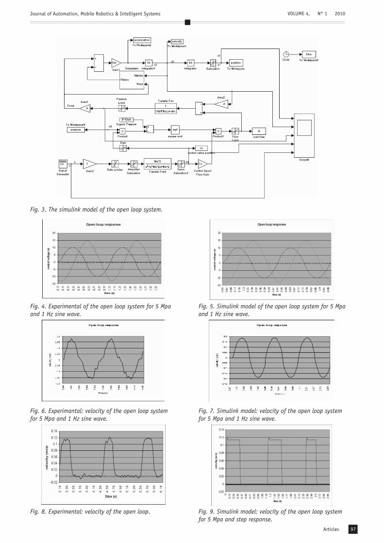
A microcontroller based control system has been deve-loped and used to control the hydraulic servo system. Weused microcontroller PIC 18F458 to control the hydraulicservo system, in conjunction with the data acquisitionprocessor. The schematic of microcontroller system de-sign is shown in Fig. 12. The mass flow rate across thefive-port valve is controlled by manipulating the spooloffset, by controlling the current supplied to the solenoid.
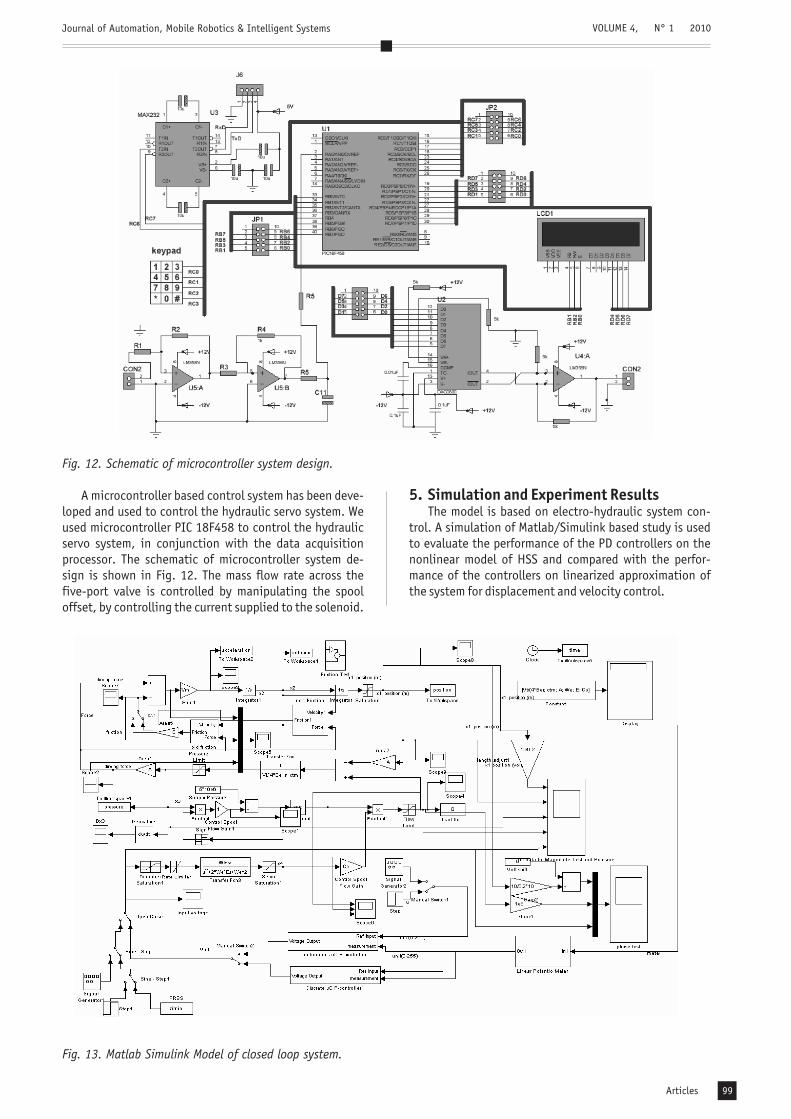
5. Simulation and Experiment ResultsThe model is based on electro-hydraulic system con-
trol. A simulation of Matlab/Simulink based study is usedto evaluate the performance of the PD controllers on thenonlinear model of HSS and compared with the perfor-mance of the controllers on linearized approximation ofthe system for displacement and velocity control.
VOLUME 4, N° 1 2010
Fig. 12. Schematic of microcontroller system design.
Fig. 13. Matlab Simulink Model of closed loop system.
Articles 99
Journal of Automation, Mobile Robotics & Intelligent Systems
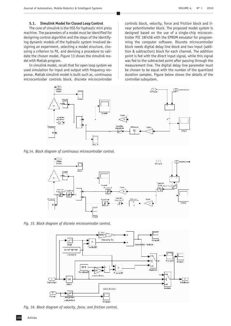
5.1. Simulink Model for Closed Loop ControlThe core of simulink is the HSS for hydraulic mini press
machine. The parameters of a model must be identified fordesigning control algorithm and the steps of the identify-ing dynamic models of the hydraulic system involved de-signing an experiment, selecting a model structure, cho-osing a criterion to fit, and devising a procedure to vali-date the chosen model. Figure 13 shows the simulink mo-del with Matlab program.
In simulink model, recall that for open loop system weused simulation for input and output with frequency res-ponse. Matlab simulink model is built such as, continuousmicrocontroller controls block, discrete microcontroller
controls block, velocity, force and friction block and li-near potentiometer block. The proposed model system isdesigned based on the use of a single-chip microcon-troller PIC 18F458 with the EPROM emulator for program-ming the computer software. Discrete microcontrollerblock needs digital delay line block and two input (addi-tion & subtraction) block for each channel. The additionpoint is fed with the direct input signal, while this signalwas fed to the subtracted point after passing through themeasurement line. The digital delay line parameter mustbe chosen to be equal with the number of the quantizedduration samples. Figure below shows the details of thecontroller subsystem.
VOLUME 4, N° 1 2010
Fig. 16. Block diagram of velocity, force, and friction control.
Fig. 15. Block diagram of discrete microcontroller control.
Fig.14. Block diagram of continuous microcontroller control.
Articles100
Journal of Automation, Mobile Robotics & Intelligent Systems
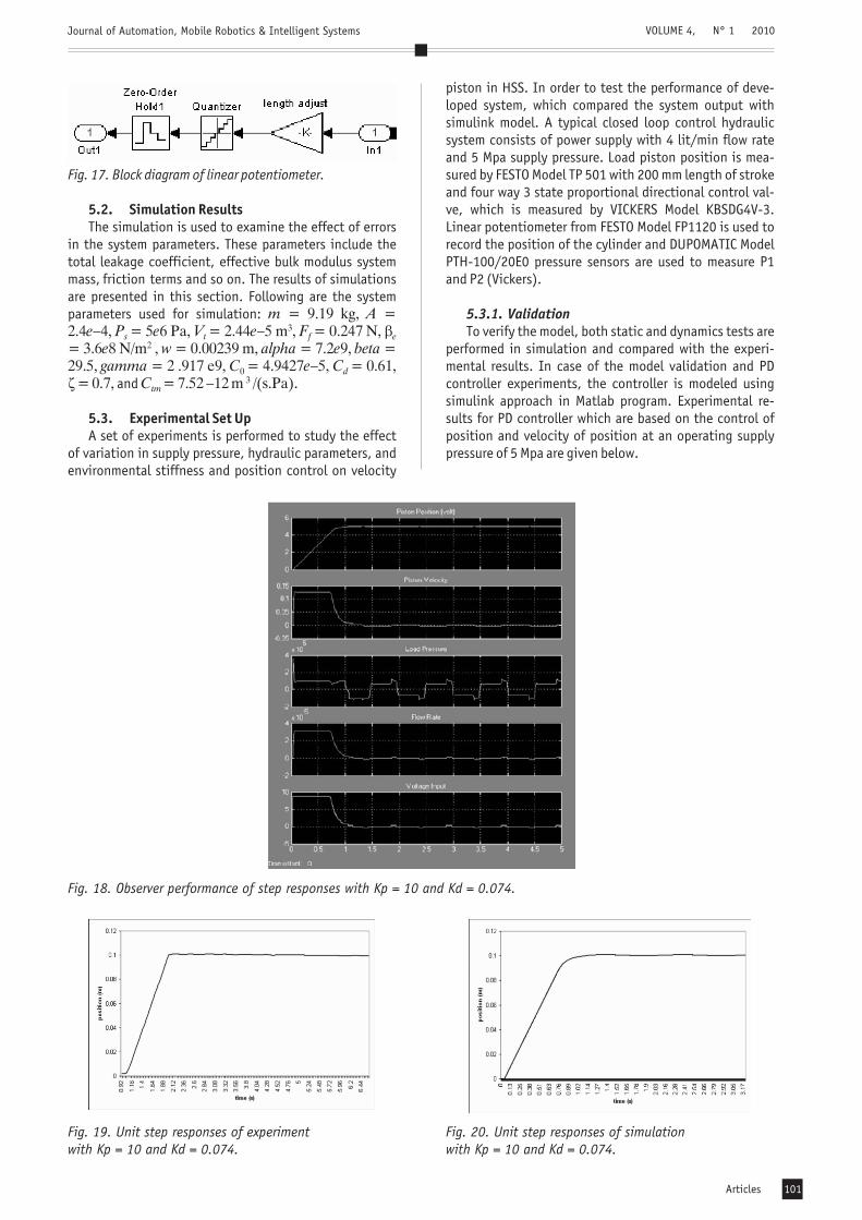
The simulation is used to examine the effect of errorsin the system parameters. These parameters include thetotal leakage coefficient, effective bulk modulus systemmass, friction terms and so on. The results of simulationsare presented in this section. Following are the systemparameters used for simulation:
and .
A set of experiments is performed to study the effectof variation in supply pressure, hydraulic parameters, andenvironmental stiffness and position control on velocity
piston in HSS. In order to test the performance of deve-loped system, which compared the system output withsimulink model. A typical closed loop control hydraulicsystem consists of power supply with 4 lit/min flow rateand 5 Mpa supply pressure. Load piston position is mea-sured by FESTO Model TP 501 with 200 mm length of strokeand four way 3 state proportional directional control val-ve, which is measured by VICKERS Model KBSDG4V-3.Linear potentiometer from FESTO Model FP1120 is used torecord the position of the cylinder and DUPOMATIC ModelPTH-100/20E0 pressure sensors are used to measure P1and P2 (Vickers).
To verify the model, both static and dynamics tests areperformed in simulation and compared with the experi-mental results. In case of the model validation and PDcontroller experiments, the controller is modeled usingsimulink approach in Matlab program. Experimental re-sults for PD controller which are based on the control ofposition and velocity of position at an operating supplypressure of 5 Mpa are given below.
5.3.1. Validation
VOLUME 4, N° 1 2010
Fig. 18. Observer performance of step responses with Kp = 10 and Kd = 0.074.
Fig. 19. Unit step responses of experimentwith Kp = 10 and Kd = 0.074.
Fig. 20. Unit step responses of simulationwith Kp = 10 and Kd = 0.074.
Articles 101
Journal of Automation, Mobile Robotics & Intelligent Systems
During the experimental test, only linear position ofthe movable cylinder is measured for feedback informa-tion. The velocity is obtained differentiating the posi-tion with respectto time at high speeds and pressure. Totest the effectiveness of the proposed controllers, we firstcompared it with a high-speed control system. The propo-sed control velocity is shown in Figure 22 with the gains
,and microcontroller control system. In [4], the controlresult of the proposed controller is shown in Figure 23,with corresponding feedback gains
and computer control system. In [8], the con-trol result of the proposed controller is shown in Figure24, with corresponding feedback gains
and computer control system. In [5],the control result of the proposed controller is shown inFigure 25, with corresponding feedback result
, overshooting is less than5% and computer control system. The control result of theproposed controller [3], with corresponding feedbackgains
and computer control system.The difference in the results shown in Figure 22 de-
monstrates that the proposed controller is much betterthan Figures 23, 24 and 25 in terms of high speed, tran-sient response and settling time. For the hydraulic minipress machine, the smaller the settling time is, the higherthe production rate will be. Therefore, it is significant forpractical applications. In addition, overshoot is muchsmaller. This is essential for hydraulic mini press machine,because a large overshoot will generate a large impactforce, which would damage the sheet metal forming.
The system has presented deviation, simulation, andimplementation of the nonlinear control law for HSS. Theproposed controller provides performance of the PD con-
s e t� 8 3
6. Conclusion
VOLUME 4, N° 1 2010
Fig. 21. Unit velocity responses experimentwith Kp = 10 and Kd = 0.074.
Fig. 22. Unit velocity responses simulationwith Kp = 10 and Kd = 0.074.
Fig. 23. Unit velocity responses simulation [4]. Fig. 24. Unit velocity responses simulation [8].
Fig. 25. Unit velocity responses simulation [5].
Articles102
Journal of Automation, Mobile Robotics & Intelligent Systems
troller for high-speed control. PD controller theory isintroduced as the control technique to accomplish thisgoal in this study, and the controllers designed using thismethod are validated using experimental tests. From the-se tests, it can be seen that, for hydraulic systems, whichhave nonlinear characteristics, control theory providesa powerful control strategy that clearly improves on PDcontrol in terms of high speed and transient response. Theresult shows the time constant of simulation and experi-ment, proportional-derivative controller with
.The comparison of the results between simulink and
hardware system for optimal PD controller indicates theimprovement of the simulation research, where the refe-rence velocity is and position is 39 mm. Thus,the response of the model gives a good control perfor-mance prediction of the PD controller.
- School of Engineering and Tech-nology, Asian Institute of Technology, Thailand. E-mail:[email protected].
- School of Engineering and Techno-logy Asian Institute of Technology, Thailand. Phone:+66(0)5245675, Fax: +66(0) 5245697. E-mail:[email protected].* Corresponding author
KpKd
= 10,= 0.074
0.125 m/s
ACKNOWLEDGMENTS
AUTHORSDechrit Maneetham*
Nitin Afzulpurkar
References
This support of this work by Ragamangala University of Techno-logy Thanyaburi (RMUTT) and by the Asian Institute of Techno-logy (AIT) is gratefully acknowledged.
[1] Alleyne A., Liu R., “Systematic control of a class ofnonlinear systems with application to electrohydrauliccylinder pressure control”,
, vol. 8, 2000, pp. 623-634.[2] Ferreira A.J., P. SunandJ. Gracio, “Close loop control of
a hydraulic press for springback analysis”,, 177, 2006, pp. 377-
381.[3] Fung F.R., Wang C.Y., Yang T.R., Huang H.H., “A vari-
able structure control with proportional and integralcompensations for electrohydraulic position servocontrol system”, , vol. 7, 1996, pp. 67-81.