54
Modeling System Structure and Dynamics with SysML Blocks Frontiers in Design & Simulation Research 2006 Georgia Institute of Technology March 16, 2006 Roger Burkhart Deere & Company
| Date post: | 25-Aug-2018 |
| Category: |
Documents |
| Upload: | nguyenquynh |
| View: | 216 times |
| Download: | 0 times |

Modeling System Structure andDynamics with SysML Blocks
Frontiers in Design & Simulation Research 2006Georgia Institute of Technology
March 16, 2006
Roger BurkhartDeere & Company

Modeling System Structure andDynamics with SysML Blocks
Frontiers in Design & Simulation Research 2006Georgia Institute of Technology
March 16, 2006
Roger BurkhartDeere & Company
Santa Fe Institute

Frontiers in Design & Simulation Research Mar. 16, 2006 - 3 -Modeling System Structure
Topics• Overview of SysML (UML for Systems
Engineering)- Background, objectives, and scope- Diagram types and examples- Status and prospects
• SysML Blocks as a foundation forknowledge management across the productdevelopment life cycle- Federated semantic models to cover an ever-
expanding scope of cross-domain and cross-process integration

Frontiers in Design & Simulation Research Mar. 16, 2006 - 4 -Modeling System Structure
UML for Systems Engineering• Joint initiative of International Council on
Systems Engineering (INCOSE) and OMGSystems Engineering special-interest group
• Provide computer-interpretable representation ofproducts throughout their development lifecycle- Facilitate communication/collaboration§ across engineering disciplines§ across development tasks and responsibilities
• Support systems engineering processes

Frontiers in Design & Simulation Research Mar. 16, 2006 - 5 -Modeling System Structure
Systems Engineering Processes• Requirements capture, allocation,
traceability• Conceptual design synthesis• Optimization and tradeoff analysis• Virtual validation and verification• Integration of specialized disciplines• Transition to downstream processes
- Detailed design definition- Manufacturing & lifetime support

Frontiers in Design & Simulation Research Mar. 16, 2006 - 6 -Modeling System Structure
Systems Engineering Lifecycle
Function
Subfunction
Design element
Subelement
FunctionalRequirement
NonfunctionalRequirement
Requirement derive
allocateTest &
Verification
satisfy satisfy verify
Communication, Coordination, Change Control
Frontiers in Design & Simulation Research Mar. 16, 2006 - 7 -Modeling System Structure
• Systems Engineers need a robust language foranalyzing, specifying, designing, verifying andvalidating systems
• Many different modeling techniques- Behavior diagrams, IDEF0, N2 charts, …
• General purpose language must:- satisfy broad set of modeling requirements (behavior,
structure, performance, … )- integrate with other disciplines (SW, HW, ..)- be scalable- be adaptable to different SE domains- be supported by multiple tools
SysML Motivation
Frontiers in Design & Simulation Research Mar. 16, 2006 - 8 -Modeling System Structure
• OMG Systems Engineering Activity chartered byInternational Council on Systems Engineering(INCOSE) and Object Management Group (OMG)in July 2001- create a semantic bridge between ISO 10303-233 standard and
ISO/IEC 19501 UML standard (UML 2 extensions in progress… )- create UML extended modeling language for specifying,
designing, and verifying complex systems using profiles, orother extensibility mechanisms.
- provide capability for rigorous transfer of specifications andrelated information among tools used by systems, software andhardware engineers
- bridge the semantic gap, the professional engineering disciplinegap, and the training gap that exists between systemsengineering and software engineering
INCOSE/OMG Joint Initiative
Frontiers in Design & Simulation Research Mar. 16, 2006 - 9 -Modeling System Structure
Current SysML Overview Slides
(See separate series of draft SysML Overviewslides being developed by SysML Merge Team.)
Frontiers in Design & Simulation Research Mar. 16, 2006 - 10 -Modeling System Structure
SysML Blocks• Built on UML 2 Composite Structure Diagrams originally
defined for specification of real-time software components• «block» stereotype provides a common root for user-
defined or domain-specific hierarchies of systemcomponent types- Hardware- Software- Data- Procedure- Facility- Person
• Blocks provide the backbone of the “system hierarchy”or“system of systems”architecture which drives the systemsengineering process
Frontiers in Design & Simulation Research Mar. 16, 2006 - 11 -Modeling System Structure
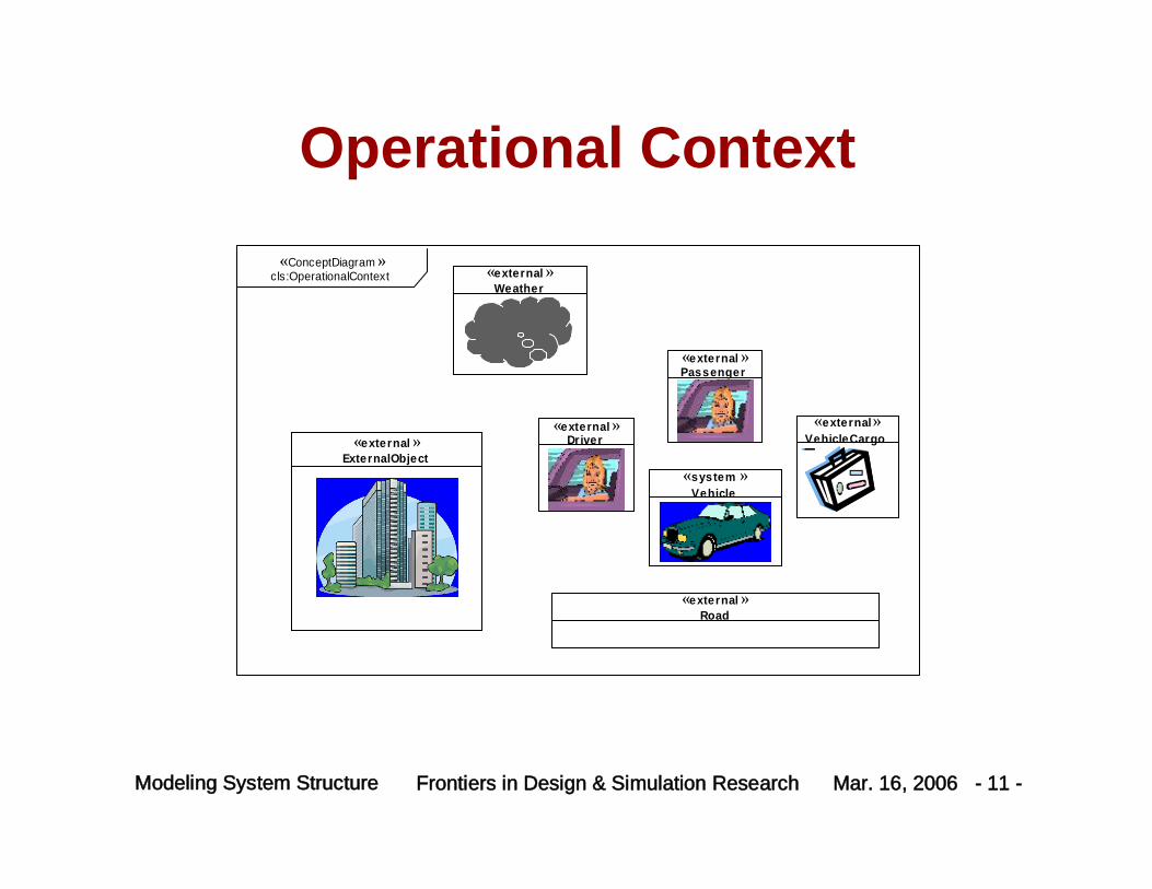
Operational Context
«system »Vehicle
«external »Driver
«ConceptDiagram »cls:OperationalContext «external »
Weather
«external »Road
«external »ExternalObject
«external »Passenger
«external»VehicleCargo

Frontiers in Design & Simulation Research Mar. 16, 2006 - 12 -Modeling System Structure
Product Structure Tree
«sys tem »Vehicle
«assembly»Pow er Train
«assem bly»Brake
«assembly»Steering
«assem bly»Body & Chassis
«assem bly»Engine
«assem bly»Transm iss ion
«assem bly»Transaxle
«assem bly»Whee l
«assem bly»V6-Engine
«assem bly»V8-Engine
{ or }
4
«deployment »«sof tw are » :vehicleControl
«assem bly»Vehicle Controller
«assem bly»Suspens ion
cls: VehicleSystemHierarchy
«diagramDescription»
version=”0.1"description=”vehicle assembly tree"reference=”Vehicle parts list”completeness=”partial”

Frontiers in Design & Simulation Research Mar. 16, 2006 - 13 -Modeling System Structure
Structure Modeling Foundation• Blocks are UML structured classes
- Classes extended with an ability to holdports, parts, and internal connectors
• “Block”captures a module at any level inthe system hierarchy.- Can represent external systems, a system
of interest, logical, physical, hardware,software, etc.
- Blocks provide both black-box view (withoutinternal structure) and white-box view(showing internal parts and connectors)
Frontiers in Design & Simulation Research Mar. 16, 2006 - 14 -Modeling System Structure
Parts, Ports, Connectors• Parts are properties that are enclosed by
assemblies and typed by classes- “Part”is defined as internal to assembly vs. ordinary
properties that reference other systems/objects
• Ports are parts that provide interaction points- notationally represented as a rectangle on the boundary
of a part (same as UML 2, but with option to show nameinside)
• Connectors bind one part to another- can connect parts with or without ports- typed by associations- structural features of the enclosing class
Frontiers in Design & Simulation Research Mar. 16, 2006 - 15 -Modeling System Structure
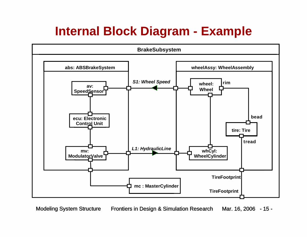
Internal Block Diagram - Example
wheelAssy: WheelAssemblyabs: ABSBrakeSystem
TireFootprint
mc : MasterCylinder
BrakeSubsystem
S1: Wheel Speed
L1: HydraulicLine
wheel:Wheel
whCyl:WheelCylinder
tire: Tire
av:SpeedSensor
ecu: ElectronicControl Unit
mv:ModulatorValve
rim
bead
tread
TireFootprint

Frontiers in Design & Simulation Research Mar. 16, 2006 - 16 -Modeling System Structure
White vs. Black Box Views
ABS Brake System
Master Cylinder In
ecu: ElectronicControl Unit
: Electronic
: Hydraulic
Brake LineOut
Wheel SpeedIn
av: Speed Sensor
mv:Modulator Valve
: Electronic
ABS Brake System
Master Cylinder In
Wheel SpeedIn
Brake LineOut
Frontiers in Design & Simulation Research Mar. 16, 2006 - 17 -Modeling System Structure
Concepts of Structure• SysML “Block”defines fundamental abstractions
of system structure- Individuals, whole-part relations, roles, connections- Reuse of standard components in larger whole
• Builds on UML class modeling foundation- Patterns and multiplicity of part occurrences- Built-in support for constraints and rules- Currently being mapped to Semantic Web and Common
Logic by OMG Ontology Definition Metamodel• Multiple models of system behavior can be built
and expressed on blocks foundation- Functional flow, finite-state, procedural,
continuous dynamics, discrete-event, ...
Frontiers in Design & Simulation Research Mar. 16, 2006 - 18 -Modeling System Structure
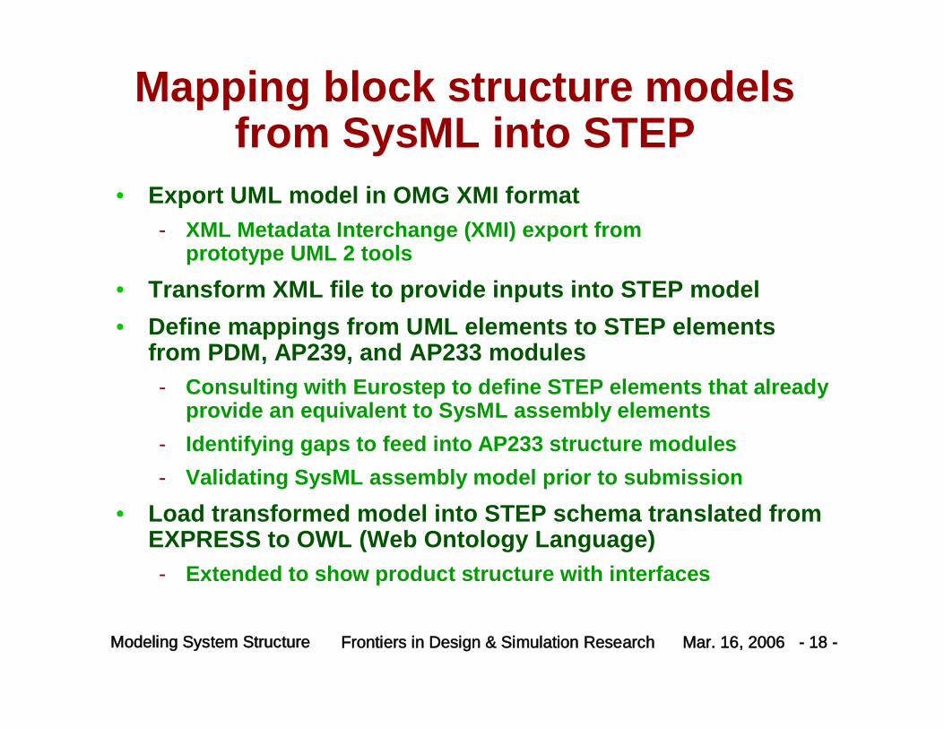
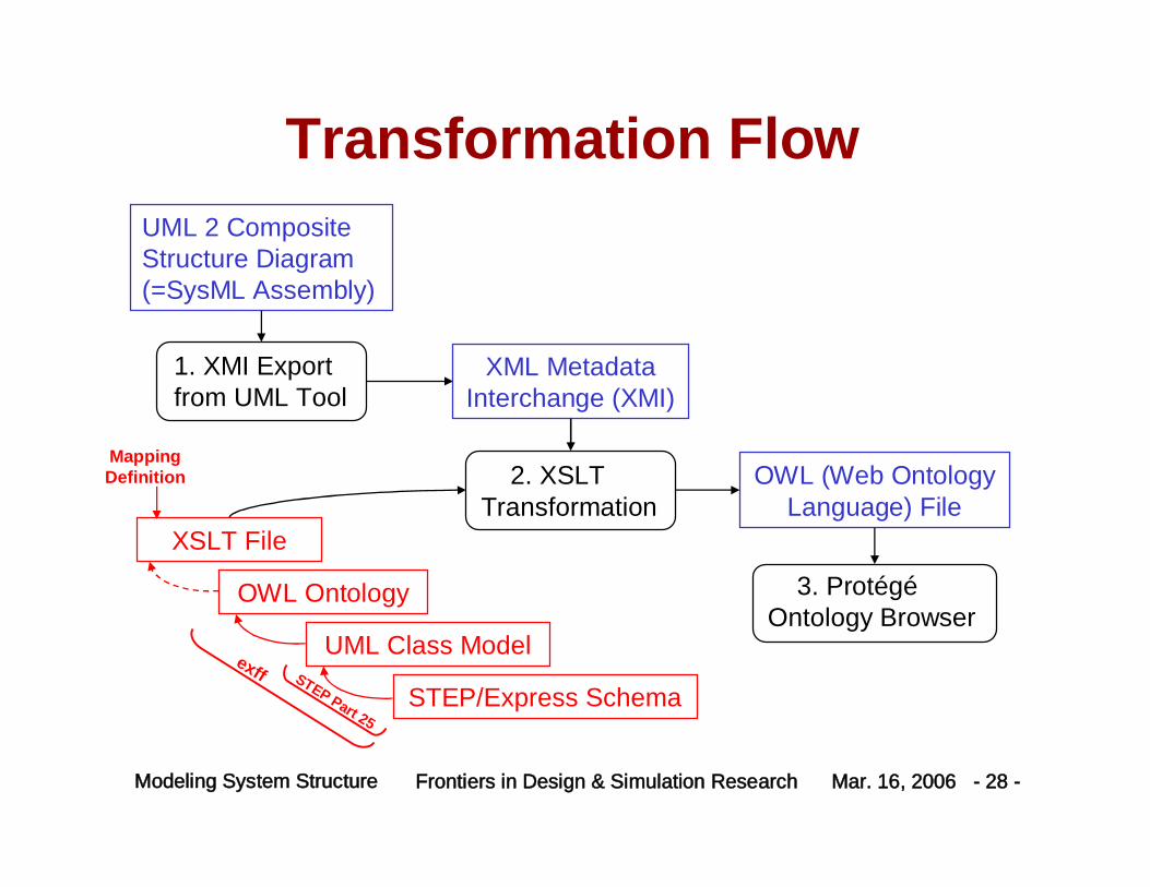
Mapping block structure modelsfrom SysML into STEP
• Export UML model in OMG XMI format- XML Metadata Interchange (XMI) export from
prototype UML 2 tools• Transform XML file to provide inputs into STEP model• Define mappings from UML elements to STEP elements
from PDM, AP239, and AP233 modules- Consulting with Eurostep to define STEP elements that already
provide an equivalent to SysML assembly elements- Identifying gaps to feed into AP233 structure modules- Validating SysML assembly model prior to submission
• Load transformed model into STEP schema translated fromEXPRESS to OWL (Web Ontology Language)- Extended to show product structure with interfaces

Frontiers in Design & Simulation Research Mar. 16, 2006 - 19 -Modeling System Structure
Selected Class of Application• Engineering block diagram models with hybrid
continuous/discrete behavior- Widely used with commercial tools across many
engineering disciplines- Examples can highlight added expressibility of SysML§ Structural variation§ Specialization/generalization§ …
- Includes full detail for simulation/execution§ Tangible verification with completeness check§ Export to many other tools and mathematical solvers
Frontiers in Design & Simulation Research Mar. 16, 2006 - 20 -Modeling System Structure
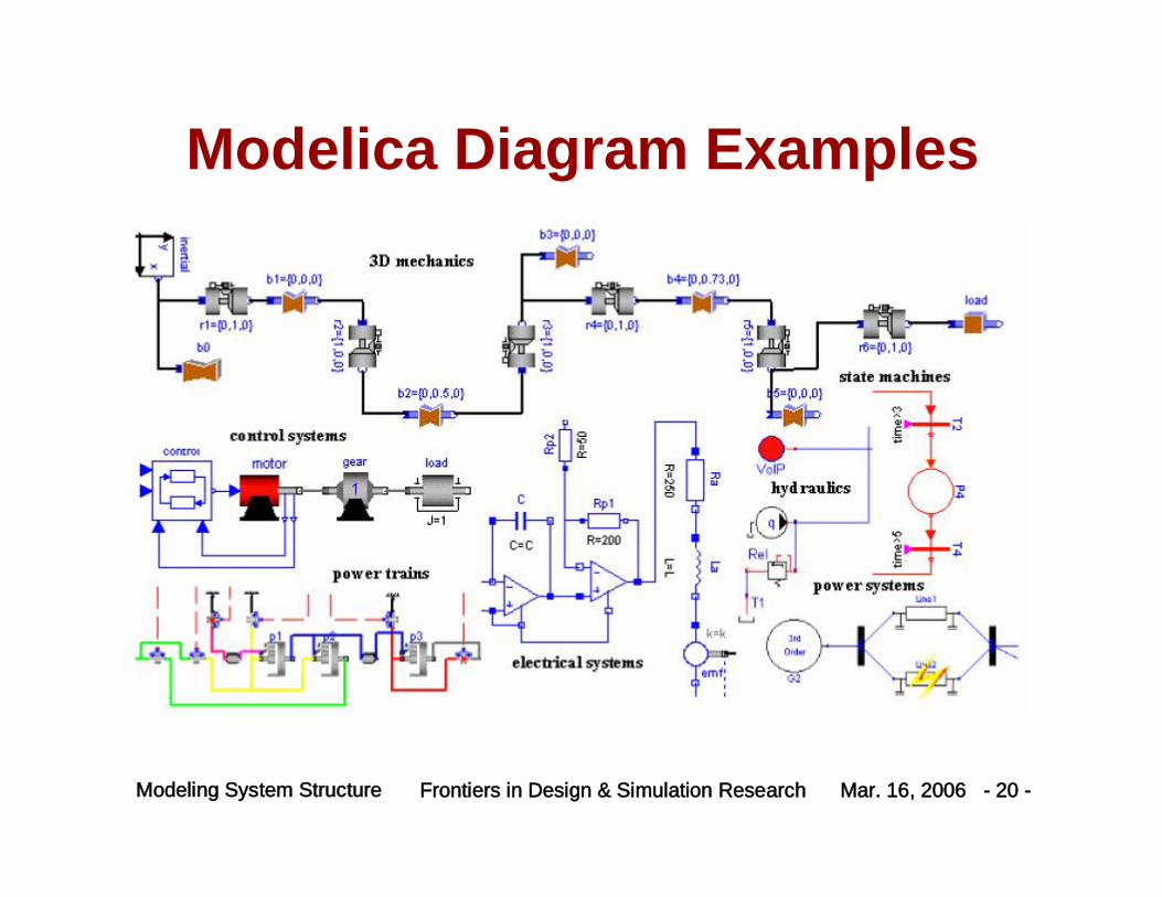
Modelica Diagram Examples

Frontiers in Design & Simulation Research Mar. 16, 2006 - 21 -Modeling System Structure
Modelica Languagemodel circuitResistor R1(R=10);Capacitor C(C=0.01);Resistor R2(R=100);Inductor L(L=0.1);Vsource AC AC;Ground G;
equationconnect (AC.p, R1.p); // Capacitorconnect (R1.n, C.p);connect (C.n, AC.n);connect (R1.p, R2.p); // Inductorconnect (R2.n, L.p);connect (L.n, C.n);connect (AC.n, G.p); // Ground
end circuit;
Frontiers in Design & Simulation Research Mar. 16, 2006 - 22 -Modeling System Structure
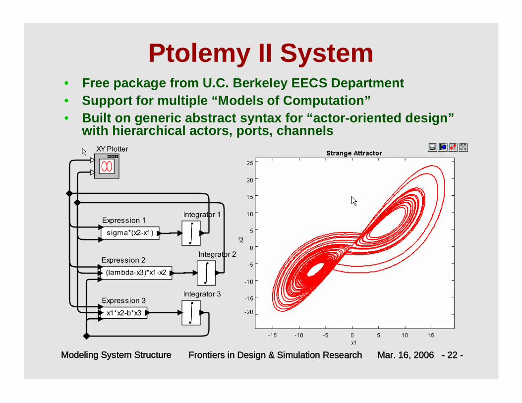
Ptolemy II System• Free package from U.C. Berkeley EECS Department• Support for multiple “Models of Computation”• Built on generic abstract syntax for “actor-oriented design”
with hierarchical actors, ports, channels
Frontiers in Design & Simulation Research Mar. 16, 2006 - 23 -Modeling System Structure
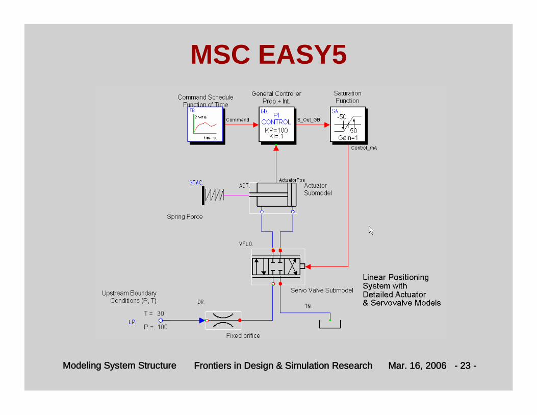
MSC EASY5
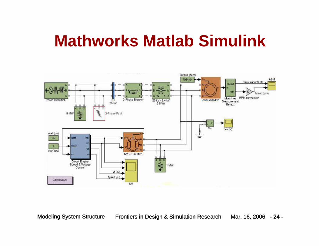
Frontiers in Design & Simulation Research Mar. 16, 2006 - 24 -Modeling System Structure
Mathworks Matlab Simulink

Frontiers in Design & Simulation Research Mar. 16, 2006 - 25 -Modeling System Structure
SysML Test Example
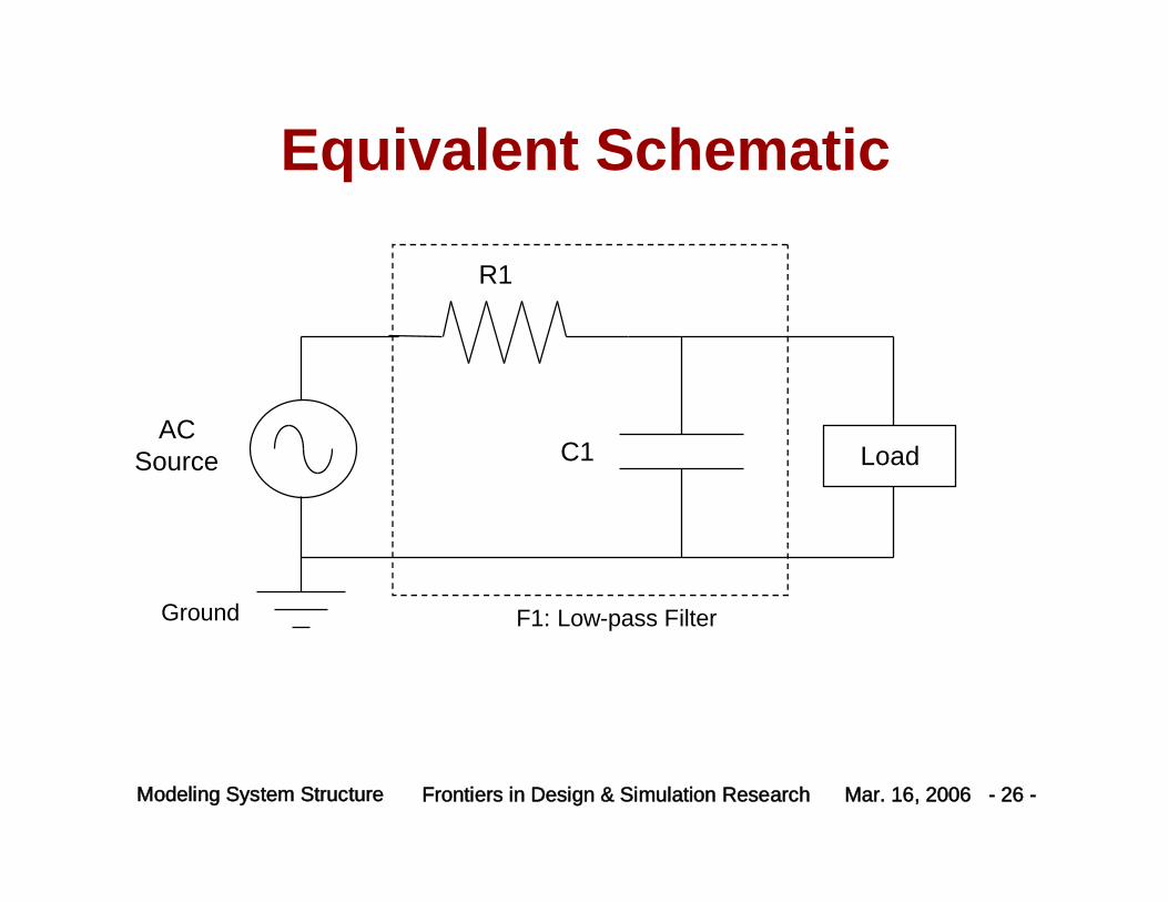
Frontiers in Design & Simulation Research Mar. 16, 2006 - 26 -Modeling System Structure
Equivalent Schematic
LoadC1
R1
ACSource
F1: Low-pass FilterGround

Frontiers in Design & Simulation Research Mar. 16, 2006 - 27 -Modeling System Structure
SysML Test Example
Part
Port
Part Definitions
Mid-level Block
Connector
Frontiers in Design & Simulation Research Mar. 16, 2006 - 28 -Modeling System Structure
Transformation FlowUML 2 CompositeStructure Diagram(=SysML Assembly)
1. XMI Exportfrom UML Tool
XML MetadataInterchange (XMI)
2. XSLTTransformation
OWL (Web OntologyLanguage) File
3. ProtégéOntology Browser
STEP/Express Schema
OWL Ontology
exffUML Class Model
STEP Part 25
XSLT File
MappingDefinition
Frontiers in Design & Simulation Research Mar. 16, 2006 - 29 -Modeling System Structure
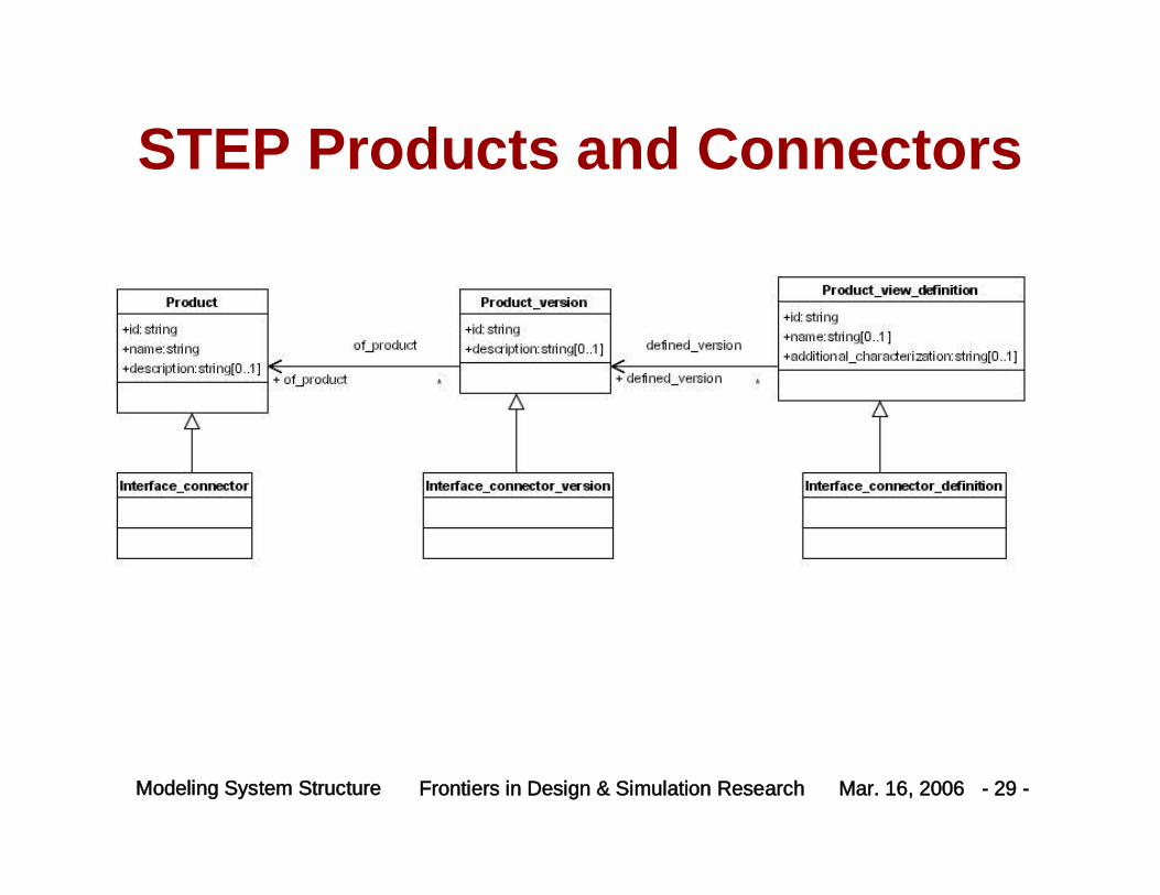
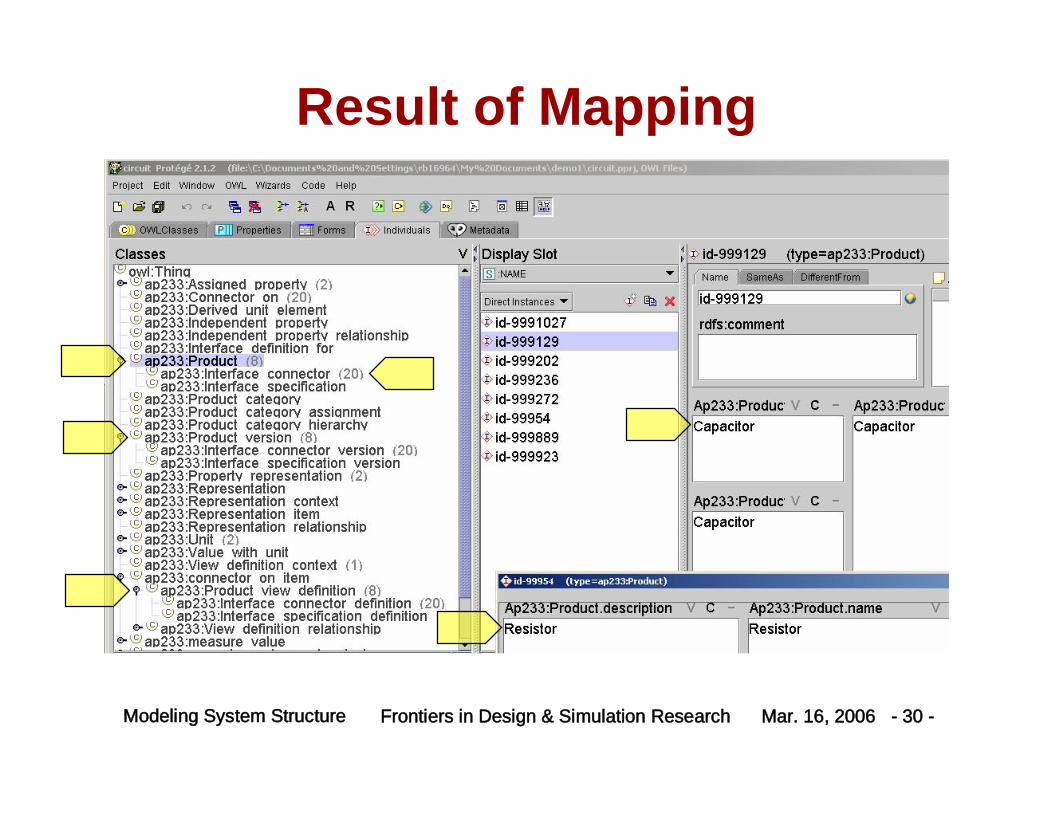
STEP Products and Connectors
Frontiers in Design & Simulation Research Mar. 16, 2006 - 30 -Modeling System Structure
Result of Mapping

Frontiers in Design & Simulation Research Mar. 16, 2006 - 31 -Modeling System Structure
Neutral Modeling Infrastructure
STEP/Express
UML/SysML OWL
Shared
Semantic
Models
Frontiers in Design & Simulation Research Mar. 16, 2006 - 32 -Modeling System Structure
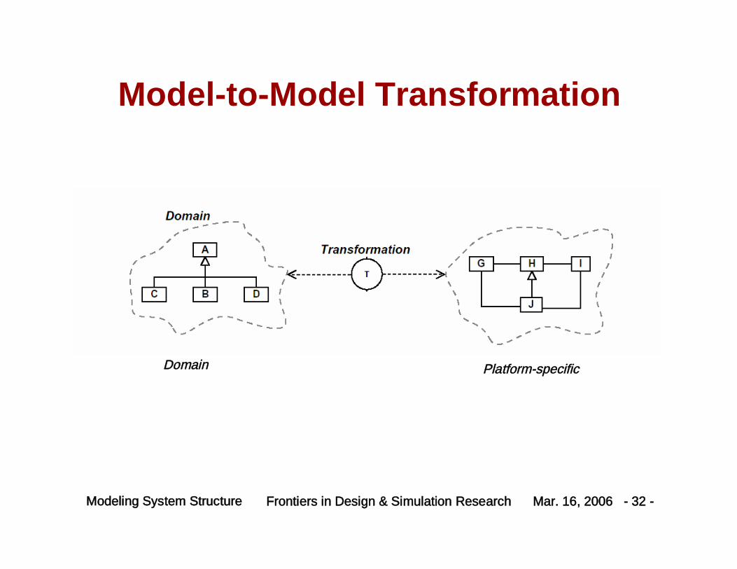
Model-to-Model Transformation
Domain Platform-specific

HAL System Structure DiagramSRL
Frontiers in Design & Simulation Research Mar. 16, 2006 - 34 -Modeling System Structure
Modeling Continuous Dynamics in SysML
• UML/SysML lacks any native representation forequations of continuous dynamics
• Georgia Tech “Reference Model”approachlinks system-level models in SysML to librarycomponents that carry internal equations
• SysML blocks can also provide a complete nativerepresentation of the equations themselves, withor without causality
• SysML can provide a neutral representation fortranslation between tools, to allow migration anddomain-specific choices for solvers, modeleditors, design and analysis tools

Frontiers in Design & Simulation Research Mar. 16, 2006 - 35 -Modeling System Structure
Further Work with Structure Models
• Multi-agent simulation of complexadaptive systems
• Constraint definition and constraint-basedprogramming
• A form of mereology as a starting point forcore ontology

System structure models for agents• “Systems thinking”is a hallmark of both complex adaptive
systems and “system of systems”engineering• Properties and functions at emergent levels is a persistent,
common theme- Many new engineering applications are increasingly recognized
as complex adaptive systems- Optimization criteria force attention to global vs. local levels
• Binding of components into system roles is a fundamentalabstraction for a “chemistry of composition”by which largerscale systems (including multi-level agents) are built- Goal of multi-agent simulation- Architecture for large-scale reuse- Agent life-cycle model for building the structure of an agent (and
its behavior) over its lifetime
Agent 2004 Oct. 7, 2004 - 50 -Standardizing an Agent Life-cycle Model
Frontiers in Design & Simulation Research Mar. 16, 2006 - 37 -Modeling System Structure
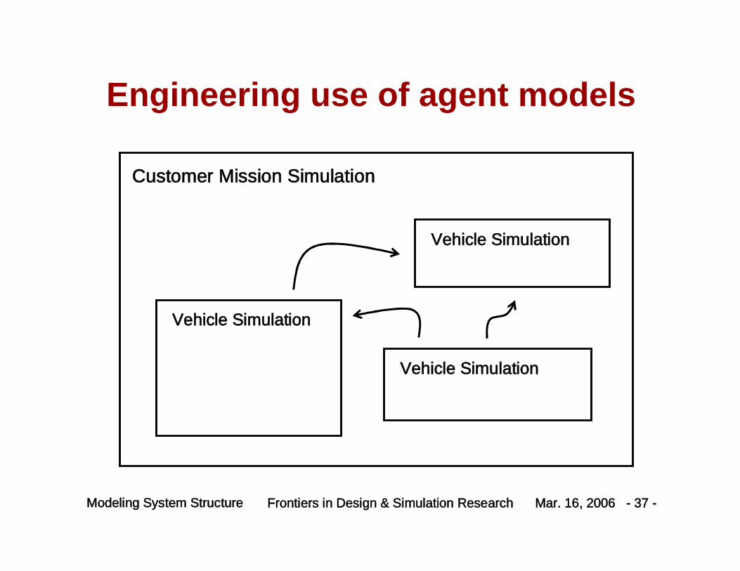
Engineering use of agent models
Customer Mission Simulation
Vehicle Simulation
Vehicle Simulation
Vehicle Simulation

Frontiers in Design & Simulation Research Mar. 16, 2006 - 38 -Modeling System Structure
Multi-level Systems Engineering• Simulation-based design and optimization
of working elements based on fieldscenarios
• Analysis for robustness, efficiency,adaptability, reusability, …
• Hierarchically nested based on level ofinterest- External customer processes- Products and missions- Design & internal operations
• Multiple scales in time & space
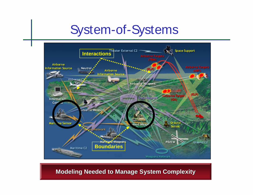
System-of-Systems
Boundaries
Interactions
Modeling Needed to Manage System ComplexityModeling Needed to Manage System Complexity
Frontiers in Design & Simulation Research Mar. 16, 2006 - 40 -Modeling System Structure
Swarm design goals• Conceptual framework for agent models
• Programming support for building agentsimulations
• Experimenter support for running simulations
• Nucleus for a community of agent modelers
Santa Fe Institute
Frontiers in Design & Simulation Research Mar. 16, 2006 - 41 -Modeling System Structure
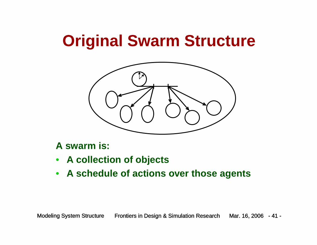
Original Swarm Structure
A swarm is:• A collection of objects• A schedule of actions over those agents

Frontiers in Design & Simulation Research Mar. 16, 2006 - 42 -Modeling System Structure
Hierarchical and Reflective Swarms

Frontiers in Design & Simulation Research Mar. 16, 2006 - 43 -Modeling System Structure
Swarm conceptual framework• Agents as objects• Agent behavior driven by schedules against
objects (discrete-event actions)• Composing behavior by mixing and merging
multiple schedules with randomization and partialorders
• Swarms (collections of objects and activity) toexpress emergent levels
Frontiers in Design & Simulation Research Mar. 16, 2006 - 44 -Modeling System Structure
Swarm Demo

Frontiers in Design & Simulation Research Mar. 16, 2006 - 45 -Modeling System Structure
Extension for agent life cyclesA swarm is:• A collection of objects• A schedule of actions over those agents• A schema that controls the development
and behavior of the swarm over its entirelifetime

Frontiers in Design & Simulation Research Mar. 16, 2006 - 46 -Modeling System Structure
Self-constructing swarms• Starting from an initial, minimal structure and
internal schema, let the swarm itself control thecreation of all internal structure and the behaviorit enables
• Similar to a process of biological development• Initial schema serves as an internal “genetic
code”that enables agents to share blueprints forcomponent construction and binding, includingtransfers across independent lifetimes
• Behavior model to express cognition, learning,organization, growth and evolution

Frontiers in Design & Simulation Research Mar. 16, 2006 - 47 -Modeling System Structure
Further Work with Structure Models
• Multi-agent simulation of complexadaptive systems
• Constraint definition and constraint-basedprogramming
• A form of mereology as a starting point fora top-level ontology

Frontiers in Design & Simulation Research Mar. 16, 2006 - 48 -Modeling System Structure
SysML constraint example
par: Firing Range
C.force: Force
S: Shot density:
acceleration:
volume:
«paramConstraint»R2: MassRelation
d:
v:
m:
«paramConstraint»R1: Newton's Law
f:
a:
m:

Frontiers in Design & Simulation Research Mar. 16, 2006 - 49 -Modeling System Structure
Functional programming example
Standard tutorial example, in Oz syntax
declarefun {Fact N}if N==0 then 1 else N*{Fact N-1} end
end

Frontiers in Design & Simulation Research Mar. 16, 2006 - 50 -Modeling System Structure
Black-box view of function
Factorial
N: Integer Result: Integer

Frontiers in Design & Simulation Research Mar. 16, 2006 - 51 -Modeling System Structure
White-box view of functionFactorial
s1: Compare
c1: Integer = 0
N: Integer Result: IntegerB
A
s2: If
s1: 0..1
Add
c1: = -1
Factorial
c1: Integer = 10..1
TestTF

Frontiers in Design & Simulation Research Mar. 16, 2006 - 52 -Modeling System Structure
Further Work with Structure Models
• Multi-agent simulation of complexadaptive systems
• Constraint definition and constraint-basedprogramming
• A form of mereology as a starting point fora top-level ontology
Frontiers in Design & Simulation Research Mar. 16, 2006 - 53 -Modeling System Structure
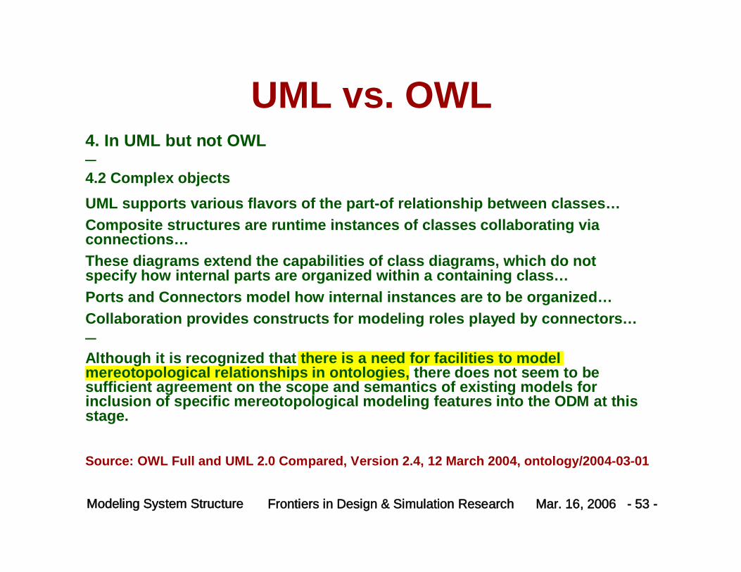
UML vs. OWL4. In UML but not OWL
4.2 Complex objectsUML supports various flavors of the part-of relationship between classes…Composite structures are runtime instances of classes collaborating viaconnections…These diagrams extend the capabilities of class diagrams, which do notspecify how internal parts are organized within a containing class…Ports and Connectors model how internal instances are to be organized…Collaboration provides constructs for modeling roles played by connectors…
Although it is recognized that there is a need for facilities to modelmereotopological relationships in ontologies, there does not seem to besufficient agreement on the scope and semantics of existing models forinclusion of specific mereotopological modeling features into the ODM at thisstage.
Source: OWL Full and UML 2.0 Compared, Version 2.4, 12 March 2004, ontology/2004-03-01

Frontiers in Design & Simulation Research Mar. 16, 2006 - 54 -Modeling System Structure
Further Work with Structure Models• Multi-agent simulation of complex
adaptive systems• Constraint definition and constraint-based
programming• A form of mereology as a starting point for
a top-level ontology
• General-purpose representationfor design structure models(static or dynamic, with or withoutsimulation)


