26


MODELING THEEFFECT OF DAMAGEIN COMPOSITESTRUCTURES

Aerospace Series ListModeling the Effect of Damage in Composite Structures: Simplified
ApproachesKassapoglou March 2015
Introduction to Aircraft Aeroelasticity and Loads, 2nd Edition Wright and Cooper December 2014
Aircraft Aerodynamic Design: Geometry and Optimization Sóbester and Forrester October 2014
Theoretical and Computational Aerodynamics Sengupta September 2014
Aerospace Propulsion Lee October 2013
Aircraft Flight Dynamics and Control Durham August 2013
Civil Avionics Systems, 2nd Edition Moir, Seabridge and Jukes August 2013
Modelling and Managing Airport Performance Zografos, Andreatta andOdoni
July 2013
Advanced Aircraft Design: Conceptual Design, Analysis andOptimization of Subsonic Civil Airplanes
Torenbeek June 2013
Design and Analysis of Composite Structures: With Applications toAerospace Structures, 2nd Edition
Kassapoglou April 2013
Aircraft Systems Integration of Air-Launched Weapons Rigby April 2013
Design and Development of Aircraft Systems, 2nd Edition Moir and Seabridge November 2012
Understanding Aerodynamics: Arguing from the Real Physics McLean November 2012
Aircraft Design: A Systems Engineering Approach Sadraey October 2012
Introduction to UAV Systems 4e Fahlstrom and Gleason August 2012
Theory of Lift: Introductory Computational Aerodynamics withMATLAB and Octave
McBain August 2012
Sense and Avoid in UAS: Research and Applications Angelov April 2012
Morphing Aerospace Vehicles and Structures Valasek April 2012
Gas Turbine Propulsion Systems MacIsaac and Langton July 2011
Basic Helicopter Aerodynamics, 3rd Edition Seddon and Newman July 2011
Advanced Control of Aircraft, Spacecraft and Rockets Tewari July 2011
Cooperative Path Planning of Unmanned Aerial Vehicles Tsourdos et al November 2010
Principles of Flight for Pilots Swatton October 2010
Air Travel and Health: A Systems Perspective Seabridge et al September 2010
Design and Analysis of Composite Structures: With applications toaerospace Structures
Kassapoglou September 2010
Unmanned Aircraft Systems: UAVS Design, Development andDeployment
Austin April 2010
Introduction to Antenna Placement & Installations Macnamara April 2010
Principles of Flight Simulation Allerton October 2009
Aircraft Fuel Systems Langton et al May 2009
The Global Airline Industry Belobaba April 2009
Computational Modelling and Simulation of Aircraft and theEnvironment: Volume 1 - Platform Kinematics and SyntheticEnvironment
Diston April 2009
Handbook of Space Technology Ley, Wittmann Hallmann April 2009
Aircraft Performance Theory and Practice for Pilots Swatton August 2008
Aircraft Systems, 3rd Edition Moir & Seabridge March 2008
Introduction to Aircraft Aeroelasticity And Loads Wright & Cooper December 2007
Stability and Control of Aircraft Systems Langton September 2006
Military Avionics Systems Moir & Seabridge February 2006
Design and Development of Aircraft Systems Moir & Seabridge June 2004
Aircraft Loading and Structural Layout Howe May 2004
Aircraft Display Systems Jukes December 2003
Civil Avionics Systems Moir & Seabridge December 2002

MODELING THEEFFECT OF DAMAGEIN COMPOSITESTRUCTURESSIMPLIFIED APPROACHES
Christos Kassapoglou
Delft University of Technology, The Netherlands

This edition first published 2015© 2015 John Wiley & Sons Ltd
Registered officeJohn Wiley & Sons Ltd, The Atrium, Southern Gate, Chichester, West Sussex, PO19 8SQ, UnitedKingdom
For details of our global editorial offices, for customer services and for information about how to applyfor permission to reuse the copyright material in this book please see our website at www.wiley.com.
The right of the author to be identified as the author of this work has been asserted in accordance withthe Copyright, Designs and Patents Act 1988.
All rights reserved. No part of this publication may be reproduced, stored in a retrieval system, ortransmitted, in any form or by any means, electronic, mechanical, photocopying, recording orotherwise, except as permitted by the UK Copyright, Designs and Patents Act 1988, without the priorpermission of the publisher.
Wiley also publishes its books in a variety of electronic formats. Some content that appears in printmay not be available in electronic books.
Designations used by companies to distinguish their products are often claimed as trademarks. Allbrand names and product names used in this book are trade names, service marks, trademarks orregistered trademarks of their respective owners. The publisher is not associated with any product orvendor mentioned in this book.
Limit of Liability/Disclaimer of Warranty: While the publisher and author have used their best effortsin preparing this book, they make no representations or warranties with respect to the accuracy orcompleteness of the contents of this book and specifically disclaim any implied warranties ofmerchantability or fitness for a particular purpose. It is sold on the understanding that the publisher isnot engaged in rendering professional services and neither the publisher nor the author shall be liablefor damages arising herefrom. If professional advice or other expert assistance is required, the servicesof a competent professional should be sought
Library of Congress Cataloging-in-Publication Data
applied for.
A catalogue record for this book is available from the British Library.
ISBN: 9781119013211
Typeset in 11/13pt TimesLTStd by Laserwords Private Limited, Chennai, India
1 2015

Contents
Series Preface ixPreface xi
1 Damage in Composite Structures: Notch Sensitivity 11.1 Introduction 11.2 Notch Insensitivity 21.3 ‘Complete’ Notch Sensitivity 41.4 Notch Sensitivity of Composite Materials 5
Exercises 6References 7
2 Holes 92.1 Stresses around Holes 132.2 Using the Anisotropic Elasticity Solution to Predict Failure 162.3 The Role of the Damage Zone Created Near a Hole 172.4 Simplified Approaches to Predict Failure in Laminates with Holes: the
Whitney–Nuismer Criteria 192.5 Other Approaches to Predict Failure of a Laminate with a Hole 242.6 Improved Whitney–Nuismer Approach 252.7 Application: Finding the Stacking Sequence Which Results in Good
OHT Performance 34Exercises 35References 39
3 Cracks 413.1 Introduction 413.2 Modelling a Crack in a Composite Laminate 423.3 Finite-Width Effects 453.4 Other Approaches for Analysis of Cracks in Composites 463.5 Matrix Cracks 49
Exercises 52References 56
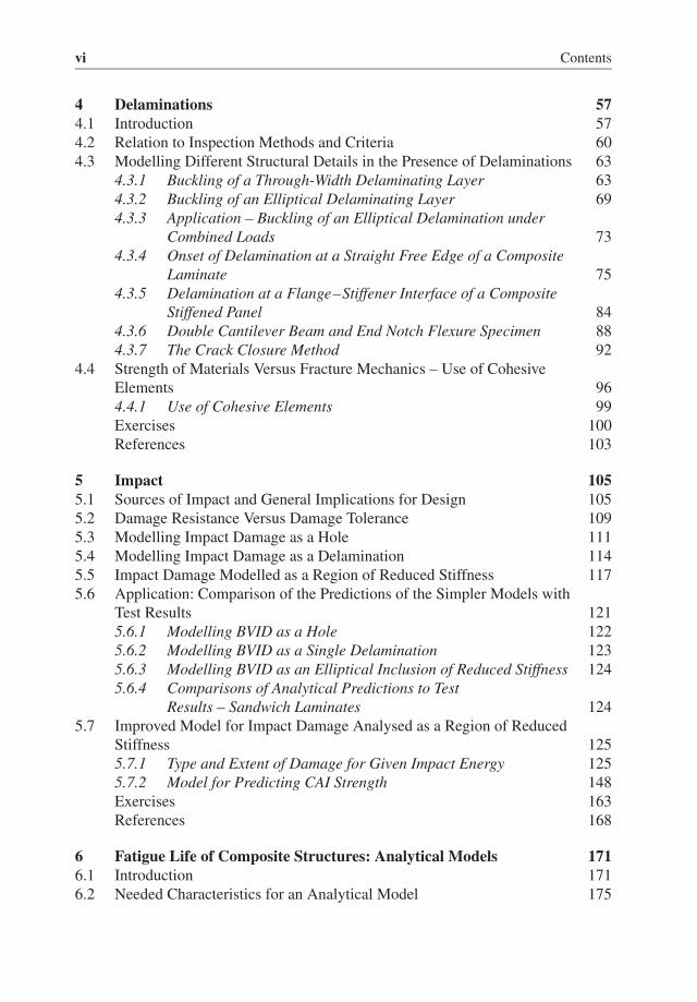
vi Contents
4 Delaminations 574.1 Introduction 574.2 Relation to Inspection Methods and Criteria 604.3 Modelling Different Structural Details in the Presence of Delaminations 63
4.3.1 Buckling of a Through-Width Delaminating Layer 634.3.2 Buckling of an Elliptical Delaminating Layer 694.3.3 Application – Buckling of an Elliptical Delamination under
Combined Loads 734.3.4 Onset of Delamination at a Straight Free Edge of a Composite
Laminate 754.3.5 Delamination at a Flange–Stiffener Interface of a Composite
Stiffened Panel 844.3.6 Double Cantilever Beam and End Notch Flexure Specimen 884.3.7 The Crack Closure Method 92
4.4 Strength of Materials Versus Fracture Mechanics – Use of CohesiveElements 964.4.1 Use of Cohesive Elements 99Exercises 100References 103
5 Impact 1055.1 Sources of Impact and General Implications for Design 1055.2 Damage Resistance Versus Damage Tolerance 1095.3 Modelling Impact Damage as a Hole 1115.4 Modelling Impact Damage as a Delamination 1145.5 Impact Damage Modelled as a Region of Reduced Stiffness 1175.6 Application: Comparison of the Predictions of the Simpler Models with
Test Results 1215.6.1 Modelling BVID as a Hole 1225.6.2 Modelling BVID as a Single Delamination 1235.6.3 Modelling BVID as an Elliptical Inclusion of Reduced Stiffness 1245.6.4 Comparisons of Analytical Predictions to Test
Results – Sandwich Laminates 1245.7 Improved Model for Impact Damage Analysed as a Region of Reduced
Stiffness 1255.7.1 Type and Extent of Damage for Given Impact Energy 1255.7.2 Model for Predicting CAI Strength 148Exercises 163References 168
6 Fatigue Life of Composite Structures: Analytical Models 1716.1 Introduction 1716.2 Needed Characteristics for an Analytical Model 175

Contents vii
6.3 Models for the Degradation of the Residual Strength 1776.3.1 Linear Model 1776.3.2 Nonlinear Model 180
6.4 Model for the Cycles to Failure 1836.4.1 Extension to Spectrum Loading 196
6.5 Residual Strength and Wear-Out Model Predictions Compared to TestResults 2006.5.1 Residual Strength Predictions Compared to Test Results 2006.5.2 Cycles to Failure Predictions Compared to Test Results
(Constant Amplitude) 2026.5.3 Cycles to Failure Predictions Compared to Test Results
(Spectrum Loading) 2046.6 A Proposal for the Complete Model: Accounting for Larger Scale
Damage 2066.6.1 First Cycle, Tension Portion 2076.6.2 First Cycle, Compression Portion 2076.6.3 Subsequent Load Cycles 2086.6.4 Discussion 2086.6.5 Application: Tension–Compression Fatigue of Unidirectional
Composites 2096.6.6 Application: Tension–Tension Fatigue of Cross-Ply Laminates 214Exercises 218References 219
7 Effect of Damage in Composite Structures: Summary and UsefulDesign Guidelines 221
Index 227


Series Preface
The field of aerospace is multi-disciplinary and wide ranging, covering a large varietyof products, disciplines and domains, not merely in engineering but in many relatedsupporting activities. These combine to enable the aerospace industry to produceexciting and technologically advanced vehicles. The wealth of knowledge and experi-ence that has been gained by expert practitioners in the various aerospace fields needsto be passed onto others working in the industry, including those just entering fromUniversity.The Aerospace Series aims to be a practical, topical and relevant series of books
aimed at people working in the aerospace industry, including engineering profession-als and operators, allied professions such commercial and legal executives, and alsoengineers in academia. The range of topics is intended to be wide ranging, coveringdesign and development, manufacture, operation and support of aircraft, as well astopics such as infrastructure operations and developments in research and technology.Composite materials are being used increasingly in aerospace structures due to
their impressive strength to weight properties, and the ability to manufacture complexintegral components. However, in structural design, it is also important to be able toaccount for the effect of damage on the structure’s integrity throughout its lifetime.This book, Modelling the Effect of Damage in Composite Structures: Simplified
Approaches, considers the various types of damage that can occur in composite struc-tures and how they can be modelled during preliminary structural design. Analyticalmodels are developed in order to understand and predict the physical phenomenathat lead to the onset of damage and its evolution. The techniques provide a set ofdesign tools and rules of thumb for a range of different types of damage in compositestructures. The book complements the author’s previous book Design and Analysisof Composite Structures: With Application to Aerospace Structures, Second Editionwhich is also in the Wiley Aerospace Series.
Peter Belobaba, Jonathan Cooper and Allan Seabridge


Preface
One of the main features of a good structural design is the ability to account for dam-age representative of what may occur during the lifetime of the structure and ensurethat performance is not compromised with such damage present. For the case of air-frame structures, knowledge of the effects of damage on structural performance iscrucial in designing safe but weight-efficient structures.This book provides a brief discussion of various types of damage and how they
can be modelled during preliminary design and analysis of composite structures. It isaddressed to graduate-level students and entry-level design and structural engineers.It is the result of a graduate course at Delft University of Technology covering designand analysis of composite structures in the presence of damage. While the emphasisis on aerospace structures, the principles and methods are applicable to all other fieldswith appropriate adjustment of safety factors and design criteria (e.g. impact damage).Because the emphasis is on preliminary design and analysis, more accurate, and
absolutely necessary during detailed design, computational methods such as finite ele-ments are only briefly touched upon during the discussion. As a result, the accuracyand applicability of some of the approaches presented are not as good as those result-ing from detailed finite element analysis. However, the methods are very efficient andprovide good starting designs for more detailed subsequent evaluation. They can alsobe used to compare different designs and thus can be very useful for optimisation.In a sense, this book is a natural continuation of my previous book on Design and
Analysis of Composite Structures. There, the effect of damage was conservativelyaccounted for by applying appropriate knockdown factors on the allowable strength.Here, an attempt is made to replace these knockdown factors with analytical modelsthat focus on understanding better some of the physical phenomena behind damagecreation and evolution, while, at the same time, removing some of the conservatismassociated with knockdown factors.It is also recognised that some of the subjects discussed in this book such as the
analysis of structures with impact damage or the fatigue analysis of composite struc-tures are very much the subject of on-going research. As such, the methods presentedhere should be viewed as good design tools that may be superseded in the future as ourunderstanding of damage creation and evolution in composite structures improves.

xii Preface
Chapter 1 includes a brief overview of types of damage and points out someimportant characteristics specific to composites manifested by increased notchsensitivity compared to metals. Chapter 2 discusses the effect of holes and providesimproved methodology to obtain reliable failure predictions. Chapter 3 discussesthrough-thickness cracks and gives simple methods of analysis to obtain failurepredictions. Delaminations are discussed in Chapter 4 where solutions for differentstructural details are given. Impact damage, which includes all previous typesof damage, matrix cracks, holes (for high impact energies) and delaminations, isaddressed in Chapter 5. A brief discussion of fatigue of composite materials with anemphasis on analytical models for predicting cycles to failure is given in Chapter 6.Constant amplitude and spectrum loading are discussed with an emphasis on howdamage at different length scales may be accounted for in the analysis. Finally,design guidelines and rules of thumb that can be deduced from all previous chaptersare summarised in Chapter 7.
Christos Kassapoglou

1Damage in CompositeStructures: Notch Sensitivity
1.1 Introduction
Owing to its construction, where two basic constituents, fibres and matrix, arecombined, a composite structure shows a wide variety of types of damage. Damagemay be specific to one or both of the constituents or involve interaction of the two.Furthermore, depending on the scale over which phenomena are described, damagemay have different forms ranging from micro-voids or inconsistencies and cracks ofthe fibre/matrix interphase to large-scale delaminations, holes and laminate failures.Here, the emphasis is placed on damage that is no smaller than a few fibre diameters
with the understanding that this damagemost likely is the result of creation and coales-cence of damage at smaller scales, which are beyond the scope of this book. Withinthis framework, the most common forms of damage are matrix cracks, fibre/matrixinterface failures, fibre failures, through-thickness failures (holes and cracks) andinter-ply failures such as delaminations. Of course any combination of these mayalso occur as in cases of impact damage. Representative forms of damage and theircorresponding scales are shown in Figure 1.1.In advanced composites typical of aerospace structures, the matrix has much lower
strength than the fibres. Failure then typically initiates in the matrix and the associateddamage is in the form of matrix cracks. These cracks usually appear in plies withfibres not aligned with the directions along which appreciable loads are applied [1].Matrix cracks may also be present in a composite right after curing due to curingstresses [2] or tooling problems where heat uptake or cool-down during the cure cycleis not uniform [3].This does not mean that damage may not initiate at a location where a small flaw
(resin-rich region, resin-poor region, void and contamination) is present. Ideally, adamage model should start at the lowest possible scale where damage initiated andtrack the latter as it evolves and grows. As can be seen from Figure 1.1, however, thisprocess may require bridging at least three to four orders of magnitude in the lengthscale. This means that separate models for the individual constituents are needed at the
Modeling the Effect of Damage in Composite Structures: Simplified Approaches, First Edition. Christos Kassapoglou.© 2015 John Wiley & Sons, Ltd. Published 2015 by John Wiley & Sons, Ltd.

2 Modeling the Effect of Damage in Composite Structures
Single fibre
Ply level:
−45/0/−45 plies
Matrix crack
transitioning to
delamination
Matrix
crack
Laminate level: 6 mm
thick impacted laminate
Delaminations
Panel level: 15 cm wide
sandwich panel with
wrinkling
(compression) failure)
Compression failure
of facesheet
Surface flaw
1.E-05 1.E-04 1.E-03 1.E-02 m
Figure 1.1 Typical damage at various scales of a composite structure
lower scales at which even the material homogeneity is in doubt. To minimise compu-tational complexity, models that address macroscopic structures start at larger scales,the ply level or, less frequently, at somewhat lower scales and focus on aggregate flawssuch as notches.In general, a notch can be considered any type of local discontinuity such as a crack,
hole, and indentation. Here, the definition of a notch is generalised and is not confinedto a surface flaw. It can also be a through-the-thickness discontinuity. Notches act asstress risers and, as such, reduce the strength of a structure. The extent of the reductionis a function of the material and its ability to redistribute load around the notch. Thepossible range of behaviour is bounded by two extremes: (i) notch insensitivity and(ii) complete notch sensitivity.
1.2 Notch Insensitivity
This is the limiting behaviour of metals. Consider the notched plate at the top left ofFigure 1.2. The shape and type of the notch are not important for the present discus-sion. Now assume that a purely elastic solution is obtained in the vicinity of the notchfor a given far-field loading. Typically, there is a stress concentration factor kt and, foran applied far-field stress 𝜎, the stress at the edge of the notch is kt𝜎. This is shownin the middle of Figure 1.2. If the material of the plate is metal, then, for sufficientlyhigh values of the far-field stress 𝜎, kt𝜎 exceeds the yield stress 𝜎y of the material. Asa first-order approximation, one can truncate the linear stress solution in the regionwhere the local stress exceeds the yield stress (shown by a dashed line in the middleof Figure 1.2) by setting the stress there equal to the yield stress. To maintain force

Damage in Composite Structures: Notch Sensitivity 3
2a
w
2a
wσ
σy σy
ktσσy σy
ktσ
σ
σ
σ
Figure 1.2 Stress distribution in the vicinity of a notch-insensitive material
equilibrium, the region where the stress equals 𝜎y must extend beyond the point ofintersection of the horizontal line at 𝜎y and the linear stress solution such that theareas under the original curve corresponding to the linear solution and the modified‘truncated’ curve are equal.For sufficiently high 𝜎 and/or sufficiently low 𝜎y value, the material on either side
of the notch yields and the stress distribution become the one shown on the right ofFigure 1.2.This means that the stress aligned with the load on either side of the notch is con-
stant and there is no stress concentration effect any more. The stress is completelyredistributed and only the reduced area due to the presence of the notch plays a role.More specifically, if Ftu is the failure strength of the material (units of stress), theforce Ffail at which the plate fails is given by the material strength multiplied by theavailable cross-sectional area:
Ffail = Ftu(w − 2a)t (1.1)
with w and 2a the plate and notch widths, respectively, and t the plate thickness.At the far-field, the same force is given by
Ffail = 𝜎wt (1.2)
The right-hand sides of Equations 1.1 and 1.2 can be set equal and a solution for thefar-field stress that causes failure can be obtained:
𝜎 = Ftu
(1 − 2a
w
)(1.3)
A plot of the far-field stress as a function of normalised notch size 2a/w is shown inFigure 1.3. The straight line connecting the failure strength Ftu on the y-axis with the

4 Modeling the Effect of Damage in Composite Structures
σ
Ftu
w2a1.00.0
w
2a
aa
w
Figure 1.3 Notch-insensitive behaviour
point 2a=w on the x-axis gives the upper limit of material behaviour in the presenceof a notch.It should be pointed out that, for this limiting behaviour, the shape of the notch
is not important. The specimen with the hole and the dog-bone specimen shown inFigure 1.3 are completely equivalent.
1.3 ‘Complete’ Notch Sensitivity
At the other extreme of material behaviour are brittle materials that are notch-sensitive, such as some composites and ceramics. In this case, if there is a stress riserdue to the presence of a notch with a stress concentration factor kt, failure occursas soon as the maximum stress in the structure reaches the ultimate strength of thematerial. For a far-field applied stress 𝜎, this leads to the condition:
kt𝜎 = Ftu (1.4)
The situation is shown in Figure 1.4. Here, there is no redistribution of stress in thevicinity of the notch. For the case of an infinite plate in Figure 1.4, or a very smallnotch, the far-field stress to cause failure is given by rearranging Equation 1.4:
𝜎 =Ftu
kt(1.5)
For finite plates, with larger notches, finite width effects reduce further the strength ofthe plate. In the limit, as the notch size approaches the width of the plate, the strengthgoes to zero:
𝜎 → 0 as 2a → w (1.6)

Damage in Composite Structures: Notch Sensitivity 5
σ
ktσ
σ
w
2a
Figure 1.4 Stress distribution in the vicinity of a notch-sensitive material
σ
Ftu
w2a1.00.0
Ftu
kt
Figure 1.5 Notch-sensitive material
Equations 1.5 and 1.6 are combined in Figure 1.5, which shows the notch-sensitivebehaviour.
1.4 Notch Sensitivity of Composite Materials
The types of behaviour discussed in the previous two sections are the two extremesthat bracket all materials. It is interesting to see where typical composite materials liewith respect to these two extremes. Experimental data for various composite laminateswith different hole sizes under tension are shown in Figure 1.6. The test data are takenfrom Ref. [4].Note that two curves, very close to each other, are shown for the ‘completely
notch-sensitive’ behaviour. One corresponds to the [15/−15]s and the other to the[15/−15/0]s laminate.It is seen from Figure 1.6 that the composite data fall between the two curves. More
importantly, even at very small holes, there is a significant drop of the strength towards

6 Modeling the Effect of Damage in Composite Structures
100Notch-insentive
Test data
[15/−15]s
[15/−15/0]s
Completely notch-sensitive
Normalized hole diameter 2R/w
No
thce
d/u
n-n
oth
ched
str
eng
th (
%)
90
80
70
60
50
40
30
20
10
00 0.1 0.2 0.3 0.4 0.5
Figure 1.6 Test results for composite laminates with holes under tension
the curve of complete notch sensitivity and, at higher hole diameters (2R/w> 0.7), thedata tend to follow that curve. However, the fact that the data start at the top curve anddrop towards the lower curve suggests that composites have some load redistributionaround a notch but the redistribution is limited. A damage zone or process zone iscreated at the edge of the hole with matrix cracks, broken fibres and delaminations.This process zone limits the stress to a value equal or close to the undamaged failurestrength. As the load is increased, the stress inside the process zone stays constant.The size of the process zone increases and the strains in the material next to the holeincrease. As the load is increased further, a point is reached where the structure canno longer store energy and fails. In general, therefore, composites are notch sensitivebut they do have some limited ability to redistribute load around notches. This will beof some significance in subsequent chapters when stresses in the vicinity of a notchare discussed in more detail.
Exercises
1.1 Discuss how small-scale defects and flaws affect the scatter in the static strengthof a composite structure. Then, discuss how the presence of damage of a sizesufficient to drive failure may reduce the scatter of the static strength.
1.2 Often, but not always, the presence of a notch of sufficient size and severity, notonly drives failure but also masks the effects of smaller more benign notches in away that the scatter of test results is lowerwith a notch thanwithout it. Table E1.1gives the un-notched and notched strength values for [45/−45/0]s, [0/45/−45]sand [45/0/−45]s laminates. Lumping all laminates in one data set, determine theB- and A-basis for un-notched specimens and for each hole diameter. Do this asa fraction of the corresponding mean value. Comment on the knockdown due tothe hole and how it relates to the scatter of the test data.
Damage in Composite Structures: Notch Sensitivity 7
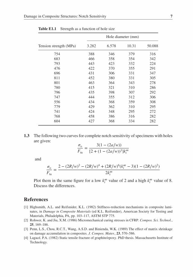
Table E1.1 Strength as a function of hole size
Hole diameter (mm)
Tension strength (MPa) 3.282 6.578 10.31 50.088
754 388 346 379 316683 466 358 354 342793 443 423 332 224476 422 370 355 291696 431 306 331 347811 452 380 331 305801 463 364 343 278780 415 321 310 286796 435 398 307 292747 444 355 312 306556 434 368 359 308779 429 362 310 295741 424 348 295 272768 458 386 316 282604 427 368 334 282
1.3 The following two curves for complete notch sensitivity of specimens with holesare given:
𝜎o
Ftu=
3(1 − (2a∕w))[2 + (1 − (2a∕w))3]k∞t
and
𝜎o
Ftu=
2 − (2R∕w)2 − (2R∕w)4 + (2R∕w)6(k∞t − 3)(1 − (2R∕w)2)2k∞t
Plot them in the same figure for a low k∞t value of 2 and a high k∞t value of 8.Discuss the differences.
References[1] Highsmith, A.L. and Reifsnider, K.L. (1982) Stiffness-reduction mechanisms in composite lami-
nates, in Damage in Composite Materials (ed K.L. Reifsnider), American Society for Testing andMaterials, Philadelphia, PA, pp. 103–117, ASTM STP 775.
[2] Rohwer, K. and Jiu, X.M. (1986) Micromechanical curing stresses in CFRP. Compos. Sci. Technol.,25, 169–186.
[3] Penn, L.S., Chou, R.C.T., Wang, A.S.D. and Binienda, W.K. (1989) The effect of matrix shrinkageon damage accumulation in composites. J. Compos. Mater., 23, 570–586.
[4] Lagacé, P.A. (1982) Static tensile fracture of graphite/epoxy. PhD thesis. Massachusetts Institute ofTechnology.


2Holes
One of the most common stress risers in a composite structure is a hole. The presenceof holes is inevitable in an airframe. Even though assembly methods other than fasten-ing are used through increased co-curing and adhesive bonding, some fastener holesare always present. In addition, lightening holes (to reduce weight), holes to accom-modate systems equipment (hydraulics, electrical, etc.) and window and access doorcutouts are ever present (Figure 2.1). Finally, holes (punctures) created by tool drops,runway debris or other forms of damage also occur during service.Knowing how a composite structure responds in the presence of holes is, therefore,
very important for generating robust and damage-tolerant designs. There is one addi-tional reason for understanding how the strength of a composite structure is affectedby the presence of a hole: Holes can be used to model other more complex forms ofdamage. Treating impact damage or through-thickness cracks as holes of equivalentsize can simplify the design and analysis of such structures.There are different types of holes depending on their shape and whether they are
loaded or not. In addition to circular holes which will be the focus of this chapter,there are elliptical holes or cutouts and holes of irregular shape caused by high-speeddamage (for example, ballistic damage). In terms of loading, one can distinguishbetween unloaded holes, fastener holes with bearing and torque-up loads and filledholes where the filler material is typically the shank of an un-torqued fastener which,being much stiffer, enforces a nearly circular shape on the hole circumference anddoes not allow it to elongate. These are all shown in Figure 2.2.It is important to note that fastener holes tend to lose their torque-up over time.
One extreme case is shown in Figure 2.3. Here, a nut and bolt were used to fastentwo pieces of a (bismaleimide) composite plate. Prior to torquing-up the bolt, twoback-to-back flat surfaces were machined on the bolt shank, and strain gauges wereinstalled. The readings of the back-to-back strain gauges were monitored over time,and they are shown as a percentage of the initial strain reading in Figure 2.3.
Modeling the Effect of Damage in Composite Structures: Simplified Approaches, First Edition. Christos Kassapoglou.© 2015 John Wiley & Sons, Ltd. Published 2015 by John Wiley & Sons, Ltd.
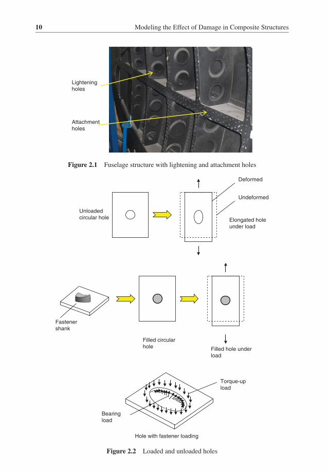
10 Modeling the Effect of Damage in Composite Structures
Attachment
holes
Lightening
holes
Figure 2.1 Fuselage structure with lightening and attachment holes
Unloaded
circular hole Elongated hole
under load
Filled circular
hole Filled hole under
load
Undeformed
Deformed
Torque-up
load
Bearing
load
Fastener
shank
Hole with fastener loading
Figure 2.2 Loaded and unloaded holes

Holes 11
0
10
20
30
40
50
60
70
80
90
100
0 200 400 600 800 1000 1200
Time (hours)
% T
orq
ue-
up
Gage 1
Gage 2
Back-to-
back gages
Figure 2.3 Loss of torque-up over time
The data in Figure 2.3 show a drastic reduction in the strain in the bolt as afunction of time. This corresponds to a proportional loss of torque-up. Within10 days, the torque is down to ∼30% of its initial value. After that the reduction ismuch slower. These data correspond to a regular screw and nut. Typical fastenersfor aircraft applications show significantly less reduction. Nevertheless, over thedecades corresponding to the life of an aircraft, such loss of torque-up is notuncommon. Reduced torque-up translates to reduced bearing strength capability. Forthis reason, it is common to design bolted joints assuming very little or no torquevalues corresponding to ‘finger-tight’ fasteners.In general, but not always, filled hole tension (FHT) is lower than open hole tension
(OHT) [1] while filled hole compression (FHC) is higher than open hole compression(OHC). Designing conservatively in the presence of holes would then, at a minimum,require FHT and OHC tests to establish the lowest values to be expected in service.At the same time, FHT and FHC can be used to define the limits of a bearing-by-passcurve for a specific laminate, as shown schematically in Figure 2.4.If there is a single member with a finger-tight fastener, that is, there is no second
member that the fastener attaches to, then all the applied load P by-passes the fastenerand comes out as load P at the other end of the same member. If the load is tensile,this corresponds to the FHT case. If it is compressive, it corresponds to the FHC case.Both are shown on the vertical axis of Figure 2.4.In a single lap joint with a single fastener, all the load P in one bolted member is
transmitted through the fastener to the other member. This means that there is no loadby-passing the fastener. The entire load becomes bearing load or bearing stress, whichcorresponds to a point on the horizontal axis in Figure 2.4. The bearing stress P/(Dt),

12 Modeling the Effect of Damage in Composite Structures
Bearing
strength
PP
P – P1
P – P1
P1
P1
Bypass
strain
FHT
FHC
Bearing
stress
Figure 2.4 Notional bearing by-pass curve for a laminate
where D is the fastener diameter and t the thickness of the member in question, is tobe compared to the bearing strength of the laminate used.If there are at least two fasteners connecting two members, then only a portion P1
of the total load is transmitted to the other plate through the first fastener, as shownin Figure 2.4. The remaining load P−P1 by-passes the first fastener and reaches thenext fastener. If there are only two fasteners, all of it is transmitted through the secondfastener to the second member. If there are more than two fasteners, then, again, aportion is transmitted through the second fastener and the remainder by-passes to thenext fastener. For each of these ‘interior’ fasteners, there is a combination of bearingstress and by-pass strain that causes failure of the joint. For example, in Figure 2.4,the second fastener has a bearing stress (P− 2P1)/(Dt) since the net load transmittedthrough that fastener is P−P1 (by-pass load after the first fastener) minus P1 (by-passload after the second fastener). The by-pass strain is P1/Em where Em is the axialstiffness of the member.Analyses of holes with fastener loads have been presented by several authors and
are not the focus of this chapter, for example [2–6] with designmethods and guidelines[7–9]. The emphasis here will be on open holes. They correspond to a relatively simplecase which can give insight into themore general case of the loaded hole. And, in somecases, open holes are convenient to use in damage tolerance programs of compositestructures. First because, as already mentioned, other types of damage such as cracksor impact damage may conservatively be modelled as holes of equivalent sizes (see,for example, Section 5.6.1), and, second, because they can help establish limit loadcapability of a structure. A small hole, typically 6.35mm in diameter, is consideredvisible damage and, as such, it is a limit load requirement for a composite structure.Certification of a composite structure requires demonstration that the structure canmeet limit load in the presence of visible damage. Therefore, even if a hole is notpresent in the structure, showing that the structure can meet limit load with a 6.35-mmhole can help demonstrate its damage tolerance capability.


![Document Change History - AUTOSAR · 4.3.3 [ATS_COMLIN_00750] Testing The Dut For LIN Frame Reception ..... 30 4.3.4 [ATS_COMLIN_00751] Start Of Reception Is Indicated When Slave](https://static.documents.pub/doc/80x56/5f68e204fbd25e2aee4b02ac/document-change-history-autosar-433-atscomlin00750-testing-the-dut-for-lin.jpg)
