Page 1
PEER REVIEWED
Modeling the Evolution of Residual Stresses in Thermally SprayedYSZ Coating on Stainless Steel Substrate
Ahmed Fardan1 • Rehan Ahmed1
Submitted: 9 May 2018 / in revised form: 1 March 2019
� The Author(s) 2019
Abstract This study is based on Eulerian method to model
residual stresses for yttrium-stabilized zirconia coating
applied to stainless steel substrate. A commercially avail-
able finite element software ABAQUS/Explicit is used to
conduct this study. Single and multiple-particle impact
analyses were carried out, and the residual stress data have
been reported. The analysis is performed for two different
values of thermal contact resistance and the through-
thickness residual stress profiles obtained within the coat-
ing for single particle are tensile, while the substrate has a
mixture of tensile and compressive residual stresses. For
multiple impact model, the residual stress data have been
presented for substrate with and without cooling. The
residual stresses within the coating without substrate
cooling are mostly tensile while the substrate is compres-
sive. The residual stresses within the coating with substrate
cooling are mostly tensile with compressive stresses on the
top of the coating, while the substrate consists of com-
pressive stresses. The obtained residual stresses are com-
pared with experimental and analytical data.
Keywords ABAQUS � Eulerian � finite element modeling �heat transfer � residual stress � solidification � thermal spray
Introduction
Thermal spray technology comprises a group of coating
processes in which finely divided metallic or nonmetallic
particles are deposited in molten or semi-molten condition
to form a coating. The coating material may be in the form
of powder, ceramic rod, wire or molten material. For
plasma spraying, the particle is heated up to or above its
melting point and is made to impact the substrate at
moderate velocity (100-300 m/s) (Ref 1). The invention of
thermal spray credit goes to MU Schoop (1911), who
received patents along with several collaborators to com-
mercialize the process (Ref 1). The need for coatings has
increased over the past few years since it improves func-
tional performance; reduces wear due to abrasion, erosion
and corrosion; extends the component life by rebuilding the
worn part; and reduces cost by applying expensive coating
over cheaper material (Ref 1-7). Understanding of lamella
bonding, formation of microstructural features and residual
stresses in the finished parts are some of the technological
challenges. This paper deals with the evolution of residual
stresses of YSZ particle from the point of impact of lamella
particle until it has cooled down as the building block of
coating microstructure.
To achieve uniform properties in thermally sprayed
components, it requires careful control of particle diameter,
particle impact velocity and temperature. It is cost-effec-
tive to optimize the operating parameters using computa-
tional methods rather than experiments due to the high
operational costs of the experiment. The first experimental
observations of droplet impacting substrate were performed
by Worthington Ramsden (1903) (Ref 8). Worthington
observed and recorded the splashing and fingering of milk
and mercury droplets impacting a smooth substrate. The
first known numerical modeling of splashing of liquid drop
& Rehan Ahmed
[email protected]
Ahmed Fardan
[email protected]
1 School of Engineering and Physical Sciences, Heriot-Watt
University, Edinburgh EH14 4AS, UK
123
J Therm Spray Tech
https://doi.org/10.1007/s11666-019-00856-2
Page 2
was performed by Harlow and Shannon (1967) using
Marker and Cell technique (MAC) (Ref 9). With the
development of computing power, computational methods
have been widely used to model thermal spray droplet
impact.
Table 1 represents some of the particle and substrate
parameters obtained from the literature for various droplet
impact models. Most of the thermal spray droplet impact
models available in the literature deal with heat transfer,
solidification, formation of pores etc. while not dealing
with evolution of residual stresses. Lagrangian, smoothed
particle hydrodynamics (SPH), Eulerian, coupled Eulerian–
Lagrangian (CEL) and computational fluid dynamics
(CFD) are some of the methods employed to model droplet
impact. Previously, Lagrangian method was employed to
model cold spray coatings, and some of the works can be
found in (Ref 10-14). The drawbacks of using Lagrangian
method are that the model is mesh-sensitive (requires fine
mesh and increases calculation time), rebound of particles
during multiple-particle impact and above a certain particle
velocity, the program terminates due to excessive distortion
of elements. Mesh regeneration in this case is of limited
use as the distorted mesh is also on the contact surface, and
contact mechanics algorithm overrides mesh distortion.
SPH is a mesh-free method which is suitable to model high
distortion spray process (Ref 10), works presented in (Ref
15-17) are modeled using SPH method. Additionally, SPH
is able to overcome the rebound phenomenon experienced
in Lagrangian method (Ref 10). Recently, Eulerian method
has been widely used to model droplet impact and some of
the works can be found in Ref 10, 11. The numerical
models using Eulerian methods were more comparable to
the experimental observations than the Lagrangian model
approach, and hence, Eulerian method is widely used to
model single and multiple impact thermal spray processes
(Ref 10). Eulerian mesh allows the material to flow within
the fixed grid and is suitable to model fluids and molten
materials. The combination of Eulerian and Lagrangian is
known as CEL (coupled Eulerian–Lagrangian) and it
overcomes the above-mentioned disadvantages. Earlier
computational models focused on particle diameter of
2-5 mm and particle velocity of 1-5 m/s for the ease of
comparison with experiments. In reality, the particle
diameter is in the order of micrometers (10-60 lm) and the
impact velocity is around 100-300 m/s (Ref 18-22).
The most advanced finite element simulation for un-
melted solid particles impact can be found in Ref 11 for
copper particle impacting copper substrate. Due to the
limited computational resources, some of the earlier works
presented in Ref 3, 18, 23 are limited to 2D axisymmetric
simulations which hinders the extent of the study that can
be performed on the models, such as the splat morphology
of the droplets deposited. With further development of
faster processing machines and advancement in simulation
software, 3D models were widely published and some of
them can be found in Ref 20, 21, 24-26. A sequential
droplet impingement analysis was carried out in Ref 20
where formations of detached rings were reported, which
were caused due to the momentum gained by the impact of
the second droplet. This also led to fragmentation (satellite
droplets). While the work presented in Ref 24 looks at the
number of fingers caused when a droplet impacts a surface
using Rayleigh–Taylor (RT) instability theory, the com-
putational results were in good agreement with experi-
mental results. The study of heat transfer and solidification
are crucial elements for the study of splat morphology and
some of the works can be found in Ref 21, 26. The work
presented by Fard et al. (Ref 26) studied the heat transfer of
a tin droplet impacting stainless steel substrate and per-
formed experiments to validate their results. The work
presented in Ref 21 extends the work done in Ref 26, by
studying the heat transfer of normal and incline impact.
Experimental and numerical simulation of single and
multiple Nickel particle impacting stainless steel substrate
was performed by Fard et al. (Ref 27) while including the
effect of heat transfer and solidification for the simulations.
Observations of splashing were recorded from the experi-
mental observations for Nickel particles impacting stain-
less steel substrate for substrate temperature of 563 K
while no splashing was observed for substrate temperature
of 673 K. However, in numerical simulations increasing
the substrate temperature didn’t make much of a difference
in splat morphology but increasing the thermal contact
resistance drastically changed the morphology. Another
notable assumption by Xue et al. was that the thermal
contact resistance value need not be provided to the model,
it can be varied through substrate roughness and thermal
conductivity (Ref 28). Although different modeling tech-
niques and advancement in computational efficiency have
significantly improved the splat modeling in thermal spray
coatings, the technological challenge of fine-tuning the
material parameters such as very high strain rates, work
hardening, high cooling rates and temperature-dependent
physical parameters require further work. This coupled
with challenges in attaining experimental data which is
predominantly limited to post-deposition process makes
the validation of the numerical models difficult.
Residual stresses are formed during the thermal spraying
of coating on a substrate. Residual stresses affect the
adhesive strength, cohesive strength, thermal shock resis-
tance, thermal fatigue life, corrosion resistance, wear
properties and service life of coatings (Ref 4, 29-35). There
are two types of residual stresses—deposition stress (oc-
curring at micro-scale) and post-deposition stress (occur-
ring at macro-scale). Deposition stress is caused due to
rapid cooling and solidification of splat, peening action
J Therm Spray Tech
123
Page 3
Table
1Summaryofsomeoftheparticleandsubstrate
param
etersavailable
intheliterature
fornumerical
simulationofthermal
spraydropletim
pact
Particle
Substrate
Sim
ulated
time
period
HT
RS
Method
Notes
References
Material
Diameter
Velocity
(m/s)
Initial
temp
(K)
Final
temp
(K)
Material
Initial
temp
(K)
Final
temp
(K)
YSZ
30lm
80lm
100-240
3250
…SS
423
…0.45ls
77
CELABAQUS/Explicit
Flatteningdegreeincreasesifthesolidcore
is
smallerandplastic
deform
ationislarger
ifthe
core
isbigger.
Ref
58
YSZ
20lm
180
3400
2300
SS
1200
1600
10ls
47
FEPSdeveloped
byICA
Coolingofmolten
particleisdominated
byconductionbetweenparticleand
substrate.Solidcore
decreases
flattening
degree
Ref
59
YSZ
50lm
10
3400
500
SS
300
600
96.7
ms
47
ANSYSFLUENT
Entire
particlewas
simulated
(notaxisymmetric)
withdetails
offreezing-inducedbreakupphenomenon
Ref
60
Tin
(Sn)
2.7
mm
1513
505
SS
298
423
17.3
ms
47
RIPPLEcode
2D
fixed
gridEulerian
Compared
simulationwith
experim
ent.Liquid–solidcontact
anglesareused.Particle–substrate
contact
resistance
Ref
21
2.2
mm
2.35
513
513
SS
298
373
5.1
ms
Perform
edinclineim
pact(458)
Tin
(Sn)
2.1
mm
4519
420
SS
298
…7.5
ms
47
SIM
PLE
QUICK
Surfacestructure
ofprevious
dropletaffectstheseconddroplet
Ref
20
Ni
100lm
50-300
……
Rigid
surface
……
2.4
ls7
7LS-D
yna(Lagrangian)
Increase
velocity
increasesflattening
degree.
Alflattensquicker
than
Ni
Ref
23
Al
50lm
1.6
ls
Al
3.92mm
3903
673
H13tool
steel
473
653
8.5
ms
47
RIPPLEcode
2D
fixed
gridEulerian
Alwas
ingoodagreem
ent
whileNiwasn’t.Contact
resistance
modeled
throughconductivityand
roughness
Ref
28
Ni
50lm
72
1927
…SS
293
…3ls
Ni
60l m
73
1873
…SS
563
673
… …10ls
47
RIPPLEcode
2D
fixed
gridEulerian
Perform
edsingle,double
and
multiple-particleim
pact.Form
ationoffingers
andsplashingiscauseddueto
early
solidificationandto
overcomethiscontact
resistance
isincreased.tempofsubstrate
didn’t
haveeffect
onsplash
Ref
27
TwoNi
60lm
48
2323
…467
…10ls
Multiple
Ni
40-80lm
40-80
1873-2273
…293
…26ls
Pleasenote
that
theabovesummarized
inform
ationwas
obtained
from
therespectivereferencesistrueto
thebestoftheauthor’sknowledge
CE
LcoupledEulerian–Lagrangian,
FE
PSfiniteelem
entprogrammingsystem
,IC
AInstitute
forComputerApplications,
QU
ICK
quadraticupwardinterpolation,
SSstainless
steel,
HTheat
transfer,
RSresidual
stress,
msmillisecond
J Therm Spray Tech
123
Page 4
Table
2Summaryofresearches
wheredifferenttechniques
arecompared
(experim
ental,numerical
andanalyticalmethods)
usedto
evaluateresidual
stresses
inYSZcoatings
Coating
Substrate
AM
FEM
Experim
entalvalidation
Process
Notes
References
Material
Thickness(m
m)
Tem
p(K
)Material
Thickness(m
m)
Tem
p(K
)XRD
MR
CM
ND
YSZ
0.2
…Steel
2.5
*423
77
47
77
APS
RSonthecoatingplaneis
15±
10MPa.
Thestress
values
inYSZspecim
enareverylowin
magnitudeandsometim
esclose
tozero
Ref
47
YSZ
*0.58
…SS
Al
Castiron
*0.22
*0.42
*0.42
358
423
483
74
74
77
APS
RSonYSZcoatingvariesfrom
100MPato
-150MPa.
RSonSSsubstrate
isaround
-250MPa.
TheRSis
tensile
onthetopof
coatingandbecomes
compressivecloserto
the
particle–substrate
interface
Ref
52
YSZ
0.5
3203
3307
3649
SS
Inconel
718?
BC
1.5
1.6
?0.2
432
594
683
1033
74
47
47
APS
RSonthesubstrate
variedfrom
-500MPacloserto
thesurface
toabout?
50MPathroughthe
thickness
Ref
51
YSZ
0.3
…Al
6328
383
523
77
47
77
APS
RSonthesurfaceofYSZcoatings
weretensile
innature
with
maxim
um
valueof30-40MPa
Ref
54
YSZ
0.4
…BC
Ni-alloy
0.1
10
348
423
573
773
47
47
77
APS
Coat
(40.1-6.7
MPa)
Sub(-
3to
1.3
MPa)
Coat
(31.2-14MPa)
Sub(-
2to
0.7
MPa)
Coat
(13.2-30.2
MPa)
Sub(3
to-
0.7
MPa)
Coat
(-11.2to
-50.2
MPa)
Sub(11.2
to-
7MPa)
Ref
53
AM
analyticalmodel,
FE
Mfiniteelem
entmethod,
XR
Dx-ray
diffractionmethod,
MRmaterialremoval,
NDneutrondiffraction,
CM
curvature
measurement,
CScarbonsteel,
SSstainless
steel,
RSresidual
stress,
TB
Cthermal
barrier
coating(Y
SZ?
BC),
YS
Zyttrium-stabilized
zirconia,
BCbondcoat
(NiCrA
lY),
AP
Satmospheric
plasm
aspraying,
Co
atcoating,
Su
bsubstrate
J Therm Spray Tech
123
Page 5
(impact) of droplets on a pre-deposited layer or due to high
thermal gradients developed (Ref 36). Post-deposition
stress is caused by the cooling of the splats to room tem-
perature and due to the mismatch of coefficient of thermal
expansion (CTE) of the coating and substrate. Substrate
geometry and surface treatment also influence the evolu-
tion of residual stresses (Ref 37-39).
Residual stresses are measured experimentally using
various methods. Some of the frequently used methods are
x-ray diffraction (XRD), in situ curvature measurements,
neutron diffraction and incremental hole-drilling methods.
XRD is not able to measure residual stresses in the coat-
ing/substrate interface due to the limited penetration of the
x-rays (Ref 40). XRD can give inaccurate stress values due
to uncertainties in determining elastic parameters (Ref
41, 42). Despite these limitations, XRD has been widely
used by many researchers and has been validated with
other methods (Ref 43-47). Neutron diffraction utilizes
high-energy neutrons which are allowed to penetrate the
sample, and the scattering caused by the atoms and nuclei
is collected and analyzed (Ref 40). The cost of obtaining
sufficient and accurate residual stress data using neutron
diffraction is high (Ref 48). In situ curvature measurement
is another form of experimental measurement for residual
stress. The change in substrate curvature and temperature is
used to predict the residual stresses (Ref 49, 50). It is the
only experimental technique that can track deposition and
post-deposition stresses separately (Ref 40).
The work presented in Ref 51 by Mutter et al. used
in situ curvature measurement to predict residual stresses
developed due to the impact of YSZ particle on various
substrates while employing the XRD and hole-drilling
methods to obtain the residual stress depth profiles in
stainless steel. The residual stresses were compressive
(- 500 MPa) in nature closer to the interface and then had
a gradual change to tensile stresses (50 MPa) through the
thickness of the SS substrate. Unfortunately, there was no
information of residual stress in the YSZ coating. Montay
et al. (Ref 52) employed the incremental hole-drilling
method to determine the residual stresses developed due to
thermal spraying of YSZ on various substrates for different
substrate initial temperatures. It was concluded that the
change in substrate temperature had little or no influence
on the residual stresses for cast iron substrate but had a
drastic influence for aluminum and stainless steel sub-
strates. For higher substrate temperatures, the residual
stresses in the coating are compressive in nature. For
stainless steel substrate at 423 K, the through-thickness
residual stress of the coating is tensile closer to the surface
(100 MPa) and then follows a very low magnitude of stress
(- 10 to ? 10 MPa) and then becomes compressive
(- 150 MPa) closer to the particle–substrate interface. The
residual stress on stainless steel is compressive in nature
(- 250 MPa). Matejicek et al. (Ref 47) used XRD method
to analyze residual stresses developed due to deposition of
various coating material (YSZ, Mo, NiCrAlY and Ni) of
different thicknesses on steel and Al substrates. Notably the
in-plane residual stress for the YSZ coating has low stress
values (average 15 ± 10 MPa) and sometimes close to
zero. Possible explanation being that the quenching and
thermal mismatch stress having opposite signs and cancel
Fig. 1 (a) Computational model of YSZ particle and SS substrate
(highlighted in red color) depicting the mesh resolution, (b) Compu-
tational model domain with boundary conditions where boundary
A-B-C-D is given XSYMM boundary condition, boundary A-D-E-F
is given ZSYMM boundary condition and bottom surface A-F-B is
restricted movement in all directions (Color figure online)
Table 3 Details of mesh and elements for validation model (CEL
method)
Solver used ABAQUS/Explicit
Method CEL
Element type—substrate C3D8R
Element type—particle EC3D8R
No. of elements—particle 1,279,104
No. of elements—substrate 247,590
J Therm Spray Tech
123
Page 6
each other out (Ref 53, 54). Another possible explanation is
being stress relaxation due to the formation of micro-cracks
(Ref 47). Wang and Xiao (Ref 55) employed Cr 3? fluo-
rescence spectroscopy to determine residual stresses in
Al2O3/YSZ coatings. It was found that the macro-com-
pressive residual stresses were high (- 500 to - 300 MPa)
for coating thickness less than 20 lm. and theoretical
model was presented to validate this behavior. Scardi et al.
(Ref 54) studied the effect of deposition temperature on the
microstructure of YSZ coating on Al substrate using XRD.
It was concluded that the surface of the coating was always
in tension (30-40 MPa). Levit et al. (Ref 53) performed
residual stress analysis using XRD for YSZ coating on Ni-
based alloy for various substrate temperatures. It was found
that the stresses changed from tensile (40 MPa) to
compressive (- 20 MPa) as the temperature was increased
and employed mathematical model to verify the results. It
was seen that the residual stresses developed in the YSZ
coating and Ni substrate is directly related to the substrate
temperature. A problem common to all experimental
methods is that they give average stress values which
cannot be used to predict the micro-stresses (or localized
stresses) that often occur near areas of stress concentration
and longer duration is required to optimize spray process
experimentally. Hence, numerical simulation (FEM) has
been the prime focus to model residual stresses developed
in thermal spray coatings (Ref 56).
Most of the numerical models present in the literature to
determine residual stresses involve the study of the post-
deposition stress, and it is assumed that the splat has
completed its flattening process (finite element birth and
death method). However, the models presented in the lit-
erature suffer from various issues and the results are
inaccurate qualitatively and quantitatively. Some of the
models that deal with post-deposition residual stresses
could be found in Ref 29, 30, 57. The review provided by
Clyne et al. (Ref 33) and Abubakar et al. (Ref 40) can be
referred for further discussion of development of residual
stresses. Table 2 provides details of residual stress for
different YSZ coatings on various substrates along with the
various techniques used to measure the residual stress with
their magnitudes.
This paper builds upon the previous work done by Zhu
et al. (Ref 58) for molten YSZ particle impacting a stain-
less steel substrate. The numerical simulation is performed
to validate the model done by Zhu et al. (Ref 58) using
coupled Eulerian–Lagrangian method (CEL) in ABAQUS/
Explicit. Due to the limited availability of the numerical
models in the literature that provides deposition and post-
deposition residual stress analysis, heat transfer model is
simulated while including the effect of coefficient of
thermal expansion (CTE) using pure Eulerian method in
ABAQUS/Explicit.
Fig. 2 Comparison of radial temperature distribution of YSZ particle
used in this paper with temperature distribution used in the validation
paper by Zhu et al. (Ref 58). Normalized radial distance is the
distance from the center of the particle up to the particle periphery
divided by the particle radius at the respective points
Table 4 Comparison of material properties used for the CEL and
Eulerian model
CEL model Eulerian model
YSZ SS YSZ SS
Young’s modulus 7 4 4 4
Poisson’s ratio 7 4 4 4
Density 4 4 4 4
Latent heat 4 4 4 4
Thermal conductivity 4 4 4 4
Specific heat 4 4 4 4
Johnson–Cook plasticity 7 4 4 4
Equation of state 4 7 7 7
Dynamic viscosity 4 7 7 7
Thermal expansion 7 7 4 4
CEL coupled Eulerian–Lagrangian, YSZ yttrium-stabilized zirconia,
SS stainless steel
Table 5 Details of mesh and elements for heat transfer model (Eu-
lerian method)
Solver used ABAQUS/Explicit
Method Eulerian
Element type—substrate EC3D8RT
Element type—particle EC3D8RT
No. of elements—particle 440,570
No. of elements—substrate 402,570
J Therm Spray Tech
123
Page 7
Numerical Method
Validation Model: CEL Method
A fully molten YSZ (yttrium-stabilized zirconia) particle of
30 lm diameter impacting stainless steel (SS) substrate
(circular disk of radius 100 lm and height of 37.5 lm) for
impact velocities of 100, 150, 190 and 240 m/s is modeled
using coupled Eulerian–Lagrangian method (CEL) in
ABAQUS/Explicit. Owing to the axisymmetric nature of
the normal impact, a quarter of the 3D model was simu-
lated. Since CEL is based on volume of fluid (VOF)
approach (Ref 59), there is a presence of void material
shown in Fig. 1(a). The boundary conditions used in the
numerical model are shown in Fig. 1(b). The bottom of the
domain (boundary surface A–F–B) was restricted move-
ment in all directions, while the symmetrical boundary
condition in Z-direction and X-direction was applied to the
boundary surfaces A–D–E–F and A–B–C–D, respectively.
The Eulerian and Lagrangian elements were assigned to the
particle and substrate, respectively. Further details of the
element types could be found in Table 3.
For the interaction, ‘‘General contact, All-with-self’’
was defined for the model. And the particle velocity and
temperatures were defined using the ‘‘Pre-defined field.’’
The substrate was preheated to 423 K. Due to the relatively
low thermal conductivity of the YSZ material, a tempera-
ture gradient occurs in the YSZ particle, hence different
temperatures were assigned to various sections of the YSZ
particle ranging from 3067 to 3250 K. The radial temper-
ature distribution given in the model presented within this
paper is shown in Fig. 2 and is compared with temperature
distribution used in the model by Zhu et al. (Ref 58). The
material parameters used in the CEL model for YSZ and
SS are displayed in Table 4. The model was simulated
using dynamic/explicit step with a total step time of 0.7 lswhich was enough for the kinetic energy of the particle to
become closer to zero and complete its flattening process.
The simulation took around 6-7 days on Lenovo�
ThinkCentre workstation with 6 parallel processors.
Heat Transfer Model: Eulerian Method
The heat transfer model was simulated using pure Eulerian
method for a single YSZ particle (diameter of 30 lm)
impacting SS substrate (circular disk of radius 100 lm and
height of 37.5 lm). The particle and substrate parameters
are same as the validation model (‘‘Validation Model: CEL
Method’’ section). The heat transfer model includes the
solidification and the residual stresses developed during
and post-deposition of the particle. The effect of coefficient
of thermal expansion (CTE) was included to study the
macro-residual stresses. The following are the assumptions
considered in the heat transfer model:
1. Surface roughness of the substrate is not considered
2. The particle is assumed to be fully molten
3. Phase transformation is not considered
4. Phase change from liquid to solid is considered
5. The oxidation and impurities in the coating is ignored
6. The intermediate cooling between the layer is ignored
7. Perfect bonding between the coating and substrate is
considered
8. Heat transfer between the coating and substrate is only
through conduction
9. The formation of macro- and micro-cracks in the
coating is ignored
Temperature-dependent elastic parameters were used in
heat transfer model, due to incompatibility of including
equation of state (EOS) and coefficient of thermal expan-
sion (CTE) for the same material within ABAQUS (Ref
59). The material parameters used in Eulerian model for
YSZ and SS are displayed in Table 4. The interactions
were not defined for the model, since ABAQUS� defines
default contact for Eulerian analysis which is a limitation
since thermal contact resistance (inverse of thermal con-
ductance) cannot be defined between the particle and
substrate. However, as stated by Xue et al. (Ref 28) the
thermal contact resistance can be modified by changing the
thermal conductivity. Hence, the thermal conductivities of
the SS and YSZ materials were manipulated to vary the
contact resistance. To observe the solidification and cool-
ing of the molten YSZ, the model was simulated using the
dynamic explicit temperature-displacement step. For fur-
ther details of the elements, refer to Table 5. To reduce the
computational time, the mesh domain was made smaller
and the mesh was refined in the impact region. The sim-
ulation took around 2-3 days on Lenovo� ThinkCentre
workstation with 6 parallel processors.
Multiple Impact Model Without Substrate Cooling
A multiple impact model has been simulated with a total
number of 100 YSZ particles (diameter of 80 lm)
impacting SS substrate (circular disk of radius 100 lm and
height of 37.5 lm) with an impact velocity of 240 m/s for
Case A. In reality, the particles impact in a random manner
to form layers but to reduce computational time the parti-
cles were modeled to impact in the same location and
axisymmetric model has been simulated. The particles
have been preheated to a temperature of 3000 K and the
substrate was preheated to 423 K. The material properties
of the YSZ and SS used in the multiple impact model are
the same as describer earlier in ‘‘Heat Transfer Model:
Eulerian Method’’ section. The model considers heat
J Therm Spray Tech
123
Page 8
transfer using Eulerian thermally coupled brick element
(EC3D8RT) and uses dynamic explicit temperature-dis-
placement step for a total time step of 140 ls. The simu-
lation took around 15 days on Lenovo� ThinkCentre
workstation with 6 parallel processors.
Multiple Impact Model with Substrate Cooling
A multiple impact model has been simulated with a total
number of 100 YSZ particles (diameter of 80 lm)
impacting SS substrate (circular disk of radius 100 lm and
height of 37.5 lm) with an impact velocity of 100 m/s for
Case A. An axisymmetric model has been simulated to
reduce computational time and the particles impact in the
same location. The particles have been preheated to a
temperature of 3000 K, and the top surface of the substrate
was preheated to 423 K while the rest of the substrate was
heated to 298 K to mimic the cooling effects generated in
the experimental setup. The lower temperature of 298 K
was given as a boundary condition to the outer surface, and
this region maintains the same temperature throughout the
simulation to mimic air cooling of substrate during spray-
ing. While, the substrate temperature of 423 K was given
as a pre-defined field and the temperature in this region can
change during the simulation. A smooth temperature gra-
dient in the substrate would be more realistic but due to the
lack of experimental data, a sharp temperature gradient was
used in the model. The material properties of the YSZ and
SS used in the multiple impact model are same as in ‘‘Heat
Transfer Model: Eulerian Method’’ section. The model
considers heat transfer using Eulerian thermally coupled
brick element (EC3D8RT) and uses dynamic explicit
temperature-displacement step for a total time step of
100 ls. The simulation took around 20 days on Lenovo�
ThinkCentre workstation with 6 parallel processors.
Computational Parameters
Mie–Gruneisen Equation of State
Equation of state (EOS) is a thermodynamic equation
describing the state of solid, fluids and even mixtures of
fluids. Mie–Gruneisen EOS is widely used for solid
materials (Ref 60) and it provides the relation between
pressure and volume at a given state of pressure and tem-
perature. Gustav Mie (1903) developed a model to measure
the intermolecular potential for equation of state of high
temperature solids (Ref 61). In 1912, Gruneisen extended
Mie’s model (Ref 62) and his form of equations have been
the starting point for derivation of Mie–Gruneisen EOS.
The thermodynamic behavior, such as pressure and internal
energy of real material can be categorized by the following
two-term relations (Ref 63):
e V; Tð Þ ¼ eref Vð Þ þ eT V ; Tð Þ ðEq 1Þ
Table 6 Material properties
used in the numerical model for
yttrium-stabilized zirconia
(YSZ) and stainless steel (SS)
YSZ SS
Thermal conductivity (solid) 2.32 14.9 W/mK
Thermal conductivity (liquid) 2 33 W/mK
Latent heat 706,800 272,000 J/kg
Solidus temperature 2799 1710 K
Liquidus temperature 2801 1774 K
Density 5890 7900 kg/m3
Specific heat capacity (solid) 580 477 J/(kg K)
Specific heat capacity (liquid) 713 627 J/(kg K)
Young’s modulus 241 200 GPa
Poisson’s ratio 0.32 0.3 –
Coefficient of thermal expansion (CTE) 6.3 9 10-6 1.54 9 10-5 K-1
Johnson–Cook fitting parameter (A) 420 310 MPa
Johnson–Cook fitting parameter (B) 521 1000 MPa
Johnson–Cook fitting parameter (C) 0.07 0.07 …Johnson–Cook fitting parameter (n) 0.184 0.65 …Johnson–Cook fitting parameter (m) 0.0197 1 …Johnson–Cook fitting parameter (eo) 0.418 0.418 …Melting temperature 2988 1673 K
Transition temperature 298 298 K
Speed of sound (liquid) 3000 … m/s
EOS parameter (s) 2.39 … …
J Therm Spray Tech
123
Page 9
p V ;Tð Þ ¼ pref þC Vð Þ
VeT V ; Tð Þ ðEq 2Þ
where V ¼ 1=q denotes the specific volume, T denotes the
temperature, p is the pressure, e is the internal energy and Cis the Gruneisen parameter which represents the thermal
pressure from a set of vibrating atoms (Ref 58). The sub-
script ref represents the parameters at the reference state.
Combining the above two equations of internal energy and
pressure, the Mie–Gruneisen EOS (Ref 64) is obtained:
p � pH ¼ CV
Em � EHð Þ ðEq 3Þ
where pH and EH are pressure and internal energy along the
Hugoniot as functions of only volume, the Mie–Gruneisen
parameter C is defined as:
C ¼ Co
qo
qðEq 4Þ
where Co is material constant and qo is reference density.
EH, Hugoniot energy is given by:
EH ¼ pHg2qo
ðEq 5Þ
where g ¼ 1� q=qoð Þ is the nominal volumetric com-
pressive strain.
p ¼ pH 1� Cog2
� �þ CoqoEm ðEq 6Þ
Linear Us–Up Hugoniot Form
Mie–Gruneisen EOS is represented in linear Us–Up form
using the Rankine–Hugoniot approximation for purposes of
computational mechanics (Ref 65). The EOS in the absence
of dynamic yielding effects or phase transitions, along with
linear fit assumption for shock velocity as function of
particle velocity (Ref 58) is given by Ref 66:
Us ¼ Co þ sUp ðEq 7Þ
where Us represents the shock velocity, Co is the isentropic
speed of sound, Up is the velocity of the particle, s is a
dimensionless parameter which is related to the pressure
derivative of the isentropic bulk modulus (Ref 58). The
final form of the Us–Up equation is given by:
p ¼ qoC2o
1� sgð Þ21� Co
2
� �þ CoqoEm ðEq 8Þ
The speed of sound in YSZ is taken as 3000 m/s and the
dimensionless parameter s is taken as 2.39 (Ref 67, 68).
Johnson–Cook Plasticity Model
When materials are subjected to dynamic loading condi-
tions (such as high velocity impact), a wide range of strain,
strain rate, pressure and temperature are experienced (Ref
69). The Johnson–Cook plasticity model (Ref 69, 70)
provides the elastic–plastic response of the stainless steel
and yttrium-stabilized zirconia (YSZ). Johnson–Cook
Fig. 3 Variation of flattening degree with particle impact velocity for
experimental data by Vardelle et al. (Ref 72), validation data from
numerical simulation by Zhu et al. (Ref 58) with the CEL and
Eulerian data obtained in this paper
Fig. 4 Comparison of final splat morphology for YSZ coating on SS substrate, (a) experimental data by Shinoda and Murakimi (Ref 74),
(b) numerical data by Zhu et al. (Ref 58), (c) CEL data obtained in the current study (bar indicates 50 lm)
J Therm Spray Tech
123
Page 10
model provides material properties that are subject to high
strain rates and high temperature (Ref 70):
r ¼ A þ Benð Þ 1þ C ln _e�ð Þ 1� T�mð Þ ðEq 9Þ
where e is equivalent plastic strain, _e� ¼ _e= _eo is the
dimensionless plastic strain rate and T* is homologous
temperature. The five material constants are A, B, n, C and
m are static yield strength, strain-hardening exponent,
strain-hardening modulus, strain-rate-sensitive coefficient
and thermal-softening exponent. The Johnson–Cook
parameters for stainless steel (SS) and yttrium-stabilized
zirconia (YSZ) are defined in Table 6 along with other
material properties.
Temperature-Dependent Viscosity
Due to the low thermal conductivity, ceramic powder
develops temperature gradient (Ref 71, 72). There is large
temperature difference between the particle and substrate.
Since Mie–Gruneisen EOS is defined for the YSZ particle,
a temperature-dependent viscosity must be defined for
accurate results. Temperature-dependent viscosity is found
in the work done by Vardelle et al. (Ref 72) which is
validated by Shinoda et al. (Ref 73):
l Pa s½ � ¼ 0:1 exp �2:95þ 5993
T
� �ðEq 10Þ
Table 7 Multiplication factor
used for thermal conductivities
for YSZ and SS in ABAQUS�
YSZ SS
Case A 10 10
Case B 1 10
Fig. 5 Calculated temperature
distribution (Kelvin) of YSZ
particle of 30 lm diameter with
a particle temperature of
3250-3067 K and particle
impact velocity of 240 m/s
impacting stainless steel (SS)
substrate with a substrate
temperature of 423 K for
(a) Case A and (b) Case B.
Temperatures above the melting
point (2988 K) are in gray color
(Color figure online)
J Therm Spray Tech
123
Page 11
Results and Discussion
Validation Model
Molten zirconia (YSZ) of particle diameter 30 lmimpacting stainless steel substrate which was preheated to
423 K was simulated using ABAQUS� 6.16 for particle
impact velocity ranging from 100 to 240 m/s, to validate
the model. Due to the low thermal conductivity of zirconia,
the particle develops thermal gradient along the radius of
the sphere (Ref 58, 71). The quantitative validation was
based on variation of flattening degree for different impact
velocities. Flattening degree (f) is the ratio of the diameter
of final splat and the particle diameter prior to the impact.
The obtained results were compared with experimental
data (Ref 72) and numerical simulation by Zhu et al. (Ref
58) on the basis of flattening degree. Figure 3 depicts the
comparison of the experimental and validation data with
the data obtained within this paper. The numerical data
from the literature exhibit linear behavior showing that the
flattening degree increases with the increase in impact
velocity (Ref 58) while the experimental data obtained are
highly scattered. For an impact velocity, the flattening
degree varies from 1 to 5, showing the highly unpre-
dictable nature of experimental results. The flattening
degree obtained from the CEL and Eulerian model in this
paper is found to be in close agreement with the experi-
mental and numerical data. However, the flattening degree
obtained from CEL has higher flattening degree at higher
velocities, the data obtained from Eulerian model’s pre-
diction of flattening degree are in better agreement with
numerical data obtained by Zhu et al. (Ref 58). The final
splat shape obtained was compared with the experimental
data by Shinoda and Murakimi (Ref 74) and numerical data
by Zhu et al. (Ref 58) which are in good agreement
(Fig. 4). The final splat shapes have a thick central splat
with an uneven formation of fingers in the periphery due to
rapid heat transfer. The formation of micro-cracks is
observed in ceramic materials which are formed due to
residual stress relaxation and the formation of macro-
cracks is due to the relaxation of expansion mismatch stress
(Ref 1). The formation of cracks is seen in the experimental
splat (Fig. 4a) which are micro-cracks in the center which
is caused due to the stress relaxation. The modeling of
thermo-mechanical simulation along with the fracture
mechanics phenomenon brings along many complications
and most of the commercially available softwares are not
able to perform simulation of this complexity. Hence, the
numerical model simulated in this paper considers only the
thermo-mechanical simulation.
Heat Transfer Model
The heat transfer model of YSZ impacting SS with impact
velocity of 240 m/s was simulated using Eulerian method
in ABAQUS/Explicit. The cooling of the splat is governed
by three modes of heat transfer, namely conduction (to the
substrate), convection and radiation (to the surrounding
gas). The heat transfer model presented in this paper con-
siders conduction as the only mode of heat transfer as it is
dominant over convection and radiation. The heat transfer
from the droplet to the surrounding gas is ignored as the
heat transfer magnitude is three orders lower than heat
transfer to the substrate (Ref 27). Due to the unavailability
of interaction properties in Eulerian method in ABAQUS,
thermal gap conductance couldn’t be provided to the
model. From the experimental study by Vardelle et al., the
cooling rates for zirconia (8 wt.% Y2O3) coating on smooth
steel substrate were estimated to be approximately
100-400 K/ls (Ref 72). Hence, the original thermal con-
ductivities were varied to match the cooling rates obtained
by Vardelle et al. (Ref 72). The assumption by Xue et al.
(Ref 28) that the thermal contact resistance (inverse of
thermal conductance) can be varied using surface rough-
ness and thermal conductivity is used in the favor to justify
the manipulation of the thermal conductivity in this model.
Table 7 shows the two cases, Case A and Case B, for
which simulations were performed.
Droplet Impact, Spreading and Solidification
The evolution of the splat morphology of YSZ impacting at
240 m/s on SS substrate for Case A and Case B is depicted
in Fig. 5. The various time intervals from the instant of the
impact up to complete spreading are represented next to the
respective images. When a droplet impacts a surface, it
would do one of the two main processes, ‘‘the particle may
impinge, spread and then solidify or it may deform,
impinge and then splash.’’ The splashing is experienced
due to either low heat transfer which leads to fragmentation
or due to freezing-induced breakup due to very rapid heat
transfer as indicated in (Ref 75). Case A (Fig. 5a) has a
more pronounced effect of freezing-induced break up since
both YSZ and SS conductivity were multiplied by 10
which leads to very rapid heat transfer. As the droplet is
spreading radially outwards, if it has enough momentum it
jets over the solidified layer leading the splat to reach an
unstable point and breaks into smaller fragments. In both
the cases, it is seen that the droplet has completed the
spreading mechanism approximately at 0.5 ls and fol-
lowing that the substrate absorbs the heat which leads to
the cooling of the splat.
For Case B (Fig. 5b), it is noticed that it experiences less
freezing-induced breakup phenomenon when compared
J Therm Spray Tech
123
Page 12
Fig. 6 Residual stresses (MPa)
acting in the XZ plane for
substrate initial temperature of
423 K with YSZ particle
impacting at 240 m/s with the
initial temperature of the
particle from 3250 to 3067 K
for Case A (a) Residual stresses
on the YSZ particle (sectional
isometric view), (b) residual
stresses on the SS substrate
(front view). Tensile stresses are
represented in color spectrum
and compressive stresses are
represented in gray/black color
(Color figure online)
Fig. 7 Residual stresses (MPa)
acting in the XZ plane for
substrate initial temperature of
423 K with YSZ particle
impacting at 240 m/s with the
initial temperature of the
particle from 3250 to 3067 K
for Case B (a) residual stresses
on the YSZ particle (sectional
isometric view), (b) residual
stresses on the SS substrate
(front view). Tensile stresses are
represented in color spectrum
and compressive stresses are
represented in gray/black color
(Color figure online)
J Therm Spray Tech
123
Page 13
with Case A. This is due to the comparatively slower rate
of heat transfer between the splat and the substrate since
only the conductivity of YSZ was multiplied with a factor
of 10, while the conductivity of SS material was left at the
original conductivity values which makes the thermal
conductance value lower. At time instant of 0.12 ls, assoon as the droplet impacts the substrate, there are for-
mations of very tiny satellite droplets. This is also due to
sudden heat transfer, which causes the momentum of the
molten droplet to overcome the solidified layer and reach
an unstable condition leading to the formation of these
droplets. Comparing the cooling rates of Case A and Case
B, it is seen that the splat cools down relatively faster for
Case A and most of the splat has obtained a uniform
temperature value ranging from 423 to 635 K with the
exceptions of some fragments in the outer region that are at
a relatively higher temperature. Whereas for Case B, it is
seen that the outer region of the splat is still at higher
temperature range of 2800 K at the end of time instant of
6 ls. This shows the slower rate of cooling for Case B even
though it was run at twice the time step of Case A, showing
that the splat requires extra time to completely cool down.
There have been experimental claims that the splat
morphology is affected by the substrate temperature and
that above a critical temperature known as transition tem-
perature (TT) (Ref 1) the obtained splats are less prone to
splashing. The experimental observations by Shinoda and
Murakami (Ref 74) of YSZ droplets impacting quartz glass
at various substrate temperatures predicted that the transi-
tion temperature was between 513 and 673 K. However,
the transition temperature varies for each substrate mate-
rial. The numerical simulation done by Xue et al. (Ref 28)
for metallic droplets impacting substrates using variable
thermal contact resistance concluded that for a particular
thermal contact resistance, increasing the substrate tem-
perature did not reduce the splashing experienced by the
splat. There have been experimental reports that increasing
the temperature of the substrate increases the thermal
contact resistance by the formation of oxide layer which is
the main reason due to which droplets experience lesser
degree of splashing (Ref 76). Hence, increasing substrate
temperature in numerical models does not affect the results
as oxide layer formation is ignored and thermal contact
resistance is varied.
Evolution of Residual Stress for Single Particle
The evolution of residual stresses for the YSZ coating on
SS substrate for impact velocity of 240 m/s for Case A is
depicted in Fig. 6. The in-plane stresses acting on the XZ
plane are plotted and the values of the stresses in the legend
are in MPa. The contours are plotted for the YSZ coating
post-spreading. In thermal spray literature, the stresses
developed due to the plastic deformation of the particle on
the substrate or on previously deposited layer are known as
peening stress (Ref 1). Due to the nature of the reaction
forces induced due to the impact, peening stresses are
usually compressive in nature (Ref 40). At the time instants
of 1.02 and 1.20 ls for Fig. 6(a), the bulk of the YSZ
particle experiences tensile stresses (up to 50 MPa) on the
top surface with very minor regions in the lower surface
having compressive stresses (- 50 to - 200 MPa), while
the substrate at these time instants develop large magni-
tudes of compressive residual stress (- 200 to
- 500 MPa) around the region of impact. The periphery
and the center of the substrate experiences very low levels
of tensile stresses (up to 50 MPa). At time instant of 1.5 ls,the tensile stresses in the YSZ coating increases slightly
and is within the range of 50-100 MPa with the lower
region developing high compressive stresses (- 200 to
- 500 MPa). The region of tensile stresses acting in the
center of the substrate expands radially and is within the
range of 100-150 MPa. After 1.5 ls, there is an overall
effect of tensile stresses observed in the particle and a
combination of tensile and compressive stress in the
Fig. 8 Through-thickness residual stress distribution for YSZ coating
and SS substrate at different time instants for YSZ particle with
impact velocity of 240 m/s in the XZ plane (in-plane stresses),
(a) Case A and (b) Case B
J Therm Spray Tech
123
Page 14
substrate, which is caused due to the quenching stress.
Quenching stresses are developed due to the sudden
solidification of flattened molten particles from melting
point to room temperature (Ref 1, 40). The sudden solidi-
fication and shrinkage occurring at the micro-scale within
the splat causes the formation of tensile stresses due to
thermal mismatch stress and constrained shrinkage of the
splat due to interfacial bonding (Ref 1). The thermal gra-
dients developed through the thickness for thick coatings at
macro-scale cause the substrate to bend and distort (de-
pendent on the degree of thermal mismatch). The thermal
gradient is more harmful for ceramic coatings (such as
YSZ) due to the low thermal conductivity (Ref 1).
For time instants of 1.8-3 ls, post-deposition mismatch
stresses are dominant over the peening and quenching
stresses. Occurring at a macro-scale, post-deposition mis-
match stress is primarily caused due to the difference in the
properties (CTE, coefficient of thermal expansion) of the
coating and substrate material (Ref 40). Post-deposition
mismatch stresses are often known to have highest mag-
nitudes and affect the overall residual stresses significantly.
For ceramic coatings, the post-deposition mismatch stress
is usually overall compressive in nature, which is the
outcome of the substrate residual stresses from 0.48 lsonwards. The stresses are compressive due to the lower
CTE of the YSZ when compared with SS.
The evolution of residual stresses for the YSZ coating
on SS substrate for impact velocity of 240 m/s for Case B
is depicted in Fig. 7. The in-plane stresses acting on the XZ
plane is plotted, and the values of the stresses in the legend
are in MPa. The contours are plotted for the YSZ coating
post-spreading. At the time instant of 1.08 ls, majority of
the coating surface is tensile (up to 50 MPa) with a minor
ring-like region of compressive stresses (up to - 50 MPa).
The lower surface of the YSZ coating has some regions
with compressive stress (up to - 200 MPa), while the
substrate has mostly compressive stresses acting on the
surface (- 200 to - 500 MPa) with a circular region in the
center with tensile stress (150-200 MPa). Following
1.08 ls, the residual stress acting in the YSZ coating do not
change significantly with the only exception of a small
ring-like region with slightly higher tensile stress range
(50-100 MPa). The residual stresses acting in the substrate
surface are mostly compressive with the circular tensile
stress region growing in magnitude as time progresses with
the highest magnitude of around 500-600 MPa at the final
time instant (6 ls). There isn’t a significant change in the
magnitude for the single splat coating for the different
Cross-sectional view Magnified cross-sectional view
ResidualStress (MPa)
C
S
Fig. 9 Cross-sectional residual
stress contour plots (in MPa) for
the analysis performed for
substrate without cooling for
YSZ coating (17.3 lmthickness) on SS substrate
(37.5 lm thickness) for particle
impact velocity of 240 m/s.
Tensile stresses are represented
in color spectrum, and
compressive stresses are
represented in black color.
Coating (C) is represented in red
box and substrate (S) in black
box (Color figure online)
Fig. 10 Comparison of through-thickness residual stress distribution
for YSZ coating (thickness 17.3 lm) on SS substrate (37.5 lm)
without substrate cooling obtained from the current study for impact
velocity of 240 m/s with the stress profile obtained by hole-drilling
method by Montay et al. (Ref 52). Note: The coating thickness of
YSZ coating by Montay et al. was 590 lm and the SS substrate was
5000 lm. For comparison purposes, they are plotted in the same
graph
J Therm Spray Tech
123
Page 15
cases (Case A and Case B). However, it is seen that the
nature of the stresses are highly transient for Case A while
for Case B there isn’t noticeable change throughout dif-
ferent time instants.
Through-Thickness Residual Stresses For Single Particle
The through-thickness residual stress profiles in the XZ
plane (in-plane stress) for Case A and Case B are shown in
Fig. 8(a) and (b), respectively, at different time intervals.
For the ease of representation, the stresses are plotted for
different time intervals post the spreading of the droplet.
Two vertical axes are plotted to show the residual stresses
on the particle and substrate separately. For time instant of
1.2 ls for Case A, the residual stress profile of the YSZ
coating is compressive on the top surface and then gradu-
ally becomes tensile through the thickness. Following
1.2 ls, the residual stress acting in the coating is mostly
tensile and the stresses are found to increase with each time
instant. The maximum and minimum residual stress in the
coating is 38 and - 3 MPa, respectively. At time instant of
1.2 ls, the residual stress acting in the substrate is com-
pressive at the interface (- 150 MPa) and then has a sharp
decrease through the thickness (- 400 MPa). Following
that, the stress profile has a sharp increase to obtain tensile
stress value of 50 MPa and then a drop to achieve com-
pressive stress of - 50 MPa. The stress profile then has
minimum variations and is mostly tensile with stress range
of 19-25 MPa. At the substrate interface, the stress value
becomes higher with the increase in time instant but other
than that the overall stress profile has minimum variation.
The through-thickness residual stress for Case B is
shown in Fig. 8(b). The residual stresses acting within the
coating are mostly tensile with a maximum stress of
65 MPa. At time instant of 1.8 ls, the stress acting on the
top surface is low tensile stress (10 MPa) and then reaches
a maximum peak value of 40 MPa followed by a dip
through the thickness (25 MPa). The coating stress profile
for the following time instants have a similar behavior with
the values being slightly different with the final time instant
having the highest magnitude. The residual stress acting in
the substrate is tensile at the interface and then becomes
compressive which is then followed by a tensile peak. The
highest tensile stress in the substrate (445 MPa) occurs at
time instants 5.1 and 6 ls while the highest compressive
stress (- 305 MPa) occurs at time instants of 1.8 and
2.7 ls. Comparing the behavior of Case A and Case B for
coating stress profile, it is seen that they are quite similar in
nature with the exception of higher stress values for Case
B. Additionally, the compressive stress highest value is
lower for Case B (about - 300 MPa) than Case A
(- 409 MPa).
Residual Stresses in Thick Coating Without Substrate
Cooling
A sequential impact of YSZ particles impacting SS sub-
strate was carried out to obtain a thick coating. A total of
100 particles with an impact velocity of 240 m/s was
simulated using axisymmetric conditions to reduce com-
putational time and a final thickness of 17.3 lm was
obtained. The reason for obtaining such a small thickness
of the coating is due to the smaller mesh domain which
caused the splashing of the coating outside the mesh
domain due to the high impact velocity of the particle.
Increasing the size of the mesh domain wouldn’t aid in
obtaining a thicker coating as in experimental methods the
thermal spray gun is passed over a pre-determined path
Cross-sectional view Magnified cross-sectional view
ResidualStress (MPa)
C
S
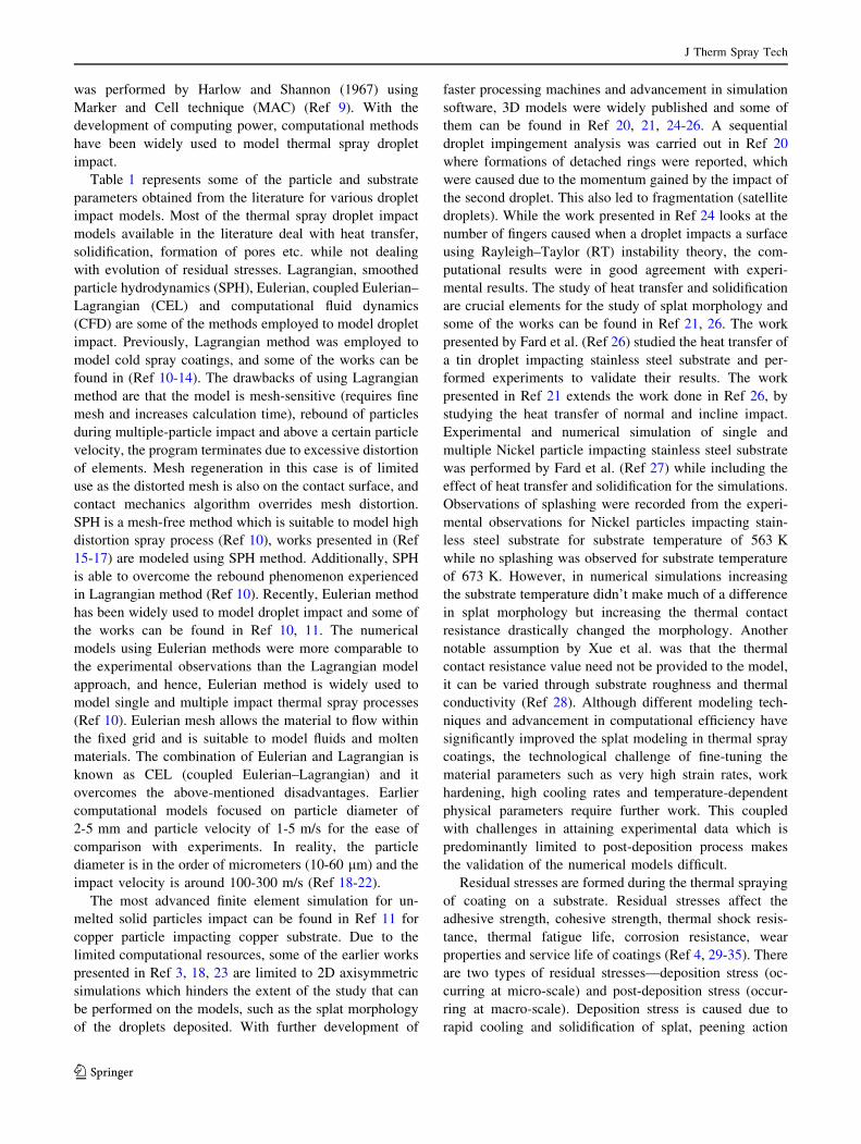
Fig. 11 Cross-sectional
residual stress contour plots (in
MPa) for the analysis performed
for substrate with cooling for
YSZ coating (61.3 lmthickness) on SS substrate
(37.5 lm thickness) for particle
impact velocity of 100 m/s.
Tensile stresses are represented
in color spectrum and
compressive stresses are
represented in black color.
Coating (C) is represented in red
box and substrate (S) in black
box (Color figure online)
J Therm Spray Tech
123
Page 16
over the substrate. So, the molten particles impact on a
solidified coating layer as opposed to impacting on a
molten layer of coating in the numerical simulation. The
final residual stress contours acting in the cross section of
the coating and substrate obtained from the finite element
package are shown in Fig. 9 for substrate without cooling.
It is seen that the bulk of the coating experiences tensile
stresses (90-230 MPa) with compressive stresses (up to
- 250 MPa) occurring closer to the coating/substrate
interface. The substrate experiences tensile stresses on the
top surface with a maximum tensile stress range of
200-250 MPa occurring closer to the interface followed by
a small region of low levels of tensile stress. The rest of the
substrate has compressive stresses (- 50 to - 250 MPa).
A magnified view of the coating/substrate system is also
shown in Fig. 9. It is seen that there is a large variation in
the magnitude and nature of stresses in the coating and
substrate. The through-thickness residual stress distribution
of the thick YSZ coating and SS substrate is shown in
Fig. 10. The residual stress measurements were performed
farther from the surfaces on which the symmetric boundary
conditions were given as it was seen that they influenced
the residual stress profiles. The residual stress acting on the
YSZ coating is mostly tensile with stress range of 100 MPa
to 250 MPa. The residual stress acting on the substrate is
tensile closer to the interface and then becomes compres-
sive through the thickness with a maximum stress of
- 195 MPa. The residual stress distribution obtained by
Montay et al. (Ref 52) using incremental hole-drilling
method is also plotted for comparison in Fig. 10. The YSZ
coating and SS substrate used in (Ref 52) were about
590 lm and 5 mm and is plotted in the same graph for the
sake of comparison with the numerical data from the cur-
rent study. The results indicate that the nature and mag-
nitude of residual stresses within the SS substrate is
comparable for the current numerical data and the hole-
drilling method (HDM).
Differences were observed for the YSZ coating for the
numerical data and HDM. The numerical data predicted the
stresses within the coating to be mostly tensile while the
hole-drilling method predicted it to be tensile on the sur-
face and then through thickness compressive. The possible
explanation for this residual stress behavior in the substrate
is due to the influence of measurement technique on the
residual stress profile. HDM is known to affect the residual
stress behavior by the formation of micro-cracks in the
vicinity of the hole (Ref 4). Recently, neutron diffraction
measurement techniques have widely been used due to
their non-destructive and high penetration capabilities and
a comparative study of neutron diffraction and hole-drilling
method was carried out by Ahmed et al. (Ref 4). It was
concluded that the hole-drilling method predicts residual
stress in the top layer of the coating reasonably well but
through the thickness there is a significant difference in
these experimental values of the residual stresses. The
residual stresses predicted by HDM are macro-stresses.
Neutron diffraction (ND) techniques are much more
effective in predicting residual stresses and the profile
obtained from ND technique can be compared with stress
profile from numerical data. However, there is very limited
work available on neutron diffraction for YSZ and SS
combination.
Residual Stresses in Thick Coating with Substrate Cooling
The residual stress analysis was performed with the sub-
strate cooling. A total of 100 particles with an impact
velocity of 100 m/s was simulated using axisymmetric
conditions to reduce computational time and a final
thickness of 61.3 lm was obtained. The preheated tem-
perature (423 K) to the substrate was applied only to the
top of the substrate, and the rest of the substrate was given
a lower temperature (298 K) in the numerical model to
mimic the cooling of the substrate similar to experimental
conditions. This was done to enhance the cooling of the
substrate since the substrate for the model described in
‘‘Residual Stresses in Thick Coating Without Substrate
Cooling’’ section had poor cooling effects. The final
residual stress contours acting in the cross section of the
coating and substrate obtained from the finite element
package are shown in Fig. 11 for the case of substrate with
cooling. The coating experiences mostly compressive
stresses on the top surface with the middle region experi-
encing tensile stresses followed by the lower region (closer
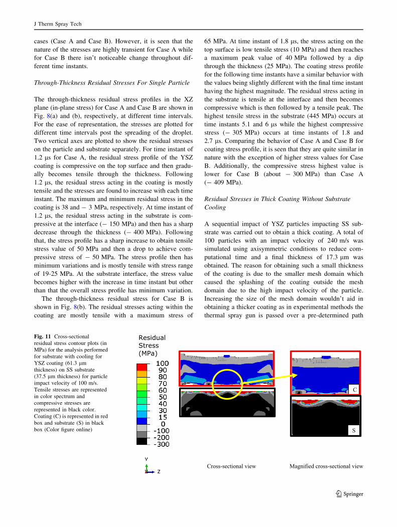
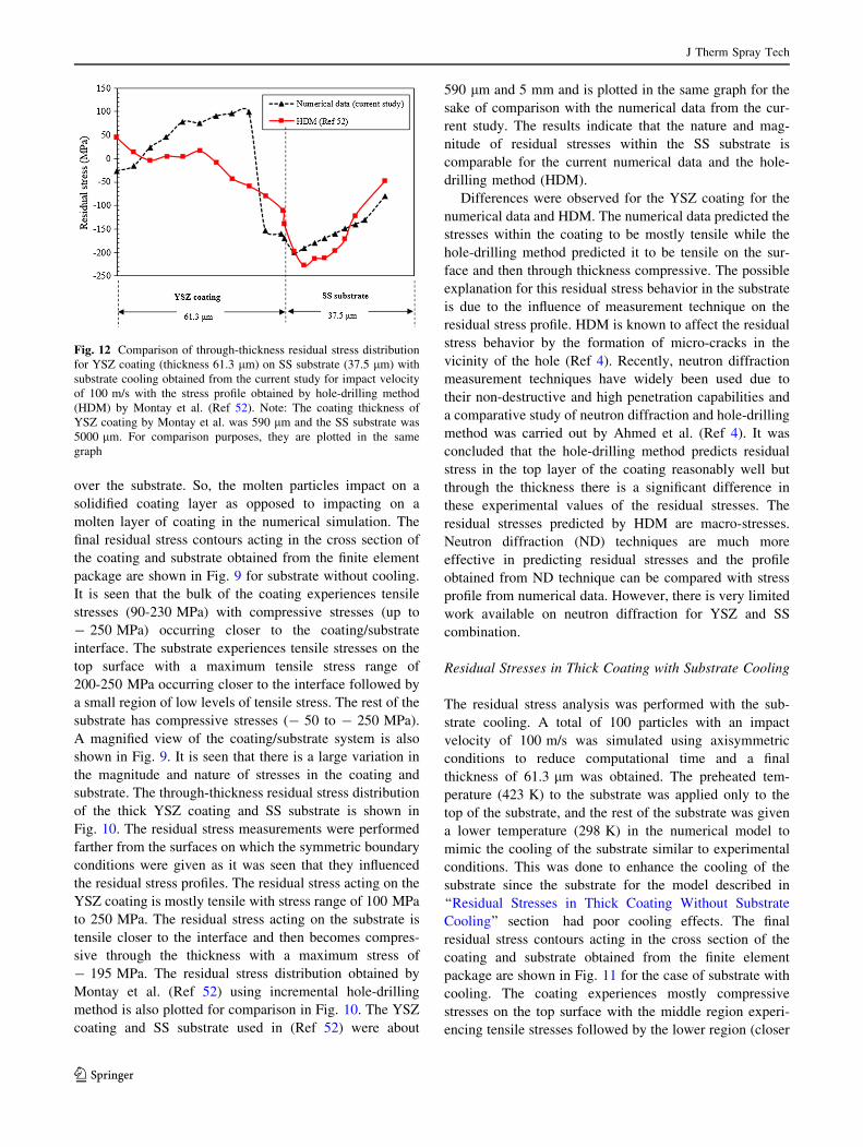
Fig. 12 Comparison of through-thickness residual stress distribution
for YSZ coating (thickness 61.3 lm) on SS substrate (37.5 lm) with
substrate cooling obtained from the current study for impact velocity
of 100 m/s with the stress profile obtained by hole-drilling method
(HDM) by Montay et al. (Ref 52). Note: The coating thickness of
YSZ coating by Montay et al. was 590 lm and the SS substrate was
5000 lm. For comparison purposes, they are plotted in the same
graph
J Therm Spray Tech
123
Page 17
to interface) experiencing compressive stresses. The sub-
strate mostly has small regions of tensile stresses closer to
the interface while the rest of the substrate experiences
compressive stresses. A magnified view of the coat-
ing/substrate system is also shown in Fig. 11. It is seen that
there is a large variation in the magnitude and nature of
stresses in the coating and substrate. Comparing the mag-
nified view, it is seen that the coating has a mixture of
compressive and tensile stress for both substrate with
cooling (Fig. 11) and for substrate without cooling (Fig. 9).
The substrate is seen to have compressive stresses closer to
the center for substrate with cooling (Fig. 11), while there
are high tensile stresses for substrate without cooling
(Fig. 9).
The through-thickness residual stress profile for YSZ
coating and SS substrate is shown in Fig. 12. The
residual stress acting in the YSZ coating is compressive
on the top of the coating (- 27 MPa) and then becomes
tensile (100 MPa) through the thickness. The residual
stress profile then becomes compressive closer to the
substrate/coating interface (- 170 MPa). The substrate
consists of mostly compressive stress (- 197 MPa), and
the magnitude of stress reduces through the thickness.
The stress profile obtained by Montay et al. (Ref 52) is
also plotted in Fig. 12 for comparison. It is seen that the
numerical study predicted the coating residual stress to
be mostly tensile while the HDM predicted it to be
mostly compressive. The substrate residual stress profile
obtained in the current study is comparable to the HDM
profile. It is seen that the numerical study predicted the
coating residual stress (with and without cooling,
‘‘Residual Stresses in Thick Coating Without Substrate
Cooling’’ and ‘‘Residual Stresses in Thick Coating with
Substrate Cooling’’ sections) to be tensile while the
HDM results (Ref 52) predicted it to be compressive.
This can be attributed to the influence of measurement
technique as discussed above. Another possible expla-
nation for the different nature of the residual stress with
HDM (Ref 52) is the different ratio of thickness of
coating to substrate. The future research would consist of
following the same thickness of the substrate/coating or
following the similar coating to substrate thickness ratio
and spray parameters like the experiment for quantitative
validation.
Comparison with Coefficient of Thermal Expansion Model
The macro-residual stresses obtained from numerical sim-
ulation were compared with the coefficient of thermal
expansion model for a two-layer system. Residual stresses
due to thermal expansion mismatch stress in a two-layer
system could be based on the following equation assuming
that the coefficient of thermal expansion (CTE) does not
vary with DT (Ref 77, 78):
rC ¼ 1
tC
aS � aCð Þ:DT1�mC
tCECþ 1�mS
tSES
" #ðEq 11Þ
where r, E, t, a and DT are thermal stress, Young’s
modulus, Poisson’s ratio, CTE and temperature change,
respectively. The subscripts ‘‘c’’ and ‘‘s’’ are properties of
coating and substrate, respectively. Upon the YSZ particle
impacting the substrate, the particle temperature is taken as
3250 K. The temperature change DT in Eq 11 was taken as
2827 K, as it was assumed that the particle cools down to
the temperature of the substrate, 423 K. The thermal
stresses calculated using Eq 11 for the YSZ coating and SS
substrate for three distinct coating thicknesses are shown in
Table 8. It is seen that the stresses calculated using ana-
lytical methods give high thermal stress values. It is also
seen that the thermal stresses acting in the coating reduces
as the thickness increases which is likely not seen in the
experimental data. The stresses calculated using Eq 11 are
inaccurate since it assumes perfect bonding between the
particle and substrate (Ref 4, 79). Phase change of the
materials (Ref 80) and the variation of Young’s modulus,
Poisson’s ratio and CTE with temperature are not
considered.
Table 8 Calculated thermal stress (analytical method) for YSZ coating and SS substrate for different coating thickness using Eq 11
No. Material Young’s modulus
(GPa)
Poisson’s
ratio
CTE (K-1) Thickness
(lm)
Temperature change
(K)
Calculated thermal stress
(MPa)
1 YSZ Ec = 241 tc = 0.32 ac = 6.3 9 10-6 tc = 2.14 DT ¼ 2827 rc = 8514
SS Es = 200 ts = 0.3 as = 1.54 9 10-5 ts = 37.5 rs = - 485
2 YSZ Ec = 241 tc = 0.32 ac = 6.3 9 10-6 tc = 17.3 DT ¼ 2827 rc = 5798
SS Es = 200 ts = 0.3 as = 1.54 9 10-5 ts = 37.5 rs = - 2675
3 YSZ Ec = 241 tc = 0.32 ac = 6.3 9 10-6 tc = 61.3 DT ¼ 2827 rc = 3011
SS Es = 200 ts = 0.3 as = 1.54 9 10-5 ts = 37.5 rs = - 4922
Subscripts ‘‘c’’ and ‘‘s’’ stand for coating and substrate, respectively, ? ve: tensile, - ve: compressive
J Therm Spray Tech
123
Page 18
Conclusion
A numerical model of residual stress evolution is presented
for single and multiple splats of YSZ coating on SS sub-
strate. The model is in reasonable agreement with the
previously reported experimental (Ref 52, 72) and
numerical investigations (Ref 58). The following were the
main conclusions drawn from the current study:
1. The final splat shape obtained highly depends on the
thermal conductance between the particle and sub-
strate. Higher thermal conductance leads to the
formation of fingers and leads to splashing.
2. For single particle impact, the thermal conductance
used in the model influences the through-thickness
residual stresses obtained in the coating and substrate.
The nature of the stresses is same, but the magnitude
obtained for lower conductance is slightly higher.
3. For multiple impact model without substrate cooling,
the residual stress profile in the coating is only tensile
which is balanced by compressive stresses in the
substrate.
4. For multiple impact model with substrate cooling, the
residual stress in the coating is low compressive on the
top surface and then becomes tensile while the
substrate is mostly compressive.
Open Access This article is distributed under the terms of the
Creative Commons Attribution 4.0 International License (http://crea
tivecommons.org/licenses/by/4.0/), which permits unrestricted use,
distribution, and reproduction in any medium, provided you give
appropriate credit to the original author(s) and the source, provide a
link to the Creative Commons license, and indicate if changes were
made.
References
1. P.L. Fauchais, J.V.R. Heberlein, and M.I. Boulos, Thermal Spray
Fundamentals, Springer, Berlin, 2014, https://doi.org/10.1007/
978-0-387-68991-3
2. M. Zirari, A. Abdellah El-Hadj, and N. Bacha, Numerical
Analysis of Partially Molten Splat during Thermal Spray Process
Using the Finite Element Method, Appl. Surf. Sci., 2010, 256(11),p 3581-3585. https://doi.org/10.1016/j.apsusc.2009.12.158
3. Y. Kumar and S. Kumar, Numerical Modeling of Impact and
Solidification of a Molten Alloy Droplet on a Substrate, Adv.
Mater. Form. Join., 2015. https://doi.org/10.1007/978-81-322-
2355-9
4. R. Ahmed, M.E. Fitzpatrick, and N.H. Faisal, A Comparison of
Neutron Diffraction and Hole-Drilling Residual Strain Measure-
ments in Thermally Sprayed Coatings, Surf. Coat. Technol.,
2012, 206(19-20), p 4180-4185
5. O. Ali, R. Ahmed, N.H. Faisal, N.M. Alanazi, L.M. Berger, A.
Kaiser, F.L. Toma, E.K. Polychroniadis, M. Sall, Y.O. Elakwah,
and M.F.A. Goosen, Influence of Post-treatment on the
Microstructural and Tribomechanical Properties of Suspension
Thermally Sprayed WC-12 wt%Co Nanocomposite Coatings,
Tribol. Lett., 2017, 65(2), p 1-27
6. N.H. Faisal, R. Ahmed, S.P. Katikaneni, S. Souentie, and M.F.A.
Goosen, Development of Plasma-Sprayed Molybdenum Carbide-
Based Anode Layers with Various Metal Oxides for SOFC, J.
Therm. Spray Technol., 2015, 24(8), p 1415-1428
7. R. Ahmed, O. Ali, N.H. Faisal, N.M. Al-Anazi, S. Al-Mutairi,
F.L. Toma, L.M. Berger, A. Potthoff, and M.F.A. Goosen, Slid-
ing Wear Investigation of Suspension Sprayed WC-Co
Nanocomposite Coatings, Wear, 2015, 322-323, p 133-150
8. W. Ramsden, The Royal Society is Collaborating with JSTOR to
Digitize, Preserve, and Extend Access to Proceedings of the
Royal Society of London�, 1903, 72, p 156-164, Www.jstor.org.
Accessed 12 Dec 2017
9. F.H. Harlow and J.P. Shannon, The Splash of a Liquid Drop, J.
Appl. Phys., 1967, 38(10), p 3855-3866
10. S. Yin, X.F. Wang, B.P. Xu, and W.Y. Li, Examination on the
Calculation Method for Modeling the Multi-Particle Impact
Process in Cold Spraying, J. Therm. Spray Technol., 2010, 19(5),p 1032-1041
11. M. Yu, W.Y. Li, F.F. Wang, and H.L. Liao, Finite Element
Simulation of Impacting Behavior of Particles in Cold Spraying
by Eulerian Approach, J. Therm. Spray Technol., 2012, 21(3-4),p 745-752
12. Y. Li, X. Wang, S. Yin, and S. Xu, Influence of Particle Initial
Temperature on High Velocity Impact Process in Cold Spraying,
Procedia Environ. Sci., 2012, https://doi.org/10.1016/j.proenv.
2012.01.281
13. G. Bae, Y. Xiong, S. Kumar, K. Kang, and C. Lee, General
Aspects of Interface Bonding in Kinetic Sprayed Coatings, Acta
Mater., 2008, 56(17), p 4858-4868
14. B. Yildirim, H. Fukanuma, T. Ando, A. Gouldstone, and S.
Muftu, A Numerical Investigation Into Cold Spray Bonding
Processes, J. Tribol., 2014, 137(1), p 11102
15. M. Zhang, H. Zhang, and L. Zheng, Numerical Investigation of
Substrate Melting and Deformation During Thermal Spray
Coating by SPH Method, Plasma Chem. Plasma Process., 2009,
29(1), p 55-68
16. M.Y. Zhang, H. Zhang, and L.L. Zheng, Simulation of Droplet
Spreading, Splashing and Solidification Using Smoothed Particle
Hydrodynamics Method, Int. J. Heat Mass Transf., 2008, 51(13-14), p 3410-3419
17. M. Zhang, H. Zhang, and L. Zheng, Application of Smoothed
Particle Hydrodynamics Method to Free Surface and Solidifica-
tion Problems, Numer. Heat Transf. Part A Appl., 2007, 52(4),p 299-314. https://doi.org/10.1080/00397910601150007
18. S. Kamnis and S. Gu, Numerical Modelling of Droplet
Impingement, J. Phys. D Appl. Phys., 2005, 38(38), p 3664-3673.
https://doi.org/10.1088/0022-3727/38/19/015
19. S. Shakeri and S. Chandra, Splashing of Molten Tin Droplets on a
Rough Steel Surface, Int. J. Heat Mass Transf., 2002, 45(23),p 4561-4575
20. S. Kamnis, S. Gu, T.J. Lu, and C. Chen, Numerical Modelling of
Sequential Droplet Impingements, J. Phys. D. Appl. Phys., 2008,
41(16), p 165-303. https://doi.org/10.1088/0022-3727/41/16/
165303
21. M. Pasandideh-Fard, S. Chandra, and J. Mostaghimi, A Three-
Dimensional Model of Droplet Impact and Solidification, Int.
J. Heat Mass Transf., 2002, 45(11), p 2229-2242
22. R.K. Shukla, S.K. Yadav, M.H. Shete, and A. Kumar, Numerical
Modeling of Impact and Solidification of a Molten Alloy Droplet
on a Substrate, Adv. Mater. Form. Join., 2015, https://doi.org/10.
1007/978-81-322-2355-9
23. M.E. Aalami-aleagha, S. Feli, and A.R. Eivani, FEM Simulation
of Splatting of a Molten Metal Droplet in Thermal Spray Coating,
J Therm Spray Tech
123
Page 19
Comput. Mater. Sci., 2010, 48(1), p 65-70. https://doi.org/10.
1016/j.commatsci.2009.12.002
24. M. Bussmann, S. Chandra, and J. Mostaghimi, Modeling the
Splash of a Droplet Impacting a Solid Surface, Phys. Fluids,
2000, 12(12), p 3121-3132
25. M. Bussmann, J. Mostaghimi, and S. Chandra, On a Three-Di-
mensional Volume Tracking Model of Droplet Impact, Phys.
Fluids, 1999, 11(6), p 1406-1417. https://doi.org/10.1063/1.
870005
26. M. Pasandideh-Fard, R. Bhola, S. Chandra, and J. Mostaghimi,
Deposition of Tin Droplets on a Steel Plate: Simulations and
Experiments, Int. J. Heat Mass Transf., 1998, 41, p 2929-2945
27. M. Pasandideh-Fard, V. Pershin, S. Chandra, and J. Mostaghimi,
Splat Shapes in a Thermal Spray Coating Process: Simulations
and Experiments, J. Therm. Spray Technol., 2002, 11(2), p 206-
217. https://doi.org/10.1361/105996302770348862
28. M. Xue, Y. Heichal, S. Chandra, and J. Mostaghimi, Modeling
the Impact of a Molten Metal Droplet on a Solid Surface Using
Variable Interfacial Thermal Contact Resistance, J. Mater. Sci.,
2007, 42(1), p 9-18
29. K. Khor and Y. Gu, Effects of Residual Stress on the Perfor-
mance of Plasma Sprayed Functionally Graded ZrO2/NiCoCrAlY
Coatings, Mater. Sci. Eng. A, 2000, 277(1-2), p 64-76. https://doi.
org/10.1016/S0921-5093(99)00565-1
30. V. Teixeira, M. Andritschky, W. Fischer, H.P. Buchkremer, and
D. Stover, Effects of Deposition Temperature and Thermal
Cycling on Residual Stress State in Zirconia-Based Thermal
Barrier Coatings, Surf. Coat. Technol., 1999, 120, p 103-111
31. Z. Xue, A.G. Evans, and J.W. Hutchinson, Delamination Sus-
ceptibility of Coatings Under High Thermal Flux, J. Appl. Mech.,
2009, 76(4), p 41008
32. P. Araujo, D. Chicot, M. Staia, and J. Lesage, Residual Stresses
and Adhesion of Thermal Spray Coatings, Surf. Eng., 2005,
21(1), p 35-40. https://doi.org/10.1179/174329405X30020
33. T.W. Clyne and S.C. Gill, Residual Stresses in Thermal Spray
Coatings and Their Effect on Interfacial Adhesion: A Review of
Recent Work, J. Therm. Spray. Technol., 1996, 5(4), p 401.
https://doi.org/10.1007/bf02645271
34. R. Ahmed, N.H. Faisal, A.M. Paradowska, and M.E. Fitzpatrick,
Residual Strain and Fracture Response of Al2O3 Coatings
Deposited via APS and HVOF Techniques, J. Therm. Spray
Technol., 2012, 21, p 23-40
35. N.H. Faisal, R. Ahmed, A.K. Prathuru, S.P. Katikaneni, M.F.A.
Goosen, and S.Y. Zhang, Neutron Diffraction Residual Strain
Measurements of Molybdenum Carbide-Based Solid Oxide Fuel
Cell Anode Layers with Metal Oxides on Hastelloy X, Exp.
Mech., 2017, 58, p 1-19
36. S. Kuroda, T. Dendo, and S. Kitahara, Quenching Stress in
Plasma Sprayed Coatings and Its Correlation with the Deposit
Microstructure, J. Therm. Spray Technol., 1995, 4(1), p 75-84
37. J. Matejicek, S. Sampath, D. Gilmore, and R. Neiser, In Situ
Measurement of Residual Stresses and Elastic Moduli in Thermal
Sprayed Coatings Part 2: Processing Effects on Properties of Mo
Coatings, Acta Mater., 2003, 51(3), p 873-885
38. M.H. Staia, E. Ramos, A. Carrasquero, A. Roman, J. Lesage, D.
Chicot, and G. Mesmacque, Effect of Substrate Roughness
Induced by Grit Blasting upon Adhesion of WC-17% Co Thermal
Sprayed Coatings, Thin Solid Films, 2000, 377-378, p 657-664
39. R. Gadow, M.J. Riegert-Escribano, and M. Buchmann, Residual
Stress Analysis in Thermally Sprayed Layer Composites, Using
the Hole Milling and Drilling Method, J. Therm. Spray Technol.,
2005, 14(1), p 100-108
40. A.A. Abubakar, A.F.M. Arif, K.S. Al-Athel, S.S. Akhtar, and J.
Mostaghimi, Modeling Residual Stress Development in Thermal
Spray Coatings: Current Status and Way Forward, J. Therm.
Spray Technol., 2017, 26(6), p 1115-1145
41. O.P. Oladijo, A.M. Venter, L.A. Cornish, and N. Sacks, Surface
& Coatings Technology X-ray Diffraction Measurement of
Residual Stress in WC-Co Thermally Sprayed Coatings onto
Metal Substrates, Surf. Coat. Technol., 2012, 206(23), p 4725-
4729. https://doi.org/10.1016/j.surfcoat.2012.01.044
42. B.S. Yilbas and A.F.M. Arif, Residual Stress Analysis for HVOF
Diamalloy 1005 Coating on Ti-6Al-4V Alloy, Surf. Coat. Tech-
nol., 2007, 202(3), p 559-568
43. T.C. Totemeier and J.K. Wright, Residual Stress Determination
in Thermally Sprayed Coatings—A Comparison of Curvature
Models and X-ray Techniques, Surf. Coat. Technol., 2006,
200(12-13), p 3955-3962
44. Y.C. Yang and E. Chang, Measurements of Residual Stresses in
Plasma-Sprayed Hydroxyapatite Coatings on Titanium Alloy,
Surf. Coat. Technol., 2005, 190(1), p 122-131
45. J. Pina, A. Dias, and J. Lebrun, Study by X-ray Diffraction and
Mechanical Analysis of the Residual Stress Generation During
Thermal Spraying, Mater. Sci. Eng. A, 2003, 347(1-2), p 21-31.
https://doi.org/10.1016/S0921-5093(02)00580-4
46. O. Kesler, J. Matejicek, S. Sampath, S. Suresh, T. Gnaeupel-
Herold, P.C. Brand, and H.J. Prask, Measurement of Residual
Stress in Plasma-Sprayed Metallic, Ceramic and Composite
Coatings, Mater. Sci. Eng. A, 1998, 257(2), p 215-224
47. J. Matejıcek, S. Sampath, and J. Dubsky, X-ray Residual Stress
Measurement in Metallic and Ceramic Plasma Sprayed Coatings,
J. Therm. Spray Technol., 1998, 7(4), p 489-496
48. C. Lyphout, P. Nylen, A. Manescu, and T. Pirling, Residual
Stresses Distribution Through Thick HVOF Sprayed Inconel 718
Coatings, J. Therm. Spray Technol., 2008, 17, p 915-923
49. G.G. Stoney, The Tension of Metallic Films Deposited by
Electrolysis, Proc. R. Soc. Lond. Ser. A Contain. Pap. Math.
Phys. Character, 1909, 82, p 172-175
50. A. Brenner and S. Senderoff, A Spiral Contractometer for Mea-
suring Stress in Electrodeposits, J. Res. Natl. Bur. Stand., 1949,
42(February), p 89
51. M. Mutter, G. Mauer, R. Mucke, R. Vaßen, H.C. Back, and J.
Gibmeier, Investigations on the Initial Stress Evolution During
Atmospheric Plasma Spraying of YSZ by In Situ Curvature
Measurement, J. Therm. Spray Technol., 2016, 25(4), p 672-683
52. G. Montay, A. Cherouat, J. Lu, N. Baradel, and L. Bianchi,
Development of the High-Precision Incremental-Step Hole-Dril-
ling Method for the Study of Residual Stress in Multi-layer
Materials: Influence of Temperature and Substrate on ZrO2-
Y2O38 Wt% Coatings, Surf. Coat. Technol., 2002, 155(2-3),p 152-160
53. B.W.M. Levit and I. Grimberg, Residual Stresses in Ceramic
Plasma-Sprayed Thermal Barrier Coatings: Measurement and
Calculation, Mater. Sci. Eng. A, 1996, 5093(95), p 30-38
54. P. Scardi, M. Leoni, and L. Bertamini, Residual Stresses in Plasma
Sprayed Partially Stabilised Zirconia TBCs: Influence of the
Deposition Temperature, Thin Solid Films, 1996, 278, p 96-103
55. X. Wang and P. Xiao, Residual Stresses and Constrained Sin-
tering of YSZ/Al2O3 composite Coatings, Acta Mater., 2004,
52(9), p 2591-2603
56. J. Zhu, W. Chen, and H. Xie, Simulation of Residual Stresses and
Their Effects on Thermal Barrier Coating Systems Using Finite
Element Method, Sci. China Phys. Mech. Astron., 2015, 58(3),p 1-10. https://doi.org/10.1007/s11433-014-5541-y
57. M. Ranjbar-Far, J. Absi, G. Mariaux, and S. Shahidi, Modeling of
the Residual Stresses and Their Effects on the TBC System after
Thermal Cycling Using Finite Element Method, Ceram. Mater.,
2010, 62(3), p 275-279
58. Z. Zhu, S. Kamnis, and S. Gu, Numerical Study of Molten and
Semi-molten Ceramic Impingement by Using Coupled Eulerian
and Lagrangian Method, Acta Mater., 2015, 90, p 77-87. https://
doi.org/10.1016/j.actamat.2015.02.010
J Therm Spray Tech
123
Page 20
59. Abaqus Analysis User’s Manual, ABAQUS 2016 HTML Docu-
mentation, Dassault Systems, 2016, http://50.16.225.63/v2016/.
Accessed 17 Jan 2018
60. H. Chen, W.H. Tang, X.W. Ran, M.J. Zhang, and Z.H. Xu,
Measurement of the Mie–Gruneisen Equation of State for Poly-
imide, Chin. Sci. Bull., 2013, 58(6), p 585-588
61. G. Mie, Zur Kinetischen Theorie Der Einatomigen Korper, Ann.
Phys., 1903, 316(8), p 657-697
62. E. Gruneisen, Theorie Des Festen Zustandes Einatomiger Ele-
mente, Ann. Phys., 1912, 344(12), p 257-306
63. K.-M. Shyue, A Fluid-Mixture Type Algorithm for Compressible
Multicomponent Flow with Mie–Gruneisen Equation of State, J.
Comput. Phys., 2001, 171(2), p 678-707. https://doi.org/10.1006/
jcph.2001.6801
64. M.H. Rice, R.G. McQueen, and J.M. Walsh, Compression of
Solids by Strong Shock Waves, Solid State Phys. Adv. Res. Appl.,
1958, 6(C), p 1-63
65. M.L. Wilkins, Computer Simulation of Dynamic Phenomena,
Scientific Computation Springer, Berlin, 1999
66. A.L. Ruoff, Linear Shock-Velocity–Particle-Velocity Relation-
ship, J. Appl. Phys., 1967, 38(13), p 4976-4980
67. T. Mashimo, A. Nakamura, M. Nishida, S. Matsuzaki, K. Kusaba,
K. Fukuoka, and Y. Syono, Anomalous Shock Compression
Behavior of Yttria-Doped Tetragonal Zirconia, J. Appl. Phys.,
1995, 77(10), p 5069-5076
68. T. Mashimo, A. Nakamura, M. Kodama, K. Kusaba, K. Fukuoka,
and Y. Syono, Yielding and Phase Transition under Shock
Compression of Yttria-Doped Cubic Zirconia Single Crystal and
Polycrystal, J. Appl. Phys., 1995, 77(10), p 5060-5068
69. G.R. Johnson and W.H. Cook, Fracture Characteristics of Three
Metals Subjected to Various Strains, Strain Rates, Temperatures
and Pressures, Eng. Fract. Mech., 1985, 21(1), p 31-48
70. G.R. Johnson and W.H. Cook, A Constitutive Model and Data for
Metals Subjected to Large Strains, High Strain Rates and High
Temperatures, in 7th International Symposium on Ballistics,
1983, p 541-547.
71. H. Tabbara and S. Gu, Numerical Study of Semi-molten Droplet
Impingement, Appl. Phys. A Mater. Sci. Process., 2011, 104(4),p 1011-1019
72. M. Vardelle, A. Vardelle, A.C. Leger, P. Fauchais, and D. Gobin,
Influence of Particle Parameters at Impact on Splat Formation
and Solidification in Plasma Spraying Processes, J. Therm. Spray
Technol., 1995, 4(1), p 50-58
73. K. Shinoda, Y. Kojima, and T. Yoshida, In Situ Measurement
System for Deformation and Solidification Phenomena of Yttria-
Stabilized Zirconia Droplets Impinging on Quartz Glass Substrate
Under Plasma-Spraying Conditions, J. Therm. Spray Technol.,
2005, 14(4), p 511-517
74. K. Shinoda and H. Murakami, Splat Morphology of
Yttria-Stabilized Zirconia Droplet Deposited via Hybrid
Plasma Spraying, J. Therm. Spray Technol., 2010, 19(3), p 602-
610
75. R. Dhiman, A.G. McDonald, and S. Chandra, Predicting Splat
Morphology in a Thermal Spray Process, Surf. Coat. Technol.,
2007, 201(18), p 7789-7801
76. V. Pershin, M. Lufitha, S. Chandra, and J. Mostaghimi, Effect of
Substrate Temperature on Adhesion Strength of Plasma-Sprayed
Nickel Coatings, J. Therm. Spray Technol., 2003, 12(3), p 370-
376
77. M. Ohring, Materials Science of Thin Films—Deposition &
Structure, Mater. Sci., 2001, https://doi.org/10.1016/b978-
012524975-1/50010-0
78. A.J. Mcginnis, T.R. Watkins, and K. Jagannadham, Residual
Stresses in a Multilayer System of Coatings, JCPDS Int. Cent.
Diffr. Data 1999, 1993, 41(C), p 443-454
79. R. Ahmed, H. Yu, S. Stewart, L. Edwards, and J.R. Santisteban,
Residual Strain Measurements in Thermal Spray Cermet Coat-
ings via Neutron Diffraction, J. Tribol., 2007, 129(2), p 411.
https://doi.org/10.1115/1.2647503
80. N.H. Faisal, R. Ahmed, A.K. Prathuru, S.P. Katikaneni, M.F.A.
Goosen, and S.Y. Zhang, Neutron Diffraction Residual Strain
Measurements of Molybdenum Carbide-Based Solid Oxide Fuel
Cell Anode Layers with Metal Oxides on Hastelloy X, Exp.
Mech., 2018, 58(4), p 585-603. https://doi.org/10.1007/s11340-
017-0298-7
Publisher’s Note Springer Nature remains neutral with regard to
jurisdictional claims in published maps and institutional affiliations.
J Therm Spray Tech
123