Delegating the responsibility of safe driving on an autonomous vehicle needs the autonomous system to be extremely robust. In an attempt to design a robust guidance system for the autonomous vehicle we decided to go refer the most complex system designed which is “humans”. In humans we peculiarly observe that there exists an array of senses we possess that provide the required robustness and efficiency in chores that we perform. It clearly displays that in human beings the various senses we possess precisely complement each other to support a process. Let us take a brief example case shown in figure 1a-b.
Figure 1.a- Human Sensory Perception Figure 1b- Car Sensory Perception
Suppose a human has to navigate from a blue room to a red room in a complex of rooms where the additional information for navigation is that the red room is extremely hot while the blue room is cold. As seen the path the human follows to reach the right destination is V-R-N-J-F-B-C-D path where he uses his eyes for identifying the color. Also the temperature increases as the human approaches the hotter room. This additional sense increases speed of approach and also facilitates choosing the direction and hence the path for reaching undergoes optimization. This indicates that the navigation efficiency increases as an array(in this case two) of sensors which are eyes and skin are used for color detection and temperature sensing respectively. This can now be equated to autonomous navigation system. Suppose a vehicle needs to navigate for place A to place B. Primarily a GPS will be used for navigation by utilizing its co-ordinate information for path determination and tracking. To complement this navigation process we propose to add the element of pedestrian and lane tracking mechanisms for making navigation robust and fast. This is illustrated in figure 1b.
2. Mathematical Modelling for Lane Contention Using SCILAB
It is necessary to do a mathematical modelling for predicting the controller action based on changing inputs. The Model Predictive Control [1] algorithm is used below to take these into account where the inputs used are acceleration (positive and negative), mass, inertia and steering, peer position of vehicles in the neighbourship set whereas the outputs are the positional co-ordinates of the vehicles. Consider the parameters
R:No of Measured Process Variable; S: No of Control Outputs; P: Prediction Horizon; M: Control Horizon.
A: Dynamic Matrix = ; where a11 = Matrix of Step-Response coefficients and
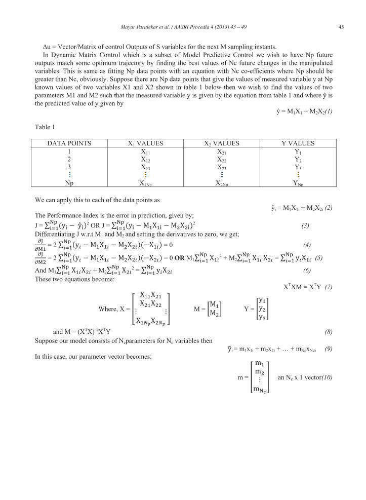
u = Vector/Matrix of control Outputs of S variables for the next M sampling instants. In Dynamic Matrix Control which is a subset of Model Predictive Control we wish to have Np future
outputs match some optimum trajectory by finding the best values of Nc future changes in the manipulated variables. This is same as fitting Np data points with an equation with Nc co-efficients where Np should be greater than Nc, obviously. Suppose there are Np data points that give the values of measured variable y at Np known values of two variables X1 and X2 shown in table 1 below then we wish to find the values of two parameters M1 and M2 such that the measured variable y is given by the equation from table 1 and where is the predicted value of y given by
= M1X1 + M2X2(1)
Table 1
DATA POINTS X1 VALUES X2 VALUES Y VALUES 1 2 3
Np
X11 X12 X13
X1Np
X21 X22 X23
X2Np
Y1 Y2 Y3
YNp
We can apply this to each of the data points as
i = M1X1i + M2X2i (2) The Performance Index is the error in prediction, given by; J = 2 OR J = 2 (3) Differentiating J w.r.t M1 and M2 and setting the derivatives to zero, we get;
= 2 = 0 (4)
= 2 = 0 OR M12 + M2 = (5)
And M1 + M22 = (6)
These two equations become: XTXM = XTY (7)
Where, X = M = Y =
and M = (XTX)-1XTY (8) Suppose our model consists of Ncparameters for Nc variables then
i = m1x1i + m2x2i + … + mNcxNci (9) In this case, our parameter vector becomes:
Similarly, the coefficient matrix becomes: X = Nc x Np matrix (11)
Now, we may define the Performance Index as: J = + X2 (12)
The partial derivative of J with respect to mk is: = 2 + 2 = 0 (13)
For the first parameter m1, this equation can be written as: m1 + m2 + … + mNc = (14)
All these equations can be written in the matrix form as: [XTX + ] = XTY OR m = [ XTX + ]-1XTY (15)
2.1 Step Response Module
Suppose m1 is the step change in the input at t=0 and y1 is the response at t=Ts Then, At t= 0 = 0 At t= Ts = b1 m1 At t= 2Ts = b2 m1 + b1 m2 At t= 3Ts = b3 m1 + b2 m2 + b1 m3 At t= 4Ts = b4 m1 + b3 m2 + b2 m3 + b1 m4 At t= 5Ts = b5 m1 + b4 m2 + b3 m3 + b2 m4 + b1 m5 Similarly, the output for Np instants with Nc changes in the input variable can be written as shown below
This can be written as: (16)
Where B is Np x Ncis the coefficient matrix; is Np x 1is the output vector and is Nc x 1 input vector We define a new Np x Nc matrix A as:
whose elements are related to those of B as follows: aik = bi+1-k with bi = 0 for i Then, the value of the output can be written as:
(17) If there have been Np changes in the manipulated variable during the previous Np steps and if no other
changes were made, the output would change in future because of the old changes in the input. (18)
However, at the current instant, the 0th, we can measure the actual output of the process. If the model were perfect and if there were no disturbances, the actual and predicted values would be equal. The predicted value at the 0th instant is given by:
(19) The difference between and is added to the predicted value at the ith sampling period so that the
response will be improved. (20)
The last expression is used in the DMC calculations where the closed loop response will be given by: (21)
Thus the DMC algorithm finds the best values for the manipulated variables, (AM)newby minimizing a performance index J. By least squares formulation, we can write: ( m)new= [ATA + 2I]-1 AT Y
We then proceed as follows 1-Calculate the Np values of Yol,i from the past values of the manipulated variables and the present
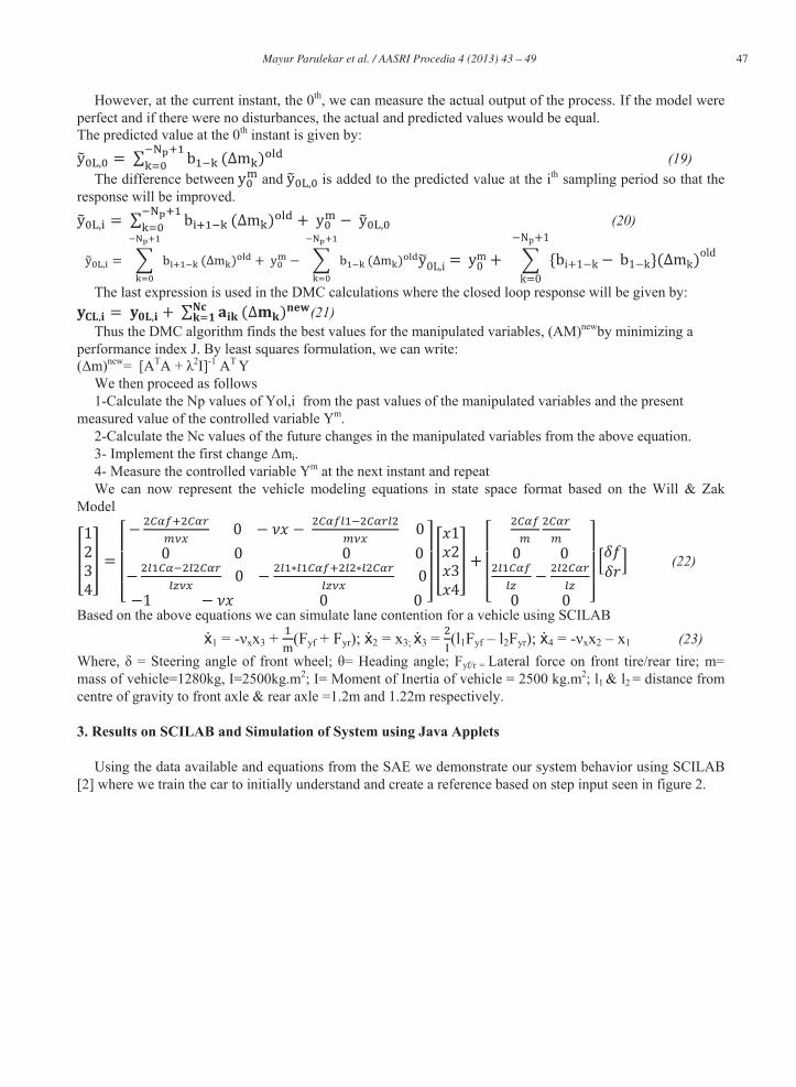
measured value of the controlled variable Ym. 2-Calculate the Nc values of the future changes in the manipulated variables from the above equation. 3- Implement the first change mi. 4- Measure the controlled variable Ym at the next instant and repeat We can now represent the vehicle modeling equations in state space format based on the Will & Zak
Model
(22)
Based on the above equations we can simulate lane contention for a vehicle using SCILAB
1 = - xx3 + (Fyf + Fyr); 2 = x3; 3 = (l1Fyf – l2Fyr); 4 = - xx2 – x1 (23) Where, = Steering angle of front wheel; = Heading angle; Fyf/r = Lateral force on front tire/rear tire; m= mass of vehicle=1280kg, I=2500kg.m2; I= Moment of Inertia of vehicle = 2500 kg.m2; l1 & l2 = distance from centre of gravity to front axle & rear axle =1.2m and 1.22m respectively.
3. Results on SCILAB and Simulation of System using Java Applets
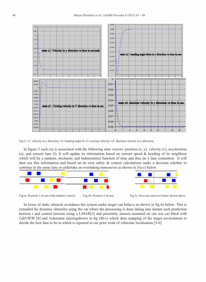
Using the data available and equations from the SAE we demonstrate our system behavior using SCILAB [2] where we train the car to initially understand and create a reference based on step input seen in figure 2.
Fig.2- x1: velocity in y direction; x2: heading angle ; x3: yawing velocity; x4: absolute velocity in y-direction
In figure 3 each car is associated with the following state vectors- position (x, y), velocity (v), acceleration (a), and current lane (l). It will update its information based on current speed & heading of its neighbour which will be a random, stochastic and indeterminist function of time and thus do a lane contention. It will then use this information and based on its own safety & control calculations make a decision whether to continue in the same lane or undertake an overtaking manoeuvre as shown in 3(a-c) below.
Fig3a- Position 1 of cars with random velocity Fig,3b- Position 2 of cars Fig,3c- Previous and next frame shown above
In terms of static obstacle avoidance the system under target can behave as shown in fig.4a below. This is extended for dynamic obstacles using the car where the processing is done taking into instant each prediction horizon t and control horizon using a LiDAR[3] and proximity sensors mounted on our test car fitted with LabVIEW [4] and Ackerman steeringshown in fig (4b-c) which does mapping of the target environment to decide the best lane to be in which is reported in our prior work of vehicular localisation [5-6]
Fig. 4a- static obstacle avoidance manoeuvreFig.4b- Test car in LabFig.4c. CAD layout
4. Conclusions
We have introduced our work with stress on need of more sensing requirements for robust autonomous self-driven and self-aware vehicles. With this, we introduce the concept of lane contention and the need for mathematical modelling based on the reason that software computation being faster can reduce the constraints on hardware. The modelling is used to train the system to initially learn the behaviour of the car from prior references and, with change in the dynamics of the vehicle optimize itself to provide same performance irrespective of hardware weaning thus introducing optimization at run time. We have then validated our work with control of a formation of vehicles using simulation based on results obtained from Scilab computation.
5. References
[1] B.WayneBequette, “ Non-Linear predictive Control using Multi-rate Sampling”, The Canadian Journal of Chemical Engineering Vol.69, Issue 1,pg 136-143 Feb 1991 [2] www.scilab.org [3] M.; Sakai, U.; Ogata, J., "Real-time Pedestrian Detection Using LIDAR and Convolutional Neural Networks," Intelligent Vehicles Symposium, 2006 IEEE , vol., no., pp.213,218, 0-0 0 [4] www.ni.com/labview [5]Parulekar, M.; Shroff, D.; Padte, V.; Nangalia, H.; Metawala, A., "Vehicular localization and Intelligent Transportation Systems,"12th International Conference on Hybrid Intelligent Systems (HIS), pp.306,311 [6] M. Parulekaret al,“QoS Improvement Using NLMPC for Congestion Control and Co-operative Information Processing,” ICIP 2012. ISBN 978-3-642-31686-9