19
SU1 SIEG 1 SMALL MILLING MACHINE MODEL:SU1 INSTRUCTION MANUAL Please read through all the contents and warnings in this safety specification carefully before using the machine.

SU1 SIEG 1
SMALL MILLING MACHINE MODEL:SU1
INSTRUCTION MANUAL
Please read through all the contents and warnings in this safety
specification carefully before using the machine.

SU1 SIEG 2
Important Safety Specification
To operators:
1. To avoid electrical shock and harm, basic safety protection shall be
enhanced when using electric tools, machines and equipments;
2. Keep the environment around the machine clean and tidy, since a
disorderly environment will bring danger;
3. Do not install the machine in places vulnerable to rain or moisture. No
flammable liquid (e.g. petroleum) is allowed near the machine;
4. Children shall stay away from workplace;
5. All the equipments of the machine shall be equipped with safety
grounding devices to protect personal safety;
6. Operators shall keep a clear head, do not operate when tired;
7. Drinking and narcotics may affect one’s judgment, so no operators
with these conditions are allowed to operate;
8. Do not wear loose clothes, neckties or precious jewels to avoid
dangers of being caught by the moving parts.
9. Operators shall wear hard hats to cover long hair.
10. Operators shall wear protective goggles in case that iron filings fly
into the eyes.
11. During the work, operators shall remain in a correct posture and keep
their balance.

SU1 SIEG 3
Contents i. Main technical parameters ……. 4
Technical parameters
Loading list
ii. Appearance and main component diagram of SU1
milling bed ……. 6
iii. Machine installation ……. 7
Basic positioning
Cautions before operation
iv. Driving system ……. 8
v. Operation and maintenance ……. 9
Electrical operation
Mechanical operation
Appendixes vi. Troubleshooting …….12
vii. Circuit diagram …….13
viii. Exploded drawing of parts …….15
ix. Part detail list …….16

SU1 SIEG 4
Brief description
SU1 Series milling bed is a small desktop lifting one, which can be switched to vertical or horizontal bed by changing the position of the power head. The vertical bed can do oblique milling by rotating the power head on the vertical plane. The two modes share one power head. The spindle drive of SU1 Series milling bed adopts infinite variable speeds. Comparing with the traditional gear drive and pulley drive, the synchronous pulley drive has a novel structure, low noise, stable drive and easy operation. The parts it can process have a broad range of application. It has comprehensive functions of vertical milling, horizontal milling, drilling, and boring. It is an ideal machine of family modeling, metal-processing learning and processing and repair.
(Ⅰ) Main technical parameters 1. Maximum drilling capacity 16 mm 2. Face milling capacity 16 mm 3. Surface milling capacity 30 mm 4. Maximum blade-shaped cutter diameter 63 mm 5. Maximum distance from the spindle face to the worktable of vertical milling bed 165 mm 6. Maximum distance from the spindle face to the worktable of horizontal milling bed 130 mm 7. Rotating angle of the spindle carrier of vertical milling bed ±45 degrees 8. Taper hole of spindle MT3 or R8 9. Spindle rotation speed (infinitely variable speed) 0-2500 r/ min ±10% 10. Size of the worktable 460×120 mm 11. Size of T-slot 12 mm 12. Lateral moving distance of the worktable 120 mm 13. Vertical moving distance of the worktable 300 mm 14. Z-directed moving distance of the worktable 105 mm 15. Motor power 500 w 16. Net weight / Gross weight: 95/115 kg

SU1 SIEG 5
Packing List
No. Name Specifications Quantity 1 Milling bed SU1 1 set 2 Operation specifications 1 book 3 Drill chuck and keys B16 1~13mm 1 unit 4 Taper-shank arbor X20206 1 piece 5 Oil can 1 piece 6 Inner hexagon spanner S: 3, 4, 5, 6 1 in each size 7 Double-ended spanner 5.5×7, 10×12 1 in each size 8 Double-ended spanner 14×17, 21×24 1 in each size 9 Hook spanner 22~26 1 piece 10 T-nut X22001 2 11 Gear shift lever X1025200 1

SU1 SIEG 6
(Ⅱ) Appearance and main component diagram
of SU1 milling bed
No. Quantity Name No. Quantity Name
1 1 Base 8 1 Spindle box of vertical milling bed
2 1 Upright post 9 2 Locating locking block
3 1 Lift 10 1 Mounting holes of horizontal milling bed
4 1 Vertical worktable 11 1 Spindle of horizontal milling bed
5 1 Horizontal worktable 12 1 Junction block of horizontal milling bed
6 1 Ram 13 1 Locking lever
7 1 Components of milling head 14 1 Locking mechanism of spindle box
1
3
4
5
9
8
76
2
14
12
7
4
10
11
13

SU1 SIEG 7
(Ⅲ) Machine installation
Basic positioning The whole machine and worktable shall be fixed with four hexagon bolts. Continuous working period and machine accuracy must be taken into consideration. It shall be installed in the proper position to make it available to use. The selection of installation positioning: 1) Rigid worktable shall be padded on a flat adjuster block. 2) In order to avoid the effect of high temperature on the machine, do
not install the machine in sunny places. 3) The machine shall be installed away from dusty and wet places to
avoid corrosion and rust. Important positioning methods
1) Drill four positioning holes on the mounting surface of the worktable. (Notes: in terms of the installing position, hand wheels of the Y-axis shall be considered for easy rotation and operation.)
2) Adjust the machine to a horizontal position. Use four M10 bolts to fix the worktable and the machine.
Before operation When installation is finished, operators shall understand and grasp the basic structure, functions and controlling operations of the machine. Check whether the power source, voltage and the power supply are correct and regular. 1. During installation, all the clamping devices shall be fixed. 2. Check whether the power source and voltage are correct. 3. Before using the machine, fill mechanical lubricating oil to the
sliding surface of the machine. 4. Check the chucks, clamping key and fixed pin on the spindle to
make them under no load. 5. Check whether the driving parts are regular, whether each operating
handles are in right positions, whether the tool clips (drills, milling

SU1 SIEG 8
cutters, etc.) are reliable and whether the processing parts are fixed tightly. Open the spindle box to lock the handle.
6. The spindle circles clockwise to start the machine. 7. When the machine is operating, its electrical devices shall conform
to the working condition and have safety grounding devices. 8. During the operation, notice and control the machine. If any
irregular sign, it shall be stopped and repaired immediately.
(Ⅳ) Driving System
The driving system of the milling bed mainly consists of a synchronous pulley, a spindle bearing, a spindle and a motor, a motor synchronous pulley and a synchronous belt. The direct current motor starts power to work through synchronous pulley of motor, synchronous pulley of spindle and the spindle. The rotation speed is within the specified range of 0-2500 r/min by direct current through the infinite variable speed knob, which allows it to change its speed conveniently.

SU1 SIEG 9
(Ⅴ)Operation and maintenance Electrical operation
H
B
A
C
D
E
F
G
A Power switch
B Speed showing plate
C Overload indicator
D Power indicator
E Potentiometer knob
F Speed showing socket
G Fuse holder
H Power cable
Move the speed-adjusting potentiometer E (equipped with a switch) anti-clockwise to “0”, and plug H into the plug base to connect to the power. At this time, the power green light D is luminous. (Note: if the yellow light C is luminous when the power is on, it indicates that the knob of potentiometer E is not pointed to 0. Each time the machine restarts, the knob E shall be pointed to 0.)

SU1 SIEG 10
The circuit board of the machine has a function of overloaded protection. Once the drilling and milling amount is oversized, the machine will stop automatically, and the yellow light C is luminous; when it restarts, the knob E shall be pointed to 0. Mechanical operation 1. The machine shall stop when installing cutters and parts. 2. Clean the inner hole of the spindle (Morse No. 3) and cone of the cutter. Push the cutter into the inner hole of the spindle and put the bar to tighten the cutter. 3. Put the part to be processed on the worktable, press it and move it horizontally and vertically to the needed position. 4. Loosen the locking handle of the lift and lift the worktable by swaying the handle. 5. Start the machine and select the rotation speed to do drilling and milling. 6. When milling the part, the spindle box and spindle shall be locked. And vertical, horizontal and lift gag shall be locked in case of a change size. The installation and switch methods of vertical and horizontal milling beds
FIG. 1 FIG. 2
3
7
82 4
6
51
3
10 9
4
1
2
8
11

SU1 SIEG 11
The normal bed is a horizontal one. When it switches into a vertical milling bed (as shown in FIG. 2), remove the Junction Block 10 and Spindle 9 and loosen Screw 4 in sequence to remove milling head components; (As shown in FIG. 2) Install Spindle Box 11 in the installing hole behind Ram 8. (Notes: loosen Locking Handle 5 first and make the gap and hole of the locking blocks aligned), loosen Screw 4 and install Milling Head Component 1, then lock Screw 4 to align Locking Handle 5 to 0 and lock it.
After use The power source shall be cut after finishing work. Clean the machine and the environment around it and wipe machine oil on the outside processing face to avoid rust of the surface and the influence on its use and appearance. Gag adjustment After a long period of operation, the gag on the worktable and saddle shall be adjusted to eliminate errors to keep the machine reliable and accurate. Gag parts that need to be adjusted are shown below. 1) Horizontal gag between the worktable and the saddle. 2) Vertical gag between the saddle and the lift. Adjust the gag set screw until the hand wheel is whirled easily and stably, and the worktable does not feel loose. Lock the nut on the set screw to finish the adjustment.

SU1 SIEG 12
Troubleshooting This part includes the most common questions and solutions of this model. No adjustment before the power is off and the motor stops running.
Symptom Possible reasons Improvements The motor cannot start.
1. Does not switch on. 2. Low voltage 3. The motor shuts off or the connecting
parts are loose. 4. The carbon brush of the motor does
not work.
1. Press the emergency stop switch button. 2. Check whether the voltage is right. 3. Check whether all the joints are loose or off. 4. Change the carbon brush.
The fuse or the circuit breaker is off.
1. The wire or plug is short-circuited. 2. The circuit board is short-circuited. 3. The fuse or circuit breaker is not
correct.
1. Check whether the insulated part of the wire or plug is damaged and replace with extension wires.
2. Check whether the joints are loose, are faulty soldered or insulated, and change them in time.
3. Install the right fuse of circuit breaker. The motor is over-heated.
1. The motor is over-loaded. 2. Air circulation in the motor is limited.
1. Decrease the load of the motor. 2. Clean the motor to ensure the air circulation.
The hand wheels of the cross slide or feed slide is too loose.
1. The adjusting screw is not in its place.2. The hand wheel is loose. 3. The screw components are worn or
not in their positions.
1. Tighten the adjusting screw and fill lubricating oil on the bed.
2. Tighten the knob of the hand wheel. 3. Tighten all the loose knobs on the screw
components. The hand wheels of the cross slide or feed slide is too tight.
1. The adjusting screw is rusty. 2. The adjusting screw is too tight. 3. The worktable is dry.
1. Remove the screw, clean the bed and rust on pile joints, fill lubricating oil and re-tighten the screw.
2. Loosen the screw and fill lubricating oil. 3. Fill lubricating oil on the worktable and hand
wheels. The machine stops during the operation.
1. The drilling and milling is too deep. 2. It uses the wrong rotation speed or
feed speed during drilling and milling.
3. The milling cutter is damaged. 4. The motor or carbon brush does not
work. 5. The gear is damaged.
1. Decrease the depth of drilling and milling. 2. Adopt right speed in reference to rotation speed
and feed speed list. 3. Change the milling cutter. 4. Change the carbon brush or the motor. 5. Change the gear.
The surface of final product is coarse.
1. Wrong rotation speed or feed speed. 2. Broken or wrong milling cutter. 3. Over-used adjusting screw
1. Adjust the right rotation speed or feed speed. 2. Change the milling cutter. 3. Tighten the screw.
The milling head can hardly move on the conveyor.
1. Dry conveyor 2. The hand wheel of the Z-axis is too
tight. 3. There are scraps on the conveyor.
1. Fill lubricating oil. 2. Adjust adjusting screws. 3. Clean the conveyor.
The spindle cannot tightly clamp the milling cutter.
1. Wrong or mismatched milling cutter. 2. The joint face of the spindle is
damaged.
1. Change the milling cutter. 2. Check and repair the joint face.
T-nut is hard to fix.
1. T-nut is damaged or wrong. 2. T-slot on the worktable is damaged.
1. Change the T-nut. 2. Change the worktable or a T-slot in good
condition.
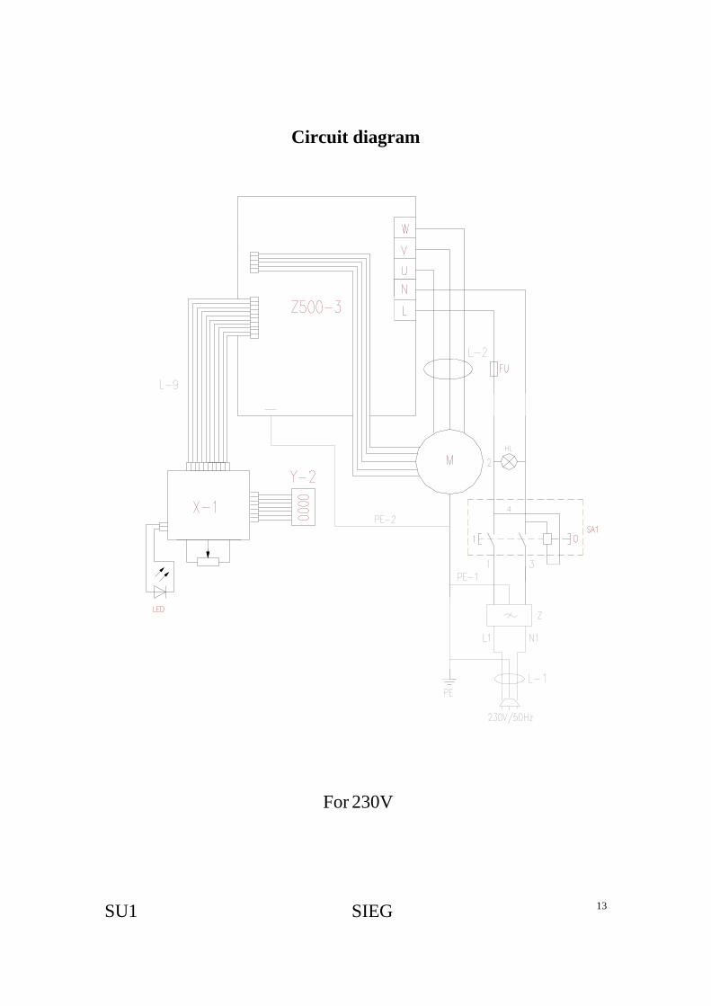
SU1 SIEG 13
Circuit diagram
For 230V

SU1 SIEG 14
For 110V

SU1 15
43 3551
4558 45
3637
49
50 38
52 3148
47 31
41
4639
548
17
1140
31 53
56
34
4457
42
55
2619
15
16
18
12
2827
3130
32
22
256
9
8723
21
23
3329
12
2024
10
15
14
6
9
5
4
87
94
91
93
9264
10385
102103
1596
82
11128
83
77
93
61
6374
75
9597
2812
99
9815
9728
1
2
3
84
79
73
42
101
72
71
91
60
105
104
62
86
6768
6515
16
9168
69
87
70
9088
89
80
86
8176
10069
87
7090
8889
80
10978
10668107108
6811070
80
908889
66
100121
141
128
140
125120
91
5 134 132124
139
126
116
130
118113
11959
138
115
123
59
137
135131
122
133
117
129
127
112
114
136
142
143
13
Exploded drawing of parts

SU1 SIEG 17
Part detail list No. Part number Name Quantity1 U12303 Dust guard 1
2 U12302 Fixing plate 1
3 GB 818-85 - M6 x 8 Cross recessed small pan head screw 4
4 U12301 Shield 1
5 GB 818-85 - M4 x 8 Cross recessed small pan head screw 6
6 U10203 Lock sleeve 2
7 GB 70-85 - M6 x 25 Hexagon socket head screw 2
8 GB 97.1-85 - 6 Washer 6
9 GB 70-85 - M6 x 16 Hexagon socket head screw 2
10 U10201 Spindle box 1
11 U10204 Latch segmentⅠ 1
12 X20218B01 Little handle 5
13 GB5781-86 M6x50 Locking screw 1
14 U10206 Scale of degrees 1
15 GB827-86 2x4 Rivet for name plate 12
16 X21118 Indicator 3
17 U10207 Latch segmentⅡ 1
18 U10901A Upright post 1
19 U10902 Ram 1
20 U10904 Junction block of horizontal milling bed 1
21 60∮ Blade milling cutter 1
22 GB 97.1-85 - 10 washer 3
23 U20231 Adjusting washer(Ⅱ) 6
24 U20229 Bronze bushing 1
25 U10903A Spindle of horizontal milling bed 1
26 U10905 Ram gag 1
27 GB 79-85 - M6 x 30 Slotted headless set screw 2
28 GB 6172-86 - M6 Hexagon nut 12
29 U10906 Junction block gag 1
30 U10907 Cover 1
31 GB 818-85 - M3 x 6 Cross recessed small pan head screw 15
32 GB 5781-86 - M10x25 Hexagon screw 3
33 GB 6170-86 - M14 Hexagon nut 1
34 GB 301-84 - 8107 Thrust ball bearing 1
35 GB 301-84 - 8106 Thrust ball bearing 1
36 GB 810-88 - M27x1.5 Slotted round nut 2

SU1 SIEG 18
No. Part number Name Quantity 37 GB 894.1 - 25 Circlip 1
38 GB 810-88 - M20x1.5 Slotted round nut 2
39 GB 70-85 - M8 x 25 Hexagon socket head screw 1
40 U10202B02 Permanent-magnet direct current motor 1
41 GB1096-79 3x16 Synchronous pulley of motor 1
42 GB1096-79 5x10 Parallel key 3
43 U10202B01 Parallel key 1
44 U20202 Pulley box 1
45 U20205 Washer(Ⅰ) 2
46 U20233 Washer(Ⅱ) 1
47 U20208 Gearbox bracket 1
48 U10202A02 Dust guard 1
49 U1020204 Synchronous pulley of spindle 1
50 1.5x100x9 Jugged synchronous belt 1
51 GB1096-79 4x12 Parallel key 3
52 U1020207 Top cover 1
53 U1020208 Bottom cover 1
54 GB 5781-86 - M6x20 Hexagon headed bolt 4
55 U10202A01 R8 Spindle 1
56 U1020202 Spindle socket 1
57 GB 278-89 - 1080907 Ditch ball bearing 2
58 GB 279-89 - 180106 Ditch ball bearing 1
59 GB 846-85 - ST2.9 x 9.5 Tapping screw (for sheet metal) 8
60 U11101 Base 1
61 U11102 Lift 1
62 X211C02 Worktable 1
63 X211C01 Vertical gag 1
64 X21109 Metric vertical screw nut 1
65 X211C08 Bearing base 1
66 X211C06 Left cover 1
67 X211C09 Metric vertical screw 1
68 GB 301-84 - 8200 Thrust ball bearing 4
69 X21111 Metric dial 2
70 X21117B Hand wheel 3
71 U11105 Nut base 1
72 U11109 Metric lifting nut 1
73 U11110 Metric lifting screw 1
74 U11103 Saddle 1
75 X211C05 Horizontal gag 1

SU1 SIEG 19
No. Part number Name Quantity 76 X21115 Horizontal screw base 1
77 X21113 Metric horizontal screw nut 1
78 U11111 Little cone gear 1
79 U11112 Big cone gear 1
80 GB 889-86 - M8 Hexagon locking nut 3
81 U11104 Metric horizontal screw 1
82 U11108 Gag 1
83 GB 5781-86 - M8x25 Hexagon headed bolt 3
84 GB 301-84 - 8202 Thrust ball bearing 1
85 U11113 Cover 1
86 GB1096-79 4x16 Parallel key 3
87 X20221 Damping spring 3
88 C2A0307 Handle 3
89 GB 65-85 - M8 x 55 Slotted circular headed screw 3
90 GB 6172-86 - M8 Hexagon nut 3
91 GB 70-85 - M6 x 14 Hexagon socket head screw 11
92 X31131 Vertical screw bracket left socket 1
93 JB/T7940.4-95 6 Pressed-on forced filling oil cup 2
94 X31136 Left bracket cover 1
95 GB 77-85 - M6 x 10 Hexagon set screw 2
96 X21103 Metric ruler 1
97 GB 79-85 M6 x 22 Hexagon set screw 8
98 C5C0315 Zero label 1
99 GB 70-85 - M6 x 30 Hexagon socket head screw 1
100 GB 70-85 - M6 x 10 Hexagon socket head screw 3
101 GB 77-85 - M5 x 8 Hexagon set screw 2
102 U11114 Locking nut 1
103 GB 819-85 - M3x6 Cross slot sunk screw 5
104 X31101 Footing adjusting screw 4
105 GB 6172-86 - M12 Hexagon nut 4
106 U11106 Lifting axis 1
107 U11107 Bearing base 1
108 GB 70-85 - M4 x 14 Hexagon socket head screw 3
109 GB 71-85 - M5 x 8 Slotted set screw with cone point 2
110 U11115 Metric dial 1
111 GB 79-85 - M6 x 16 Slotted headless set screw 2
112 M14 Light base 1
113 Magnetic switch 1
114 Green light 1
SU1 SIEG 20
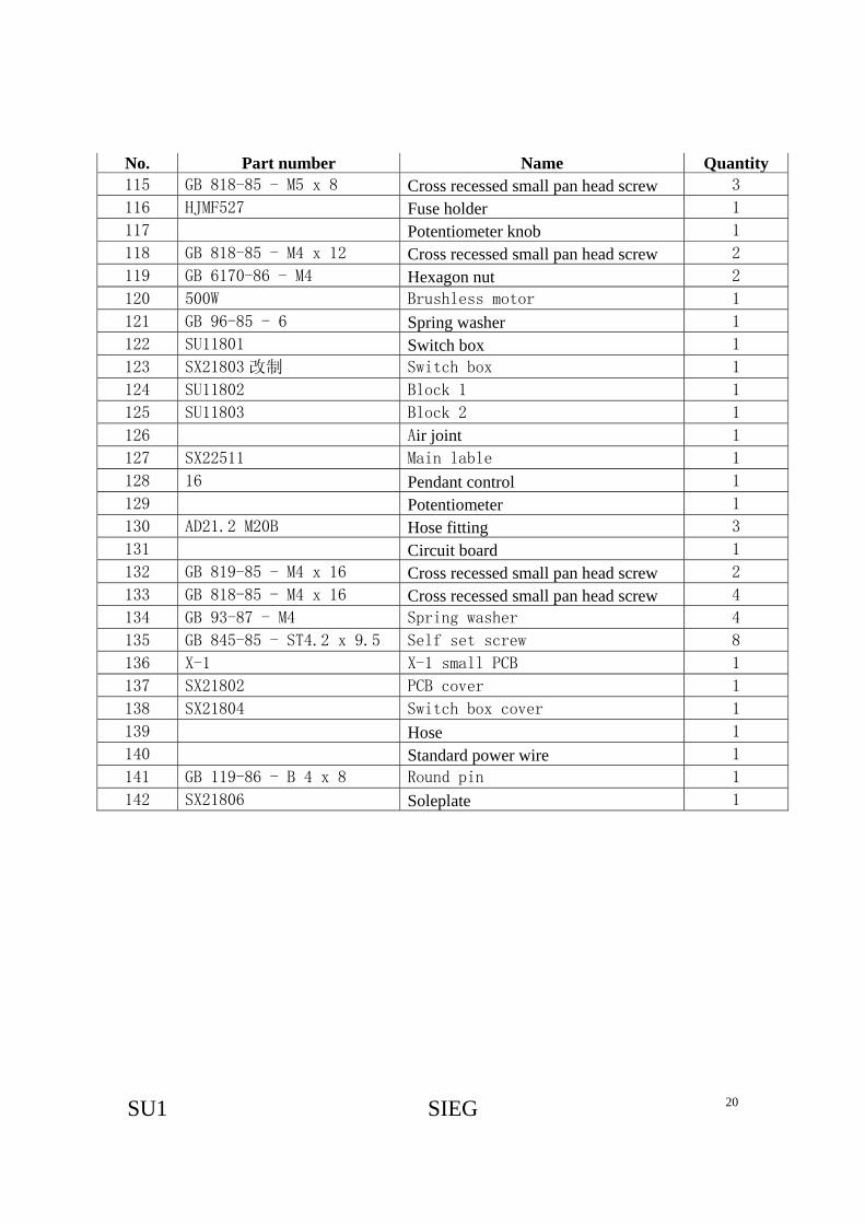
No. Part number Name Quantity 115 GB 818-85 - M5 x 8 Cross recessed small pan head screw 3
116 HJMF527 Fuse holder 1
117 Potentiometer knob 1
118 GB 818-85 - M4 x 12 Cross recessed small pan head screw 2
119 GB 6170-86 - M4 Hexagon nut 2
120 500W Brushless motor 1
121 GB 96-85 - 6 Spring washer 1
122 SU11801 Switch box 1
123 SX21803 改制 Switch box 1
124 SU11802 Block 1 1
125 SU11803 Block 2 1
126 Air joint 1
127 SX22511 Main lable 1
128 16 Pendant control 1
129 Potentiometer 1
130 AD21.2 M20B Hose fitting 3
131 Circuit board 1
132 GB 819-85 - M4 x 16 Cross recessed small pan head screw 2
133 GB 818-85 - M4 x 16 Cross recessed small pan head screw 4
134 GB 93-87 - M4 Spring washer 4
135 GB 845-85 - ST4.2 x 9.5 Self set screw 8
136 X-1 X-1 small PCB 1
137 SX21802 PCB cover 1
138 SX21804 Switch box cover 1
139 Hose 1
140 Standard power wire 1
141 GB 119-86 - B 4 x 8 Round pin 1
142 SX21806 Soleplate 1


![Machine Control for Milling and Paving REVA [Read-Only]...VariableDepth 3D Milling ‐Mill complex designs Variable depth and slope milling enables milling of: – Transitions –](https://static.documents.pub/doc/80x56/5e8e34680eeb4f7248583c60/machine-control-for-milling-and-paving-reva-read-only-variabledepth-3d-milling.jpg)


![5. MILLING MACHINE - gptcadoor.orggptcadoor.org/assets/downloads/npestgdiuk430mp.pdf[Machine Tools – Milling Machine] Page 1 5. MILLING MACHINE ... Table type milling machine 3.](https://static.documents.pub/doc/80x56/5e4d2efc0c5fe27c0b327453/5-milling-machine-machine-tools-a-milling-machine-page-1-5-milling-machine.jpg)


