This article was downloaded by: [79.110.128.31] On: 19 July 2014, At: 20:08 Publisher: Taylor & Francis Informa Ltd Registered in England and Wales Registered Number: 1072954 Registered office: Mortimer House, 37-41 Mortimer Street, London W1T 3JH, UK Enterprise Information Systems Publication details, including instructions for authors and subscription information: http://www.tandfonline.com/loi/teis20 Modelling and analysis of workflow for lean supply chains Jinping Ma a b , Kanliang Wang c & Lida Xu d a School of Management, Xi'an Jiaotong University , Xian, 710049, China b Department of Management Science and Engineering , Qingdao University , Qingdao, 266071, China c Department of Management Science and Engineering , Renmin University of China , Beijing, 100872, China d Department of Information Technology and Decision Science , Old Dominion University , Norfolk, VA, 23529, USA Published online: 24 Jun 2011. To cite this article: Jinping Ma , Kanliang Wang & Lida Xu (2011) Modelling and analysis of workflow for lean supply chains, Enterprise Information Systems, 5:4, 423-447, DOI: 10.1080/17517575.2011.580007 To link to this article: http://dx.doi.org/10.1080/17517575.2011.580007 PLEASE SCROLL DOWN FOR ARTICLE Taylor & Francis makes every effort to ensure the accuracy of all the information (the “Content”) contained in the publications on our platform. However, Taylor & Francis, our agents, and our licensors make no representations or warranties whatsoever as to the accuracy, completeness, or suitability for any purpose of the Content. Any opinions and views expressed in this publication are the opinions and views of the authors, and are not the views of or endorsed by Taylor & Francis. The accuracy of the Content should not be relied upon and should be independently verified with primary sources of information. Taylor and Francis shall not be liable for any losses, actions, claims, proceedings, demands, costs, expenses, damages, and other liabilities whatsoever or howsoever caused arising directly or indirectly in connection with, in relation to or arising out of the use of the Content. This article may be used for research, teaching, and private study purposes. Any substantial or systematic reproduction, redistribution, reselling, loan, sub-licensing, systematic supply, or distribution in any form to anyone is expressly forbidden. Terms &
Transcript
This article was downloaded by: [79.110.128.31]On: 19 July 2014, At: 20:08Publisher: Taylor & FrancisInforma Ltd Registered in England and Wales Registered Number: 1072954 Registeredoffice: Mortimer House, 37-41 Mortimer Street, London W1T 3JH, UK
Enterprise Information SystemsPublication details, including instructions for authors andsubscription information:http://www.tandfonline.com/loi/teis20
Modelling and analysis of workflow forlean supply chainsJinping Ma a b , Kanliang Wang c & Lida Xu da School of Management, Xi'an Jiaotong University , Xian, 710049,Chinab Department of Management Science and Engineering , QingdaoUniversity , Qingdao, 266071, Chinac Department of Management Science and Engineering , RenminUniversity of China , Beijing, 100872, Chinad Department of Information Technology and Decision Science ,Old Dominion University , Norfolk, VA, 23529, USAPublished online: 24 Jun 2011.
To cite this article: Jinping Ma , Kanliang Wang & Lida Xu (2011) Modelling and analysisof workflow for lean supply chains, Enterprise Information Systems, 5:4, 423-447, DOI:10.1080/17517575.2011.580007
To link to this article: http://dx.doi.org/10.1080/17517575.2011.580007
PLEASE SCROLL DOWN FOR ARTICLE
Taylor & Francis makes every effort to ensure the accuracy of all the information (the“Content”) contained in the publications on our platform. However, Taylor & Francis,our agents, and our licensors make no representations or warranties whatsoever as tothe accuracy, completeness, or suitability for any purpose of the Content. Any opinionsand views expressed in this publication are the opinions and views of the authors,and are not the views of or endorsed by Taylor & Francis. The accuracy of the Contentshould not be relied upon and should be independently verified with primary sourcesof information. Taylor and Francis shall not be liable for any losses, actions, claims,proceedings, demands, costs, expenses, damages, and other liabilities whatsoever orhowsoever caused arising directly or indirectly in connection with, in relation to or arisingout of the use of the Content.
This article may be used for research, teaching, and private study purposes. Anysubstantial or systematic reproduction, redistribution, reselling, loan, sub-licensing,systematic supply, or distribution in any form to anyone is expressly forbidden. Terms &
Modelling and analysis of workflow for lean supply chains
Jinping Maa,b*, Kanliang Wangc and Lida Xud
aSchool of Management, Xi’an Jiaotong University, Xian 710049, China; bDepartment ofManagement Science and Engineering, Qingdao University, Qingdao 266071, China;
cDepartment of Management Science and Engineering, Renmin University of China, Beijing100872, China; dDepartment of Information Technology and Decision Science, Old Dominion
University, Norfolk, VA 23529, USA
(Received 12 April 2010; final version received 7 April 2011)
Cross-organisational workflow systems are a component of enterprise informa-tion systems which support collaborative business process among organisations insupply chain. Currently, the majority of workflow systems is developed inperspectives of information modelling without considering actual requirements ofsupply chain management. In this article, we focus on the modelling and analysisof the cross-organisational workflow systems in the context of lean supply chain(LSC) using Petri nets. First, the article describes the assumed conditions of cross-organisation workflow net according to the idea of LSC and then discusses thestandardisation of collaborating business process between organisations in thecontext of LSC. Second, the concept of labelled time Petri nets (LTPNs) is definedthrough combining labelled Petri nets with time Petri nets, and the concept oflabelled time workflow nets (LTWNs) is also defined based on LTPNs. Cross-organisational labelled time workflow nets (CLTWNs) is then defined based onLTWNs. Third, the article proposes the notion of OR-silent CLTWNS and averifying approach to the soundness of LTWNs and CLTWNs. Finally, thisarticle illustrates how to use the proposed method by a simple example. Thepurpose of this research is to establish a formal method of modelling and analysisof workflow systems for LSC. This study initiates a new perspective of researchon cross-organisational workflow management and promotes operation manage-ment of LSC in real world settings.
Keywords: Petri nets; labelled time workflow nets; labelled time Petri nets; leansupply chain; enterprise information systems modelling; enterprise informationsystems; information modelling; SCM
1. Introduction
In order to promote the competitive advantage of supply chain management,features such as leanness, agility and leagility are considered important (Naylor et al.1999, Mason-jones et al. 2000, Stratton and Warburton 2003, Li 2007, Li andWarfield 2011, Xu 2011). The key idea is to emphasise the collaborative businessprocess between organisations. Such ideas are also good for cross-organisationalcollaboration. Workflow systems are developed to support the operation of supply
chains, especially they are to be tightly integrated (Basu and Kumar 2002). Cross-organisational workflow systems are a component of enterprise information systemswhich support cross-organisational collaboration (Xu et al. 2009). Modelling andanalysis methods of cross-organisational workflows are the key issue of developingsuch workflow systems. Currently, the majority of workflow systems are onlydeveloped from IT perspectives without considering actual requirement of supplychain management. The gap between modelling of workflows and above-mentionedcharacteristics is substantial. Although modelling and analysis of workflow systemsin supply chain environment has been addressed by existing literature (Fung et al.2003, Liu et al. 2005), to the best of our knowledge, little efforts have been made tomodel workflows with respect to leanness and agility as well as leagility of supplychains.
In this article, we focus our work on the modelling and analysis of cross-organisational workflow in context of lean supply chain (LSC). The purpose of thestudy is to establish a formal method of modelling and analysis of workflow systemsfor LSCs. The study is of great significance to initiate a new perspective of researchon cross-organisational workflow management. In addition, the study is also of somesignificance for expanding the scope of workflow systems and promoting the idea ofLSC as well as the operation of LSC.
The remaining sections of this article will be organised as follows. In Section 2,the basic definition related to Petri net and workflow net, and reviews of cross-organisation workflow are presented. In Section 3, characteristics of LSC aredescribed and research assumptions are defined according to the characteristics ofLSCs, and standardisation of collaborating business process between organisationsis defined. In Section 4, modelling and analysis of cross-organisational workflows isintroduced which is the main work completed in this study. In Section 5, exampleson LSC are described by using the result of Section 4. The last section of the articlewill include conclusions and future research.
2. Preliminaries and related works
2.1. Petri nets
Petri nets are a class of modelling tools, which were originated by Petri (Quartel et al.2009, Du et al. 2011). Petri nets are based on a strong mathematical formalism andan easy-to-understand graphical feature, which makes it possible to set upmathematical models describing the behaviour of the system. Moreover, modelvalidation can be achieved using Petri nets techniques. Petri nets are specially suitedfor modelling and analysis of discrete event dynamic systems (Hruz and Zhou 2007).Petri nets are one of the main methods of modelling and analysis of workflowsystems (Salimifard and Wright 2001). The following definitions are about a Petri netas well as its basic properties (Murata 1989).
Definition 2.1. A Petri net is a 4-tuple PN ¼ (P, T; F, M0), where
(1) P ¼ {pi:i ¼ 1, . . . ,jPj} is a finite set of places;(2) T ¼ {tj:j ¼ 1, . . . ,jTj} is a finite set of transitions, T \ P ¼ Ø;(3) F � (P6T) [ (T6P) is a set of directed arcs representing flow relation;(4) M0:p!{0,1,2, . . . } is the marking of initial state. The value of M(p) is also
said to be the number of tokens placed in p in the marking M.(5) W:F!{1} is a weighted function, i.e., weight on edge is 1.
424 J. Ma et al.
Dow
nloa
ded
by [
79.1
10.1
28.3
1] a
t 20:
08 1
9 Ju
ly 2
014
For any node x 2 T [ P, .x ¼ {yj(y,x) 2 F are called the preset of node x, andx. ¼ {yj(x,y) 2 F are called the post-set of node x. A transition t is said to be enabledat M if 8p 2 .t:M(p) 4 0. It’s firing results in new marking M0, where
M0ðpÞ ¼MðpÞ þ 1 if p 2 t��� tMðpÞ � 1 if p 2 �t� t�
MðpÞ otherwise
8<:
R(M0) is used to denote the set of all reachable markings from M0.Definition 2.2. Petri Net PN ¼ (P, T; F, M0) is said to be k-bounded (k 4 0), if
8p 2 P, 8M 2 R(M0):M(p) � k. P is safe, if k ¼ 1.Definition 2.3. Petri Net PN ¼ (P, T; F, M0) is live, if 8M 2 R(M0),8t 2 T, there
is a M0 2 R(M), which makes M0[t 4.Definition 2.4. A Petri net is strongly connected if, for every pair of nodes (i.e.
places and transitions) x and y, there is a path leading from x to y.A labelled Petri net (LPN) was defined in (Du et al. 2009a,b). In an LPN, places
include that token are called control tokens, and tokens control the progress of theLPN together with the exchanged messages from local LPNs to other LPNs via thenetwork. All the exchanged messages among LPNs are recorded after starting a newcase in workflow systems. In an LPN, transitions are classified into three types: In,Out and Inner transitions. In transitions denote the activities of receiving a messagefrom a partner; Out transitions denote the activities of sending a message to apartner; and Inner ones contain all inner activities in the LPN. The definition ofLPN is as follows (Du et al. 2009b):
Definition 2.5. A labelled Petri net is a 7-tuple LPN ¼ (P, T, F, M0, C, S,LF)where
(1) (P, T, F, M0) is a Petri net, where T ¼ Tin [ Tout [ Tinn, and Tin, Tout andTinn are mutually exclusive sub-sets of In, Out and Inner transitions,respectively;
(2) M: P!{0, 1} is a marking function, and M0 denotes the initial marking;(3) W: F!{1} is a weighted function, i.e., weight on edge is 1.(4) C is a set of the messages exchanged between LPNs via the network, and
each message in C is of the form [(Msg, S, R)], where Msg is the messagename, S is the sender, and R is the receiver of the message; (M, C) denotes astate of LPN, and (M0, C0) is an initial state where C0 ¼ Ø; C is a record ofall the exchanged messages among LPNs after a cooperation starts. C isemptied once a new case starts, and all recorded messages are alwaysavailable within the life cycle of a case.
(5) S is a finite set of activity labels, i.e., an alphabet;(6) LF:T!S is a label function;(7) 8t 2 T, t is enabled at (M, C) iff t 2 Tout [ Tinn 8p 2 .t: M(p) ¼ 1; or
t 2 Tin: LF(t) ¼ In (Msg, S, R), 8p 2 .t: M(p) ¼ 1 and 9[(Msg, S, R)] 2 C;(8) 8t 2 T, if t is enabled at (M, C), it may fire and firing it generates a new state
(M0, C0). M0 is the same as (4) in Definition 2.1; if LF(t) ¼ Out(Msg, S, R),C0 ¼ C [ {[(Msg, S, R)]}, and otherwise, C0 ¼ C.
The definition of a time Petri net (TPN, for short) (Penczek 2006, Du et al. 2007)is as follows.
Enterprise Information Systems 425
Dow
nloa
ded
by [
79.1
10.1
28.3
1] a
t 20:
08 1
9 Ju
ly 2
014
Definition 2.6. A time Petri net is a 6-tuple TPN ¼ (P, T, F, M0, REFt, RLFt),where
(1) (P, T, F, M0) is a Petri net;(2) REFT: T!IN, RLFT: T ! IN [ {?} are functions describing the relative
earliest firing time and the relative latest firing time of the transitionsrespectively, where clearly REFT(t) � RLFT(t) for each t 2 T. IN is the setof naturals (including 0).
(3) If a transition t with relative firing domain RD(t) ¼ [REFT(t), RELFT(t)] isenabled at global time Y, it must fire in absolute time domain AD(t) ¼[YþREFT(t), YþRLFT(t)] ¼ [AEFT(t), ALFT(t)], which is called anabsolute firing domain, unless it becomes disabled by the removal of tokenfrom some of its input places.
(4) A triple (M, Y, AD) presents state of a TPN, M is a marking reachable fromM0, Y is the global time when M is reached, AD is a vector containing theabsolute time domain of all transitions enabled at M. A triple (M0, 0, AD0) isthe initial state of a TPN. Let R0(M0, 0, AD0) denote a set of all statesreachable from (M0, 0, AD0) in a TPN.
(5) A transition t becomes enabled in (M1, Y1, AD1) if 8p 2 .t, p contains atleast one token at marking M1. t is firable if t is enable in (M1, Y1, AD1) andif at the current global timeY2, there is AEFT(t) � Y2 � ALFT (t0), where t0
is any other enabled transition, i.e., (M1, Y1, AD1) [(t, Y2) 4 (M2, Y2, AD2).
Definition 2.7. (Language projection). Let X be a finite alphabet, Y � X, �X!Y isa projection mapping from X to Y if for �X!Y:X*!Y*, 8s 2 X*, �X!Y(s)represents the rest part of s by deleting the elements in set X 7 Y. Particularly, forZ � X, �X!Y(Z) denotes the alphabet that consists of the rest elements of Zexcluding the elements in set Z 7 Y.
2.2. Workflow nets
A Petri net which models the control-flow dimension of a workflow, is called aWorkflow net (WF-net). It should be noted that a WF-net specifies the dynamicbehaviour of a single case in isolation (van der Aalst 2004).The definition of a WF-net is as follows:
Definition 2.8. A Petri net PN ¼ (P, T, F, M0) is a WF-net (Workflow net) if
(1) there is one source place i 2 P such that .i ¼ Ø;(2) there is one sink place o 2 P such that o. ¼ Ø;(3) We add a transition t# to PN which connects sink place o with source place i
(i.e., .t# ¼ {o} and t#. ¼ {i}), then the resulting Petri net is strongly connected.
Note that i (o) is used to denote place i(o) and the marking with only one token inplace i(o).
2.3. Related work
A cross-organisational workflow is generally comprised of intra-organisationalworkflows and inter-organisational workflows (IOWFs) (Xu et al. 2009). The
426 J. Ma et al.
Dow
nloa
ded
by [
79.1
10.1
28.3
1] a
t 20:
08 1
9 Ju
ly 2
014
modelling and analysis techniques for the intra-organisational workflows arerelatively matured. Hence, the modelling and analysis techniques for the IOWFsare briefly reviewed with regard to the application of Petri nets in the modellingand analysis of workflows. This is why the Petri nets are not only the main modellingand analysis tool for intra-organisational workflows but also the main modelling andanalysis methodology for IOWFs (Lindert and Deiters 1999, van der Aalst 1999a).
Zisman (1977) developed a Petri net based approach to specification andautomation of office procedures, which is the initial research on workflowmanagement. Subsequently, over the past 20 years a number of researchers haveused Petri nets as workflow representation formalism (Salimifard and Wright 2001).However, the majority of traditional workflow systems assumed one centralisedenactment service and were not able to support IOWFs, but created problems suchas inconsistency and duplication of work due to the lack of transparency in cross-organisation workflow systems (van der Aalst 1999a). Hence, modelling and analysistechniques of cross-organisational workflow systems are new challenges forresearchers.
With respect to modelling and analysis for workflows, a number of papers aboutmodelling and analysis techniques for workflow systems have been published. Forexample, van der Aalst (1999b, 2000b) defined a loosely coupled IOWF net based onPetri nets and message sequence charts (MSC) and discussed its verification andconsistency, and presented a method based on Petri nets (2000a), which exploited thestructure of the Petri net to find potential errors in designing workflows and allowsfor the compositional verification of workflows. Modelling and analysis of IOWFs interm of Petri nets was also proposed which focused on the techniques for verifyingthe correctness of IOWFs (van der Aalst 1998b). One study (van der Aalst 1998b)focused on a loosely coupled workflow process in which two communicationmechanisms interact between organisations: asynchronous and synchronouscommunication. An IOWF based on local workflow nets is also introduced andexpanded. In addition, van der Aalst and Kumar (2003) proposed the techniques ofan eXchangeable Routing Language (XRL) using XML syntax and formalismof Petri nets, which makes it possible for analysing the correctness and performanceof integration described in XRL. Furthermore, Verbeek and Van der Aalst (2004)presented XRL/Woflan which is a software tool using state-of-the-art Petri netanalysis technique for verifying XRL workflows. XRL/Woflan uses eXtensibleStylesheet Language Transformations (XSLT) to transform XRL specifications to aspecific class of Petri nets, and to allow users to design new routing constructs.Hence, In XRL/Woflan, the Petri net representation is used to determine whether theworkflow is correct.
Recently, researchers and practitioners have paid close attention to the issue ofcross-organisational workflow cooperation. Based on the workflow-view approach,Schulz and Orlowska (2004) discussed the entities of an architecture that providesexecution support for mediated and unmediated cross-organisational workflows andargued how this architecture supports workflow view-based cross-organisationalworkflow model. This architecture used a Petri net based representation as the basisfor consideration of state dependencies between the tasks in a workflow and theadjacent task in a workflow view. This representation is focused on the structuralaspects of a workflow, which includes the internal states of tasks and view task, andtheir state dependencies. In order to allow virtual enterprises to collaborativelymanage business processes, Liu and Shen (2003) describes a novel process view
Enterprise Information Systems 427
Dow
nloa
ded
by [
79.1
10.1
28.3
1] a
t 20:
08 1
9 Ju
ly 2
014
which is derived from a base process to provide process abstraction, for modelling avirtual workflow process. This process-view model enhances the conventionalactivity-based process models by providing different participants with various viewsof a process. In context of supply chain, when cooperating with each other,enterprises must closely monitor internal processes and those of partners tostreamline business-to-business (B2B) workflows, the process-view model has beenproposed to extend beyond conventional activity-based process models to designworkflows across multiple enterprises, and presented a process-view-based coordina-tion model for B2B workflow management (Liu and Shen 2004, Tan et al. 2008,2010, Xu et al. 2008a,b, Wu et al. 2009). The proposed approach mitigates theshortcomings of inter-enterprise workflow collaboration. Chebbi and Tata (2005)presented a framework enabling the cooperation of IOWFs. This framework allowsthe plug-in of any existing Workflow Management System (WfMS) able to invokeexternal applications and provide a high degree of flexibility and addresses workflowscooperation requirements. Furthermore, Chebbi et al. (2006) presented the view-basedapproach to dynamic IOWFs cooperation. The relevance of IOWFs is best seen whenconsidering emerging virtual organisational forms. This approach allows for partialvisibility of workflows and their resources, thus providing powerful ways for IOWFconfiguration. Tata et al. (2008) presented a novel bottom-up approach and platformfor workflow interconnection and cooperation in the context of short-term virtualenterprises. To take into the consideration of the privacy of the participants, thepreservation of their pre-established workflows, and the integration of their existingWfMS, they proposed CoopFlow—a new bottom-up approach for the abstraction andadvertisement, matching and interconnection, and cooperation of workflows.
In the above-mentioned literature, important considerations such as time factor,material flow and information flow for LSC collaboration have not been paidattention (Xu 2008, 2009). In the context of LSC, to be efficient, a key issue is tocollaborate business process among its members via cross-organisational WfMS inthe light of requirement information, material flow and capital flow during astipulated time interval. Hence, this article will take occurrence time, material flow,as well as information flow into account while building model of cross-organisational workflow net for LSCs.
Du et al. (2007) proposed an inter-organisational logical workflow net (ILWN)for modelling and analysing real-time cooperative systems (CSs) based on TPNs,workflow techniques and temporal logic. Through attaching logical expressions tosome actions of an ILWN model, the size of the model is reduced. Thus, ILWNs canefficiently mitigate the state explosion problem to some extent. Moreover, withregard to issue such as the existing formal methods for analysing CSs cannotproperly deal with accountability and obligations, Du et al. (2009a) presented a newclass of labelled Petri net (LPN) models. The behaviour of each partner wasrepresented by an LPN, while a CS was modelled by the combination of all partners’LPN models. The obligations were verified based on LPN languages and thenonblocking properties of action sequences, while accountability could be proved bythe network conditions and local action sequences on each partner’s side. Withregard to e-commerce workflows, Du et al. (2009b) introduced labelled workflownets (LWN) and their semantics on the basis of labelled Petri nets, and thenpresented an inter-organisational labelled workflow net (ILWN). Furthermore, theyanalysed the soundness of ILWNs and the undeniable property of interactiveactions. The proposed framework for e-commerce workflows (ECW) is able to
428 J. Ma et al.
Dow
nloa
ded
by [
79.1
10.1
28.3
1] a
t 20:
08 1
9 Ju
ly 2
014
record the history of interactive events and monitor the execution of interactiveactivities to achieve a common goal via recording messages among organisations.
In this article, we will integrate characteristics of labelled Petri nets and those ofTPNs into labelled time Petri nets (LTPNs), define labelled time workflow nets(LTWNs) and cross-organisational LTWNs (CLTWNs) for LSC, and analyse theirproperties by using Petri nets theory.
3. Lean supply chain
In this section, we will introduce the concept of LSC, according to characteristics ofLSC, and will put forward assumed conditions of modelling and analysis of cross-organisation workflow net, and discuss the standardisation of collaborating businessprocess between organisations.
3.1. Lean supply chain
For the last two decades, lean manufacturing that originated from JIT production ofthe Toyota Motor Corporation has been extending from the internal operation ofthe company to supply chain as a whole, which has yielded the concept of LSC. Thedefinition of LSC was discussed in the literature.
Reeve (2002) describes LSC management as ‘planning, executing, and designingacross multiple supply chain partners to deliver products of the right design, in theright quantity, at the right place, at the right time’.
Vitasek et al. (2005) given a more detailed definition of LSC: ‘a lean supply chainas a set of organisations directly linked by upstream and downstream flows ofproducts, services, finances, and information that collaboratively work to reducecost and waste by efficiently pulling what is needed to meet the needs of theindividual customer’.
Rivera et al. (2007) summarised the definition of LSC: ‘a lean supply chain is anetwork of integrated organisations in which the capabilities of all entities arealigned with customer demand. To achieve this status, a lean supply chain mustpossess the following characteristics:
First, close relationships must be established among all supply chain memberswho are sharing gains and responsibilities. A collaboration based on trust is thefoundation for all activities that integrate the supply chain.
Second, information needs to be transparent throughout the supply chain,including the end customer’s demand, opportunities, responsibilities, etc. Therefore,all supply chain members can align themselves with customer demand and aim foroverall benefits.
Third, lean logistics approaches should be implemented to physically carry outand benefit from lean thinking. Finally, to sustain a LSC, performance mustbe monitored, maintained and improved. Metrics that reflect the overall supplychain performance should be adopted, and the results should be visible to allmembers’.
According to Vitasek et al. (2005), supply chain networks are coordinated effortsamong partners to eliminate waste across the supply chain as whole and can beaccomplished only through successful collaboration across common processes.Collaboration among enterprises in supply chains is the foundation that supportsother three building blocks, i.e., lean logistics, information system, performance
Enterprise Information Systems 429
Dow
nloa
ded
by [
79.1
10.1
28.3
1] a
t 20:
08 1
9 Ju
ly 2
014
measurement and continuous improvement. Collaboration facilitates the implemen-tation of lean logistics, information system integration among organisations, andinter-organisational performance measurement systems.
Therefore, in this article, we will construct a model of workflow to reflect theabove-mentioned characteristics of LSC, i.e., model of workflow that can portray thematerial flow, information flow and capital flow using formal methods.
3.2. Assumptions
To meet the requirements of the users for products and services, collaborativemanagement of LSC makes material flow, information flow and capital flow moveamong organisations during the assigned time intervals and at the minimal cost.
According to characteristics of LSC and for the convenience of modelling andanalysis of workflows, we make assumptions as follows:
(1) The requirements of the user are relatively stable and predictable, andtherefore facilitate the level schedule requirements necessary for a LSC.
(2) Upstream enterprises regard meeting production requirement of downstreamenterprises as their goals. Only upstream enterprises reach theirs target, andthen downstream enterprises reach theirs.
(3) Information flow is transmitted downstream to upstream or upstream todownstream, materials are delivered from upstream to downstream, andcapital is transferred from downstream to upstream.
(4) Business processes between upstream enterprise and downstream enterpriseare collaboratively executed via material flow, i.e., execution time of businessprocesses between organisations is coordinative such that upstreamenterprise can deliver materials for downstream enterprise in accordancewith time and quantity of delivering materials required by downstreamenterprise.
(5) Business processes between upstream enterprise and downstream enterpriseare collaboratively executed via information flow and capital flow inaccordance with time of collaboration between enterprises.
3.3. Standardisation of collaborating business process between organisations
With regard to stable LSC system, processes of collaborating business processbetween organisations ought to be standardised. Bala and Venkatesh (2007) definedinter-organisational business process standards (IBPS) as ‘technical specifications forinterrelated, sequential tasks and business documents that are agreed upon andshared by trading entities to achieve a defined and common business objective. IBPSare designed and developed to automate, integrate, and facilitate value chainactivities such as supply chain management, collaborative forecasting, new productdevelopment, and inventory management’, ‘IBPS are semantic standards that notonly specify and define the structure and format of business messages through acommon language but also orchestrate the message exchange choreography, i.e.,sequence of steps required to execute an atomic business process among tradingpartners’.
Therefore, processes of collaborating business process between organisations area series of sequence processes which are arranged by means of contracts between
430 J. Ma et al.
Dow
nloa
ded
by [
79.1
10.1
28.3
1] a
t 20:
08 1
9 Ju
ly 2
014
organisations. In general, in a case we assume what process of collaborating businessprocess is as follows:
Step 1: Downstream enterprise sends requirement information to its upstreampartners (suppliers or third logistics);Step 2: After receivingdemand information fromdownstream enterprise, supplierought to send information of confirmation to theirs downstream enterprise;Step 3: After manufacturing purchasing materials, supplier delivers materials todownstream enterprise on time;Step 4: After receiving materials from upstream supplier, downstream enterprise(e.g., manufacturer or customer) pays for materials.
In above steps of collaboration business process, collaborative processes mustmeet assumptions in 3.2.
In reality, other processes of collaborating business process between organisa-tions are added to above steps, in which cross among steps must not be allowed. Forexample, before receiving demand information, supplier cannot send information ofconfirmation and cannot deliver materials for downstream enterprise; beforeobtaining materials, downstream enterprise cannot pay for components etc.Otherwise, cross among above steps be known as non-standardisation ofcollaborating business process among organisations. In Section 4.3, we will provethat non-standardisation of collaborating business process among organisationsgenerate deadlock of cross-organisational workflow nets, which causes non-soundness of cross-organisational workflow nets.
4. Modelling and analysis of cross-organisational workflow
In this section, we will combine LPNs with TPNs, and define LTPNs. Based onLTPNs, LTWNs and CLTWNs will be defined. Flaws in the design of a workflowdefinition may also lead to longer throughput time, low service level and a need forexcess capacity (Basu and Kumar 2002). Therefore, it is important to analyse aworkflow process definition before it is put into production, i.e., soundness ofLTWNs and CLTWNs will be verified via theoretical analysis.
4.1. Labelled time petri nets
Definition 4.1 LTPNs is a 8-tuples LTPNs ¼ (P,T,F,M0,C0,REFT, RLFT, S,LF),where
(1) (P, T, F) is an PN, P ¼ PC [ PD, where PC is a set of the control places,which stores the control marking that controls whether transition becomeenabled. 8t 2 T,.t and t. includes one control place at least. PD is a set of thedata places, PD ¼ Pinf
D [ PcapD [ Pmat
D , PinfD is a set of the information data
places, PcapD is a set of the capital data places, Pmat
D is a set of the material dataplaces. A data place pd stores a data object, which is IOWF data that .Pd
generated. Tokens in Pd are called control conditions of inter-organisationalcollaboration, which controls whether transitions of inter-organisationalinterfaces enabled. Each place in P contains only one control token or noneat any moment.
Enterprise Information Systems 431
Dow
nloa
ded
by [
79.1
10.1
28.3
1] a
t 20:
08 1
9 Ju
ly 2
014
(2) T ¼ Tinfin [ Tcap
in [ Tmatin [ Tinf
out [ Tcapout [ Tmat
out [ Tinn, where Tinfin sub-set of tran-
sitions denotes the actions of receiving a message of information flow fromthe partners in LSC; Tcap
in sub-set of transitions denotes the actions ofreceiving a message of capital flow from the downstream company toupstream company in LSC; Tmat
in sub-set of transitions denotes the actions ofreceiving a message of material (products/services) flow from the upstreamcompany to downstream company in LSC; Tinf
out sub-set of transitions denotesthe actions of sending a message of information flow to the partners in LSC;Tcapout sub-set of transitions denotes the actions of sending a message of capital
flow to its upstream partners in LSC; Tmatout sub-set of transitions denotes the
actions of sending a message of material flow to its downstream partners inLSC. Tinn sub-set of transitions denotes events of internal organisation,which contains all inner actions within each organisation.
(3) M: P!{0, 1} is a marking function, and M0 denotes the initial marking.(4) W:F!{1} is a weighted function, i.e., weight on edge is 1.(5) C is a set of the messages exchanged between LTPNs of organisations in LSC
via the network, and each message inC is of the form [In[typename]jout[typename]
(Msg, S, R)], where Msg is the message’s name, S is the sender of the message,and R is the receiver of the message, where C0 ¼ Ø; for instance, sending anorder message is represented as Outinf(Order, E1, E2), where E1 denotesenterprise 1 and E2 denotes enterprise 2, receiving this order message isrepresented as Ininf(Order, E1, E2).
(6) REFT: T!IN, RLFT: T !IN [ {?} are functions describing the relativeearliest and the relative latest firing times of the transitions, respectively,where clearly REFT(t) � RLFT(t) for each t 2 T. where IN is the set ofnaturals (including 0). In context of LSC, relative earliest firing time and therelative latest firing time of the transitions are firing domains of enabledtransitions. The definition of REFT and RLFT differs on transitions withdifferent labelled types. In accordance with assumptions 3.2 (4)–(5), themeanings of REFT and RLFT are as follows:
REFT and RLFT of tinfout transitions are shortest delay time and longestdelay time of sending information to partners, respectively, after � tinfout
� �� �c
have obtained token. The REFT and the RLFT of tinfin transitions are shortestwaiting time and longest waiting time of receiving information from partners,respectively, after � tinfin
� �� �chave obtained token. The REFT and the RLFT
of tmatout transitions are shortest delay time and longest delay time of delivering
materials to partners, respectively, after � tmatout
� �� �chave obtained token. The
REFT and the RLFT of tmatin transitions are shortest waiting time and longest
waiting time of receiving materials from partners, respectively, after� tmat
in
� �� �chave obtained token. The REFT and the RLFT of tcapin transitions
are shortest waiting time and longest waiting time of receiving payment forproductions from partners, respectively, after � tcapin
� �� �chave obtained token.
The REFT and the RLFT of Tinn transitions are shortest finish timeand longest finish time of business process (or a task). Hence, 8t 62 Tinn, theREFT and the RLFT of transitions are time windows of collaboratingbusiness process among organisations.
(7) S is a finite set of activity labels, i.e., an alphabet.(8) LF:T!S is a label function. 8t 2 Tinn; LFðtÞ ¼ si; 8t =2 Tinn;LFðtÞ ¼½In½typename�jOut½typename�; ðMsg;R; SÞ�.
432 J. Ma et al.
Dow
nloa
ded
by [
79.1
10.1
28.3
1] a
t 20:
08 1
9 Ju
ly 2
014
(9) The transition firing rules: In LPNs, a state of LPNs is determined by (M, C).In TPNs,a state of TPNs is determined by (M, Y, AD). Therefore, a state ofLTPNs is determined by (M, Y, C, AD). In LPNs, the firing time domains ofa message is without limits, and in LTPNs, the firing time domains of amessage is limited to a fixed scope, the firing time domain is determined by(Y, AD). Where Y represent global time at reachable marking M, AD is avector containing the absolute firing domains of all transitions enabled atreachable making M. Hence, firing regulations of transitions is derived byDefinition 2.5 and Definition 2.6 as follows.(a) 8t 2 Tinf
out [ Tcapout [ Tmat
out [ Tinn, t becomes enable in (M1, Y1, C1, AD1) if8pc 2 �t : M1ðpcÞ ¼ 1; 8t 2 Tinf
in [ Tcapin [ Tmat
in , t becomes enable in (M1,Y1, C1, AD1) if 8pc 2 �t ^ 8pd 2 �t : M1ðpcÞ ¼1 ^M1ðpdÞ ¼ 1 ^ 9 ½In½inf jcapjmat� ðMsg; S;RÞ� 2 C1.
(b) If transition t is enable in (M1, Y1, C1, AD1) and if AEFT(t) � Y2
ALFT(t0), then t fires in (M1, Y1, C1, AD1), Where t0 is any otherenabled transition. When t fires at time Y2 in (M1, Y1, C1, AD1), thecurrent state (M1, Y1, C1, AD1) changes to the next one (M2, Y2, C2,AD2), which is denoted by (M1, Y1, C1, AD1) [(t, Y2) 4 (M2, Y2, C2,AD2).
M2ðpÞ ¼M1ðpÞ þ 1 if p 2 t� �� tM1ðpÞ � 1 if p 2 �t� t�
M1ðpÞ otherwise
8<:
Where M2 is a reachable marking from M1, and AD1 is avector containing the absolute firing intervals of all transitions enabledat M1.
(c) if LF(t) ¼ Out[infjcapjmat](Msg, S, R), then C2 ¼ C1 [Out½inf jcapjmat�
ðMsg; S;RÞ, else C2 ¼ C1. i.e., it adds a new message to C2, and itdoes not add a new message to C2 when a transition receives a message.
4.2. Labelled time workflow nets
4.2.1. Formal definition
Definition 4.2. LTWNs ¼ (P,T,F,M0,C0,REFT, RLFT,S,LF), is a LTWNs, if thefollowing hold.
(1) (P,T,F,M0,C0,REFT, RLFT,S,LF) is a LTPNs.(2) There is one source place i 2 Pc such that .i ¼ Ø.(3) There is one sink place o 2 Pc such that .o ¼ Ø.(4) Every node x 2 P [ T is on a path from i to o.(5) If a transition t# is added to the LTWNs that connect place o and
ið�t# ¼ fog and ðt#Þ� ¼ figÞ, then its inner ILTWNs ¼ (IP,IT,IF,IM0,IC0,REFT,RLFT,S,LF) is strongly connected, where IP ¼ PC; IT ¼ T [ ft#Þ;IF � ðIP� ITÞ [ ðIT� IPÞ; IC0 ¼ C0; and IM0 ¼ �p!IPðM0Þ.
According to the above definition, ILTWNs is the rest of the LTWNs containingt# after deleting all data places and the corresponding arcs. A correct run of
Enterprise Information Systems 433
Dow
nloa
ded
by [
79.1
10.1
28.3
1] a
t 20:
08 1
9 Ju
ly 2
014
ILTWNs must guarantee that a control token flows from a source place to a sinkplace, which means that company accomplishing production tasks what itundertakes. Else, if a control token cannot flow from a source place i to a sinkplace o, which means that LTWNs is incorrect. Therefore, soundness (correctness) ofLTWNs must be verified by means of analytical methods.
4.2.2. Soundness analysis of LTWNs
Definition 4.3 An LTWNs is sound if for its ILTWNs following hold.
(1) 8ðIM1;Y1; IC1;AD1Þ 2 RððIM0;Y0; IC0;AD0Þ, 9 firing sequence s, a firingdomain AD2, and global time Y2 such that ðIM1;Y1; IC1;AD1Þ½s > ðIM2;Y2; IC2;AD2Þ; IM2ðOÞ ¼ 1, and 8PC 2 IPC�fog : IM2ðPCÞ ¼ 0.This moment, t# is enabled, and (IM2, Y2, IC2, AD2) [t
# 4 (IM0, Y3, IC0,AD3).
(2) 8t 2 IT;8ðIM1;Y1; IC1;AD1Þ 2RðIM0;Y0; IC0;AD0Þ; 9ðIM2;Y2; IC2;AD2Þ2RðIM0;Y0; IC0;AD0Þ such that (IM2, Y2, IC2, AD2) [t 4, i.e., there is notdeadlock in ILTWNs.
Theorem 1: An LTWNs is sound if its ILTWNs is live and bounded.Proof of theorem 1 is as follows.Proof of sufficiency: because of ILTWNs is live, second condition in Definition
4.3 is satisfied of course.The LTWNs that satisfies the first condition in Definition 4.3 will be verified as
follows. In fact, in initial state (IM0, Y0, IC0, AD0), place i has only a control token,M(i) ¼ 1^8PC 2 IP7{i}:IM0(PC) ¼ 0. 8(IM1, Y1, IC1, AD1) 2 R((IM0, Y0, IC0,AD0), a firing sequence s such that (IM1, Y1, IC1, AD1)[s 4 (IM2, Y2, IC2,AD2)^IM2(o) ¼ 1. Where (IM2, Y2, IC2, AD2) is a state by which transition t# isenabled. 9(IM3, Y3, IC3, AD3) 2 R(IM0, Y0, IC0, AD0)), (IM2, Y2, IC2, AD2)[t# 4 (IM3, Y3, IC3, AD3) ^ IM3 (i) ¼ 1. For moment, if 9PC ¼IP7{i}:IM3(PC) 4 0, then 9t 2 .p, making s fire again, a new token is added top, resulting in ILTWNs being not bound, which contradicts the condition ofTheorem 1. Therefore, 8PC ¼ IP7{i}:IM3(PC) ¼ IM0(PC) ¼ 0^IC3 ¼ IC0, whichstarts a new case, i.e., first condition of definition is satisfied by (IM2, Y2, IC2, AD2)[t# 4 (IM0, Y3, IC0, AD3).
Proof of necessity: we will use proof by contradiction to prove necessity ofTheorem 1. Assume that ILTWNs is not live, according to the definition of livenessof Petri Nets, there are two cases as follows:
Case 1: 9(IM1, Y1, IC1, AD1) 2 R((IM0, Y0, IC0, AD0)), 8t 2 IT, 8 s and timeY3, 8(IM2, Y2, IC2, AD2) 2 R((IM0, Y0, IC0, AD0)) such that (IM1, Y1, IC1,AD1) [s 4 (IM2,Y2, IC2, AD2)! (IM2,Y2, IC2, AD2) [(t,Y3) 4 , i.e. 8 (IM2,Y2, IC2, AD2) 2 R((IM0, Y0, IC0, AD0)), IM2 (O) ¼ 0, which manifests thatsink place cannot be enabled and contradict first condition of Definition 4.3.Case 2: 8(IM1, Y1, IC1, AD1) 2 R ((IM0, Y0, IC0, AD0)), 9t 2 IT, 8a anytranstion sequence s and time Y2, 9(IM2, Y2, IC2, AD2) 2 R((IM1, Y1, IC1,AD1) and time Y3, such that (IM1, Y1, IC1, AD1) [ s 4 (IM2, Y2, IC2, AD2) ^! (IM2, Y2, IC2, AD2) [(t, Y3) 4, which contradicts the first condition ofDefinition 4.3.
434 J. Ma et al.
Dow
nloa
ded
by [
79.1
10.1
28.3
1] a
t 20:
08 1
9 Ju
ly 2
014
Furthermore, if ILTWNs is unbounded, according to the definition of Petri netswith unbounded property, 8k 2 N, 9(IM1, Y1, IC1, AD1) 2 R ((IM0, Y0, IC0,AD0)), and PC 2 IP such that IM1(PC) 4 k, and 9t 2 P. is fired in state (IM1, Y1,IC1, AD1) at least twice. According to definition 4.2, 8k 2 N 9p0c 2 IP \ t#; 9Y1;Y2,such that ðIM1;Y1; IC1;AD1Þ ½ðt;Y1Þðt;Y2Þ > ðIM2;Y2; IC2;AD2Þ ^ IM2ðp
(6) 8 t 2 Ti, LF(t) ¼ LFi(t), i ¼ 1, 2, . . . .., n
In order to analyse dynamic behaviour of CLTWN, we defined dependencerelation among LTWN as follows.
Definition 4.5 Let CLTWN be comprised of LTWN1, . . . , LTWNn, 8i, j 2 N ^i 6¼ j an In transition Inmi (msg1, A, B) of Ti depends on an out transitionOutmj(msg2, C, D) of Tj, denoted Inmi(msg1, A, B) Outmj(msg2, C, D), if there is atleast one pair of transitions such chat msg1 ¼ msg2 ^ A ¼ C ^ B ¼ D ^ mi ¼ mj
for short notation, ti tj. The notation! (ti tj) denotes that ti does not depend on tjand where mi and mj represent message type.
4.3.2. Soundness analysis of CLTWN
In the following, we apply Petri nets theory, which is similar to the work reported byDu et al. (2007) for analysing the soundness of CLTWN.
In fact, it is very difficult to analyse CLTWN with complex structure,which is EXPSPACE hard (Cheng et al. 1995). But, if we confine structureof CLTWN in specific structures to meet requirement for simulatingpractical system, then soundness of the CLTWN can be analysed withinpolynomial time (van der Aalst 1998a). Therefore, in the following, the relatedconcepts are introduced first and then the soundness of the CLTWN isanalysed.
Enterprise Information Systems 435
Dow
nloa
ded
by [
79.1
10.1
28.3
1] a
t 20:
08 1
9 Ju
ly 2
014
As shown in Figure 1 (van der Aalst 2000a), ‘a structural characterisation ofgood workflows ought to balance AND/OR-splits and AND/OR-joins. Clearly, twoparallel flows initiated by an AND-split, should not be joined by an OR-join. Twoalternative flows created via an OR-split, should not be synchronised by an AND-join. An AND-split should be complemented by an AND-join and an OR-splitshould be complemented by an OR-join’.
Definition 4.6 (Well-handled). A LTPN is well-handled, if for any pair of nodes xand y such that one of the nodes is a place and the other a transition and for any pairof elementary paths C1 and C2 leading from x to y, Z(C1) \ Z(C2) ¼ {x,y}, thenC1 ¼ C2. An LTWN is well-structured if LTPN# is well-handled (van der Aalst2000a, Du et al. 2007). Where Z(C) represents the alphabet of a path C.
When we construct LTWN of each organisation, workflow net with well-structured should be constructed in the light of Definition 4.6. Moreover, ifCLTWN12 consists of LTWN1 and LTWN2, transition of sending or receivingmessage is included in any conditional routing construction such as OR-split andOR-join, then these transitions cannot fire, which results in accumulating tokens indata places, and CLTWN12 is unbounded. Therefore, we focus on a class ofCLTWN in which none of the sending and receiving messages is included in any ORconditional routing construction, i.e., transitions in OR-split and OR-join pathsought to be inner transitions of LTWN, an LTWN which meets this condition iscalled as OR-silent.
Definition 4.7: Let LTWN as well-structured, then LTWN as OR-silent. If 8pc1,pc2 2 PC, if there exists two elementary paths C1 and C2 (C1 6¼ C2) leading from pc1to pc2, and 8Z(C1) \ Z(C2) ¼ {pc1,pc2}, then 8t 2 T \ ð�PD [ P�DÞ :t =2 ZðC1Þ [ ZðC2Þ. An CLTWN is OR-silent, if each of its LTWN is OR-silent.
For example, Figure 2 is not OR-silent CLTWN. CLTWN12 consists of twosound LTWNs, LTWN1 and LTWN2. In LTWN1, Transition t13 which receives dataof place Pd2 is on OR-split routing path, for which the condition of Definition 4.7does not hold, then LTWN1 is not a OR-silent LTWN, hence CLTWN12 is also notOR-silent.
In addition, Figure 3 represents non-standardisation for collaborating businessprocess between organisations in sub-section 3.3. In Figure 3, after manufacturerhas received information what supplier sent out, manufacturer pays for goods tothe supplier. Only after supplier receives money, it will send informationregarding accepted order. Non-standardisation in collaborating business processbetween organisations will result in a deadlock in cross-organisation workflownets.
While CLTWN is only OR-silent, CLTWN is not necessary well-structured. Onlywhen CLTWN is OR-silent and meets the condition of assumptions and
Figure 1. Good and bad constructions (van der Aalst 2000a).
436 J. Ma et al.
Dow
nloa
ded
by [
79.1
10.1
28.3
1] a
t 20:
08 1
9 Ju
ly 2
014
standardisation in collaborating business process between organisations as describedin Section 3, CLTWN will be well-structured.
In order to analyse the soundness of CLTWN, a renaming and concurrentdecomposing function d of transitions is defined to represent the actions of sendingand receiving message data between organisations.
Definition 4.8. Let CLTWN12 be comprised of LTWN1 and LTWN2 according toassumptions in 3.2, where LTWN1 is workflow net of upstream enterprise, andLTWN2 is workflow net of downstream enterprise. Symbol k a concurrent operator,and d is a renaming and concurrent decomposing function of T12.
(1) With regard to LTWN1, in the light of third section, definition of d is asfollows:(a) if there is an integer k 2 N such that �t \ ðPinf
D1Þ ¼ fp1; p2 . . . pkg, then
dðtÞ ¼ rinf1 ðp1Þjjrinf1 ðp2Þ . . . rinf1 ðphÞ . . . jjrinf1 ðpkÞ where rinf1 ðphÞ denotes aconcurrent output transition of information data places ph in T1,
Figure 2. A non OR-silent CLTWN12.
Figure 3. Non-standardisation in collaborating business process between organisations.
Enterprise Information Systems 437
Dow
nloa
ded
by [
79.1
10.1
28.3
1] a
t 20:
08 1
9 Ju
ly 2
014
1 � h � k, i.e. transitions for receiving information flow from LTWN2
and labelling Ininf(Msg, S, R);(b) if there is an integer k 2 N such that t� \ ðPinf
D1Þ ¼ fp1; p2 . . . pkg, then
dðtÞ ¼ sinf1 ðp1Þjjsinf1 ðp2Þ . . . sinf1 ðphÞ . . . jjsinf1 ðpkÞ where sinf1 ðphÞ denotes aconcurrent input transition of information data places ph in T1,1 � h � k, i.e. transitions of sending information flow to LTWN2 andlabelling outinf(Msg, S, R);
(c) if there is an integer k 2 N such that t� \ ðPmatD1Þ ¼ fp1; p2 . . . pkg, then
dðtÞ ¼ smat1 ðp1Þjjsmat
1 ðp2Þ . . . smat1 ðphÞ . . . jjsmat
1 ðpkÞ where smat1 ðphÞ denotes
a concurrent input transition of material data places ph in T1,1 � h � k, i.e. transitions of sending material flow to LTWN2 andlabelling outmat(Msg, S, R);
(d) if there is an integer k 2 N such that �t \ ðPcapD1Þ ¼ fp1; p2 . . . pkg, then
dðtÞ ¼ rcap1 ðp1Þjjrcap1 ðp2Þ . . . rcap1 ðphÞ . . . jjrcap1 ðpkÞ where rcap1 ðphÞ denotes a
concurrent output transition of capital data places ph in T1, 1 � h � k,i.e. transitions of receiving capital flow from LTWN2 and labellingIncap(Msg, S, R);
(2) With regard to LTWN2, in terms of third section, definition of d is as follows:(a) if there is an integer k 2 N such that t� \ ðPinf
D2Þ ¼ fp1; p2 . . . pkg, then
dðtÞ ¼ sinf2 ðp1Þjjsinf2 ðp2Þ . . . sinf2 ðphÞ . . . jjsinf2 ðpkÞ where sinf2 ðphÞ denotes aconcurrent input transition of information data places ph in T2,1 � h � k, i.e. transitions of sending information flow to LTWN1 andlabelling outinf(Msg, S, R);
(b) if there is an integer k 2 N such that �t \ ðPinfD2Þ ¼ fp1; p2 . . . pkg, then
dðtÞ ¼ rinf2 ðp1Þjjrinf2 ðp2Þ . . . rinf2 ðphÞ . . . jjrinf2 ðpkÞ where rinf2 ðphÞ denotes aconcurrent output transition of information data places ph in T2,1 � h � k, i.e. transitions of receiving information flow from LTWN1
and labelling Ininf(Msg, S, R);(c) if there is an integer k 2 N such that �t \ ðPmat
D2Þ ¼ fp1; p2 . . . pkg, then
dðtÞ ¼ rmat2 ðp1Þjjrmat
2 ðp2Þ . . . rmat2 ðphÞ . . . jjrmat
2 ðpkÞ where rmat2 ðphÞ denotes
a concurrent output transition of material data places ph in T2,1 � h � k, i.e. transitions of receiving material flow from LTWN1 andlabelling Inmat(Msg, S, R);
(d) if there is an integer k 2 N such that t� \ ðPcapD2Þ ¼ fp1; p2 . . . pkg, then
dðtÞ ¼ scap2 ðp1Þjjscap2 ðp2Þ . . . scap2 ðphÞ . . . jjscap2 ðpkÞ where scap2 ðphÞ denotes a
concurrent input transition of capital data places ph in T2, 1 � h � k,i.e. transitions of sending capital flow to LTWN1and labelling out-cap(Msg, S, R);
Definition 4.9 An CLTWN is 1-sound if each of its LTWN is sound, andCLTWN# is live and bounded.
Theorem 2. Let CLTWN12 be OR-silent and be composed of LTWN1 andLTWN2 according to assumptions in 3.2, where LTWN1 is workflow net ofupstream enterprise, and LTWN2 is workflow net of downstream enterprise.CLTWN12 is 1-sound if any elementary path Cz from iz to oz in LTWNz, z ¼ 1,2,there exist no pair of data place p and q such that:
(1) rinf1 ðpÞ �c1 sinf1 ðqÞ and rinf2 ðqÞ �c2 s
inf2 ðpÞ are simultaneously satisfied;
(2) rinf2 ðpÞ �c2 sinf2 ðqÞ and rinf1 ðqÞ �c1 s
inf1 ðpÞ are simultaneously satisfied;
438 J. Ma et al.
Dow
nloa
ded
by [
79.1
10.1
28.3
1] a
t 20:
08 1
9 Ju
ly 2
014
(3) rcap1 ðpÞ �c1 sinf1 ðqÞ and rinf2 ðqÞ �c2 s
cap2 ðpÞ are simultaneously satisfied;
(4) rinf1 ðpÞ �c1 smat1 ðqÞ and rmat
2 ðqÞ �c2 sinf2 ðpÞ are simultaneously satisfied;
(5) rcap1 ðpÞ �c1 smat1 ðqÞ and rmat
2 ðqÞ �c2 scap2 ðpÞ are simultaneously satisfied;
Proof: For simplicity, we only consider situation of information data flowbetween LTWN1 and LTWN2. With regard to situation of capital data flow andmaterial data flow between LTWN1 and LTWN2, proving is similar to thefollowing procedure; hence, in this article, theirs proving procedure is notcovered.
Since LTWN1 and LTWN2 are sound and OR-silent, therefore, LTWN1 andLTWN2 are live and bounded. 8t 2 T1 \ ð�ðPinf
D1Þ [ ðPinf
D1Þ�Þ and 8t 2 T2 \
ð�ðPinfD2Þ [ ðPinf
D2Þ�Þ are not in OR-conditional routing structures. We need to prove
only that each 8t 2 T1 \ ð�ðPinf1 Þ [ ðPinf
1 Þ�Þ and 8t 2 T2 \ ð�ðPinf
D2Þ [ ðPinf
D2Þ�Þ is live,
and that each P 2 PinfD is bounded in CLTWN#
12.Let CD1
represent �T1[P1!�ðPinfD2Þ[ðPinf
D2Þ�ðC1Þ, let CD2
represent
�T2[P2! ð�ðPinf
D2Þ [ ðPinf
D2Þ�ðC2Þ ZðCD1
Þ 6¼ Ø ^ZðCD2Þ 6¼ Ø. The liveness of each
8t 2 T1 \ ð�ðPinfD1Þ [ ðPinf
D1Þ�Þ and 8t 2 T2 \ ð�ðPinf
D2Þ [ ðPinf
D2Þ�Þ can be proved in terms
of the following four cases.
Case 1: The sending and receiving message of transitions in LTWNi and LTWNj
are only in sequential routing constructions, i.e., ð�ðZðCD1ÞÞ [ ðZðCD1
ÞÞ� \ ð�ðZðCD2ÞÞ[ðZðCD2ÞÞ�Þ ¼ Pinf
D . Based on the conditions of the Theorem 2, there exists no pair ofdata places p and q such that:
(1) rinf1 ðpÞ �c1 sinf1 ðqÞ and rinf2 ðqÞ �c2 s
inf2 ðpÞ are simultaneously satisfied, and (2)
rinf2 ðpÞ �c2 sinf2 ðqÞ and rinf1 ðqÞ �c1 s
inf1 ðpÞ are simultaneously satisfied, i.e., there exists
no global time Y such that LTWN1 waits to receive the message data of p fromLTWN2 at time Y, and LTWN2 waits to receive the message data of q from LTWN1
at time Y. Therefore, each transition in ð�ðZðCD1ÞÞ [ ðZðCD2
ÞÞ�Þ 6¼ Ø is live inCLTWN12.
Case 2: �ðZðCD1Þð Þ [ ðZðCD1
ÞÞ�Þ ¼ PinfD and �ðZðCD2Þð Þ [ ðZðCD2ÞÞ�Þ 6¼ Pinf
D i.e.,transitions of receiving and sending message data are in sequential routingconstructions of LTWN1, however transitions of receiving and sending messagedata are in concurrent routing constructions of LTWN2. Therefore, there are k2elementary paths C
ð1Þ2 ; . . . ;C
ðk2Þ2 leading from i2 to o2 such that [0�h�k2
�ðZ CðhÞD2
� �Þ [ ðZ Ch
D2
� �Þ� ¼ Pinf
D . In a process, 8t 2 Z(CD1) [ Z(CD2), t fires onlyonce. For 1, 2, there exists p 2 Pinf
D , such that r1(p) 2 d(Z(CD1)), then there is h ¼ {0,1, . . . , k2} such that s2ðpÞ 2 dðZðCðhÞD2ÞÞ. Since Cu
D2 and CvD2 (u 6¼ v, 0 � u, v � k2)
concurrently fire at t 2 ZðCuD2Þ \ ZðCv
D2Þ in LTWfN2, since�ðZðCD1
Þð Þ [ ðZðCD1ÞÞ�Þ \
ð�ðZðChD2ÞÞ [ ðZðCh
D2ÞÞ�Þ 6¼ Ø, then CD2 is live as the analysis is similar to that in Case
1 for h from 1 to k2.Case 3: �ðZðCD1
Þð Þ [ ðZðCD2ÞÞ�Þ 6¼ Pinf
D and ð�ðZðCD2ÞÞ [ ðZðCD2ÞÞ�Þ ¼ PinfD . i.e.,
transitions of receiving and sending message data are in concurrent routingconstructions of LTWN1; however, transitions of receiving and sending message dataare in sequential routing constructions of LTWN2. Therefore, there are k1elementary paths C
ð1Þ1 ; . . . ;C
ðk1Þ1 leading from i1 to o1 such that [0�h�k1
�ðZ CðhÞD1
� �Þ [ ðZ Ch
D1
� �Þ� ¼ Pinf
D . In a process, 8t 2 Z(CD1) [ Z(CD1
), t fires onlyonce . For 1, 2, there exists p 2 Pinf
D such that r1ðpÞ 2 dðZðChD1ÞÞ, then there is h ¼ {0,
1, . . . , k1} such that S2(p) 2 d(Z(CD2)). Since Cu
D1and Cv
D1(u 6¼ v, 0 � u, v � k1)
concurrently fire at t 2 ZðCuD1Þ \ ZðCv
D1Þ in LTWN1, since
�ðZðCD2Þð Þ [ ðZðCD2
ÞÞ�Þ \
Enterprise Information Systems 439
Dow
nloa
ded
by [
79.1
10.1
28.3
1] a
t 20:
08 1
9 Ju
ly 2
014
ð�ðZðChD1ÞÞ [ ðZðCh
D1ÞÞ�Þ 6¼ Ø, then CD1 is live as the analysis similar to that in Case 1
for h from 1 to k1.Case 4: ð�ðZðCD1
ÞÞ [ ðZðCD1ÞÞ�Þ 6¼ Pinf
D and ð�ðZðCD2ÞÞ [ ðZðCD2ÞÞ�Þ 6¼ PinfD . i.e.,
transitions of receiving and sending message data are all in concurrent routingconstructions of LTWN1 and LTWN2. Obviously, we can repeat the process in case3 and case 4 k1 6 k2 times and accomplish analysis procedure within time limit.
Consequently, transitions of receiving and sending message data are all live inLTWN1 and LTWN2. r
inf1 ðpÞ and sinf1 ðpÞ must fire in a complete run or rinf2 and sinf2
must fire in a complete run. Hence, 8p 2 PinfD is bounded.
Corollary 1: Let CLTWN is well-structured and OR-silent, which is composedof n sound LTWNj (j ¼ 1, 2, . . . , n). CLTWN is 1-sound if 8u,v 2 {1,2, . . . n},u 6¼ v, Pinf
Duv [ PcapDuv [ Pmat
Duv 6¼ Ø, and any two elementary paths Cu and Cv leadingfrom a source place to a sink place in LTWNu and LTWNv, where LTWNu isworkflow net of upstream enterprise, and LTWNv is workflow net of downstreamenterprise, there exists no pair of message data places p and q in Pinf
Duv [ PcapDuv [ Pmat
Duv
such that:
(1) rinfu ðpÞ �cu sinfu ðqÞ and rinfv ðqÞ �cv s
infv ðpÞ are simultaneously satisfied;
(2) rinfv ðpÞ �cv sinfv ðqÞ and rinfu ðqÞ �cu s
infu ðpÞ are simultaneously satisfied;
(3) rcapu ðpÞ �cu sinfu ðqÞ and rinfv ðqÞ �cv s
capv ðpÞ are simultaneously satisfied;
(4) rinfu ðpÞ �cu smatu ðqÞ and rmat
v ðqÞ �cv sinfv ðpÞ are simultaneously satisfied;
(5) rcapu ðpÞ �cu smatu ðqÞ and rmat
v ðqÞ �cv scapv ðpÞ are simultaneously satisfied;
Proof: if 8u,v 2 {1,2, . . . n}, u 6¼ v, PinfDuv [ Pcap
Duv [ PmatDuv 6¼ Ø, then there exists
asynchronous communication between LTWNu and LTWNv, and they can becombined into an CLTWNuv. By Definition 4.8, CLTWNuv may be seen as a newlocal CLTWNs. Thus, CLTWN consists of n-1 LTWN: CLTWNuv and LTWNj
(j ¼ 1, 2, . . . , n, j 62 {u,v}). Since LTWNu and LTWNv are live and bounded,CLTWNuv is also live and bounded. Based on theorem 2, we can verify thesoundness of CLTWNuv. If the above procedure is repeatedly done for the otherLTWNj, then CLTWN is live and bounded. The 1-soundness of CLTWN holds byDefinition 4.9.
5. An illustrating example
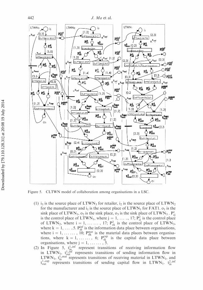
To illustrate the proposed approach in this article, we consider an example ofcollaboration among organisations in a manufacturing supply chain as shown inFigure 4.
In this example, a retailer submits an order to a manufacturer; the manufacturernegotiates with its upstream plants as Plant 1, Plant 2 and Plant 3 negotiate withtheirs upstream plants, respectively, which is a process of sending retailer’srequirement information. From the most upstream plants to the manufacturer,they send acceptance/refusal information to downstream plants according to thechoices of theirs upstream plants as well as theirs production capacity, i.e.,information flows are transmitted two-way in the LSC. If an upstream plant acceptsits downstream plant’s order, then it begins to produce the materials, and mustdeliver materials to downstream plants on time, i.e., material flows are deliveredfrom upstream plants to downstream plants. When the retailer receives products, itpays the manufacturer for products. In turn, the manufacturer pays its upstream
440 J. Ma et al.
Dow
nloa
ded
by [
79.1
10.1
28.3
1] a
t 20:
08 1
9 Ju
ly 2
014
partners that pays theirs upstream partners, i.e., capital flow are moved from themost downstream customers to the upstream supplier step by step.
In Figure 4, if each member in the supply chain can accomplish its own businessprocess at the minimum cost, then this supply chain is a LSC. In this article, werepresent CLTWN model as shown in Figure 5. For simplicity purpose and theassumption on LSC, refusal situation in supply chain has not been considered in thisexample.
Figure 5 shows the segment of CLTWN model that is comprised of three localLTWN: retailer’s LTWN, manufacturer’s LTWN and FAT1’s LTWN. If there is anadequate space, we may draw whole CLTWN and each LTWN is numbered fromenterprise situated in the upstream supply chain to enterprise situated in thedownstream supply chain. In this article, in order to facilitate description, letLTWN3 represent retailer’s LTWN and that is the most downstream in supply chain;Let LTWN2 represent manufacturer’s LTWN and that is in the middle in supplychain; Let LTWN1 represent FAT1’s LTWN. LTWN2 is upstream of LTWN3 and isdownstream of LTWN1. Three extra transitions, t#1 ; t
#2 ; t
#3 , are added in LTWN1,
LTWN2, LTWN3, respectively. Each local workflow is modelled by an LTWN.Notations of Figure 5 are interpreted as follows.
Figure 4. Sequence diagram for cross-organisational collaborative process in a LSC.
Enterprise Information Systems 441
Dow
nloa
ded
by [
79.1
10.1
28.3
1] a
t 20:
08 1
9 Ju
ly 2
014
(1) i3 is the source place of LTWN3 for retailer, i2 is the source place of LTWN2
for the manufacturer and i1 is the source place of LTWN1 for FAT1. o1 is thesink place of LTWN1, o2 is the sink place, o3 is the sink place of LTWN3 . P
1cj
is the control place of LTWN1, where j ¼ 1, . . . .., 17; P2ci is the control place
of LTWN2, where i ¼ 1, . . . . . . , 17; P3ck is the control place of LTWN3,
where k ¼ 1, . . . ..5. Pinfdi is the information data place between organisations,
where i ¼ 1, . . . . . . , 10; Pmatdk is the material data places between organisa-
tions, where k ¼ 1, . . . . . . , 6; Pcapdj is the capital data place between
organisations, where j ¼ 1, . . . . . . , 5.(2) In Figure 5, t1 inf
in represent transitions of receiving information flowin LTWN1, t1 inf
out represents transitions of sending information flow inLTWN1, t
1 matin represents transitions of receiving material in LTWN1, and
t1 capout represents transitions of sending capital flow in LTWN1. t2 inf
in
Figure 5. CLTWN model of collaboration among organisations in a LSC.
442 J. Ma et al.
Dow
nloa
ded
by [
79.1
10.1
28.3
1] a
t 20:
08 1
9 Ju
ly 2
014
represents transitions of receiving information flow in LTWN2, t2 infout
represents transitions of sending information flow in LTWN2,t2 matout represents transitions of delivering materials in LTWN2, t2 mat
in
represents transitions of receiving materials in LTWN2, and t2 capout represents
transitions of paying for suppliers, and t2 capin represents transitions of
receiving capital in LTWN2. t3 infin represents transitions of receiving
information flow in LTWN3, t3 infout represents transitions of sending
information flow in LTWN3, t3 matout represents transitions of delivering
materials in LTWN3 and t3 capin represents transitions of receiving capital in
LTWN3.(3) Pro1 & 2 in labelled function represents first production and second
production, pro1 represents first production, and pro2 represents secondproduction. Com 1 & 2 in labelled function represents first component andsecond component, Com1 represents first component, and Com2 representssecond component.
Obviously, LTWN1, LTWN2 and LTWN3 are sound. According to Definition4.6 and Definition 4.7, we can easily verify that LTWN1, LTWN2 and LTWN3 inFigure 5 are well structured and OR-silent.
In the following, we apply theorem 2 and Corollary 1 to analyse soundness ofCLTWN.
In LTWN1, there are two elementary paths leading from i1 to o1:
d11 is compared with d12, and d31 is compared with d22, and d51 is compared with d32,and d71 is compared with d42, there does not exist pair of data place p and q, andk 2 {1,2} such that:
(1) rinf1 ðpÞ �ck1sinf1 ðqÞ and rinf2 ðqÞ �c1
2sinf2 ðpÞ are simultaneously satisfied;
(2) rinf2 ðpÞ �c12sinf2 ðqÞ and rinf1 ðqÞ �ck
1sinf1 ðpÞ are simultaneously satisfied;
(3) rcap1 ðpÞ �ck1sinf1 ðqÞ and rinf2 ðqÞ �c1
2scap2 ðpÞ are simultaneously satisfied;
444 J. Ma et al.
Dow
nloa
ded
by [
79.1
10.1
28.3
1] a
t 20:
08 1
9 Ju
ly 2
014
(4) rinf1 ðpÞ �ck1smat1 ðqÞ and rmat
2 ðqÞ �c12sinf2 ðpÞ are simultaneously satisfied;
(5) rcap1 ðpÞ �ck1smat1 ðqÞ and rmat
2 ðqÞ �c12scap2 ðpÞ are simultaneously satisfied;
According to Theorem 2, CLTWN12 is 1-soundness. Similarly, Corollary 1 canalso be used to verify the 1-soundness of LTWN3 and CLTWN12.
In Figure 5, there are many paths leading from i2 to o2.The same holds for i1 to o1.For instance, apart from C1
2 and C22 there are other paths combining partial path of C1
2
with partial path of C22 in LTWN2. Similarly, apart from C1
1 and C21 there are other
paths combining partial path of C11 with partial path of C2
1 in LTWN1. While soundnessof CLTWN12 is verified, C1
2 and C22 are examined in LTWN2 and C1
1 and C21 are
examined in LTWN1, then all data places between LTWN1 and LTWN2 are covered,i.e., transitions of receiving and sending message data are localised in C1
2 and C22 of
LTWN2, and transitions of receiving and sending message data are localised inC1
1 and C21 of LTWN1. Therefore, according to above proving procedure of Theorem 2,
it is not necessary to examine other paths in LTWN2 and in LTWN1.CLTWN model shown in Figure 5 has been established in the light of
assumptions and standardisation of collaborating business process betweenorganisations in Section 3 and Definition 4.7. Soundness of this CLTWN modelhas been verified by the method in Section 4. In the actual application, it is possiblethat the example does not satisfy assumptions and standardisation of collaboratingbusiness process between organisations in Section 3 and Definition 4.7. If we addnon OR-silent or loop structure in the example, then make it more realistic. But it isvery difficult to verify soundness of CLTWN model with added non OR-silent orloop structure. This is a topic for future research.
6. Conclusions and future research
This article addresses the issue of business process collaboration betweenorganisations in context of LSC. We presented a formal approach to the modellingand analysis for cross-organisation workflows by Petri nets. First, this article hasproposed the steps of normalisation for collaborating business process betweenorganisations based on characteristics of LSC. Second, we proposed a formal modelof LTPNs by combining labelled Petri nets with TPNs. Third, this article proposedthe LTWNs based on LTPNs and analysis technology for soundness of LTWNs andCLTWNs. Finally, a case study is provided to illustrate how modelling and analysistechnology presented in this article has been used to build cross-organisationworkflow model and analyse its soundness.
The future work should deal with the issue of schedulability analysis and leadtime analysis for LSC from time perspective using reduced CLTWNs. Anotherchallenge task would be studying the method of dynamic collaborating businessprocess between organisations in context of leagile supply chain. It is also valuable toinvestigate the method for verifying the soundness of CLTWN model with addednon OR-silent or loop structures.
Acknowledgements
This research was partially supported by the National Natural Foundation of China withGrant No. 70971107. The authors also would like to thank the anonymous referees for theirinsightful and constructive comments and suggestions.
Enterprise Information Systems 445
Dow
nloa
ded
by [
79.1
10.1
28.3
1] a
t 20:
08 1
9 Ju
ly 2
014
References
Bala, H. and Venkatesh, V., 2007. Assimilation of interorganizational business processstandards. Information Systems Research, 18 (3), 340–362.
Basu, A. and Kumar, A., 2002. Research commentary: workflow management issues ine-business. Information Systems Research, 13 (1), 1–14.
Chebbi, I. and Tata, S., 2005. CoopFlow: a framework for inter-organizational workflowcooperation. In: R. Meersman and Z. Tari, eds. CoopIs/DOA/ODBASE 2005, LNCS,3760, 112–129.
Chebbi, I., Dustdar, S., and Tata, S., 2006. The view-based approach todynamic inter-organizational workflow cooperation. Data & Knowledge Engineering, 56,139–173.
Cheng, A., Esparza, J., and Palsberg, J., 1995. Complexity results for 1-safe nets. TheoreticalComputer Science, 147 (1–2), 117–136.
Du, Y.Y., Jiang, C.J., and Zhou, M.C., 2007. Modeling and analysis of real-time cooperativesystems using Petri nets. IEEE Transactions on Systems, Man, and Cybernetics – Part A:Systems and Humans, 37 (5), 643–654.
Du, Y.Y., Jiang, C.J., and Zhou, M.C., 2009a. A Petri net-based model for verification ofobligations and accountability in cooperative systems. IEEE Transactions on Systems,Man, and Cybernetics-Part A: Systems and Humans, 39 (2), 299–308.
Du, Y., et al., 2009b. Modeling and monitoring of E-commerce workflows. InformationSciences, 179, 995–1006.
Du, Y., Qi, L., and Zhou, M., 2011. A vector matching method for analyzing logic Petri nets.Enterprise Information Systems, 5 (4), 449–468.
Fung, R.Y., Au, Y.M., and Jiang, Z.B., 2003. Supply chain workflow modelling using XML-formatted modular Petri nets. International Journal of Advanced ManufacturingTechnology, 22, 587–601.
Hruz, B. and Zhou, M.C., 2007.Modeling and control of discrete-event dynamical systems: withPetri nets and other tools. London: Springer-Verlag, 5–18.
Li, L., 2007. Supply chain management: concepts, techniques and practices-enhancing valuethrough collaboration. New York: World Scientific Publishing.
Li, L. and Warfield, J., 2011. Perspectives on quality coordination and assurance in globalsupply chains. International Journal of Production Research, 49 (1), 1–4.
Lindert, F. and Deiters, W., 1999. Modeling inter-organizational processes with process modelfragments. In: Proceedings of the workshop on enterprise-wide and cross-enterprise workflowmanagement, 6 October 1999, Paderborn, Germany.
Liu, D.R. and Shen, M., 2003. Workflow modeling for virtual processes: an order-preservingprocess-view approach. Information System, 28, 505–532.
Liu, D.R. and Shen, M., 2004. Business-to-business workflow interoperation based onprocess-views. Decision Support System, 38, 399–419.
Liu, J., Zhang, S., and Hu, J., 2005. A case study of an inter-enterprise workflow-supportedsupply chain management system. Information & Management, 42, 441–454.
Mason-jones, R., Naylor, B., and Towill, D.R., 2000. Lean, agile or leagile? Matching yoursupply chain to the marketplace. International Journal of Production Research, 38, 4061–4070.
Murata, T., 1989. Petri nets: properties, analysis and applications. In: Proceedings of the IEEE.Vol. 77. USA: IEEE, 541–580.
Naylor, J.B., Naim, M.M., and Berry, D., 1999. Leagility: integrating the lean and agilemanufacturing paradigms in the total supply chain. International Journal of ProductionEconomics, 62, 107–118.
Penczek, W., 2006. Petri nets with time. Studies in Computational Intelligence, 20, 3–27.Quartel, D., et al., 2009. Model-driven development of mediation for business services using
COSMO. Enterprise Information Systems, 3 (3), 319–345.Reeve, J., 2002. The financial advantages of the lean supply chain. Supply Chain Management
Review, March/April, 42–49.Rivera, L., et al., 2007. Beyond partnerships: the power of lean supply chains. In: J. Hosang,
F.C. Fengshan, and J. Bongju, eds. Trends in supply chain design and management.London: Springer, 241–267.
446 J. Ma et al.
Dow
nloa
ded
by [
79.1
10.1
28.3
1] a
t 20:
08 1
9 Ju
ly 2
014
Salimifard, K. and Wright, M., 2001. Petri net-based modelling of workflow systems: anoverview. European Journal of Operational Research, 134, 664–676.
Schulz, K.A. and Orlowska, M.E., 2004. Facilitating cross-organizational workflows with aworkflow view approach. Data & Knowledge Engineering, 51, 109–147.
Stratton, R. and Warburton, R.D., 2003. The strategic integration of agile and lean supply.International Journal of Production Economics, 85, 183–198.
Tan, W., et al., 2008. A business process intelligence system for enterprise process performancemanagement. IEEE Transactions on SMC: Part C, 38 (6), 745–756.
Tan, W., et al., 2010. A methodology toward manufacturing grid-based virtual enterpriseoperation platform. Enterprise Information Systems, 4 (3), 283–309.
Tata, S., Klai, K., and M’bareck, N., 2008. CoopFlow: a bottom-up approach to workflowcooperation for short-term virtual enterprises. IEEE Transactions on Services Computing,1 (4), 214–228.
van der Aalst, W., 1998a. The application of Petri nets to workflow management. The Journalof Circuits, Systems and Computers, 8 (1), 21–26.
van der Aalst, W., 1998b. Modeling and analysis interorganizational workflows. In: Firstinternational conference on application of concurrency to system design. (ACSD’98), 23–26March 1998, Fukushima, Japan. USA: IEEE Computer Society, 262–273.
van der Aalst, W., 1999a. Interorganizational workflows: an approach based onmessage sequence charts and Petri nets. Systems Analysis, Modelling. Simulation, 34 (3),335–367.
van der Aalst, W., 1999b. Process-oriented architectures for electronic commerce andinterorganizational workflow. Information Systems, 24 (8), 639–671.
van der Aalst, W., 2000a. Workflow verification: finding control-flow errors using Petri-net-based techniques. In: W. van der Aalst, et al., eds. Business process management LNCS,1806, 161–183.
van der Aalst, W., 2000b. Loosely couple interorganizational workflows: modelling andanalyzing workflows crossing organizational boundaries. Information & Management, 37,67–75.
van der Aalst, W. and Kumar, A., 2003. XML-based schema definition for support ofinterorganizational workflow. Information System Research, 14 (1), 23–46.
van der Aalst, W., 2004. Business process management demystified: a tutorial on modelssystems and standards for workflow management. In: J. Desel, W. Reisig, and G.Rozenberg, eds. ACPN 2003, LNCS, 3098, 1–65.
Verbeek, H. and Van der Aalst, W., 2004. XRL/Woflan: verification and extensibility of anXML/Petri-net-based language for inter-organizational workflows. Information Technol-ogy and Management, 5, 65–110.
Vitasek, K., Manrodt, K.B., and Abbott, J., 2005. What makes a lean supply chain. SupplyChain Management Review, 39–45.
Wu, S., Xu, L., and He, W., 2009. Industry-oriented enterprise resource planning. EnterpriseInformation Systems, 3 (4), 409–424.
Xu, L., 2011. Information architecture for supply chain quality management. InternationalJournal of Production Research, 49 (1), 183–198.
Xu, L., Liang, N., and Gao, Q., 2008a. An integrated approach for agricultural ecosystemmanagement. IEEE Transactions on SMC: Part C, 38 (4), 590–599.
Xu, L., et al., 2008b. An approach to enterprise process dynamic modeling supportingenterprise process evolution. Information Systems Frontiers, 10 (5), 611–624.
Xu, L., et al., 2009. Modelling and analysis techniques for cross-organizational workflowsystems. Systems Research and Behavioral Science, 26, 367–389.
Xu, S., 2008. The concept and theory of material flow. Information Systems Frontiers, 10 (5),601–609.
Xu, S., 2009. Theory of six forces of essential factors of production. Systems Research andBehavioral Science, 26 (2), 211–218.
Zisman, M.D., 1977. Representation, specification and automation of office procedures. Thesis(PhD). The Wharton School, University of Pennsylvania, Philadelphia, PA.