1 MODELLING AND SIMULATION OF DOUBLY-FED INDUCTION GENERATOR CONNECTED WITH WIND TURBINE By NITEESH SONKER (111EE0054) SOUMYA RANJAN DAS (111EE0207) LAXMAN MOHAPATRO (111EE0220) DEPARTMENT OF ELECTRICAL ENGINEERING NATIONAL INSTITUTE OF TECHNOLOGY ROURKELA, ODISHA
Transcript
1
MODELLING AND SIMULATION OF DOUBLY-FED
INDUCTION GENERATOR CONNECTED WITH WIND
TURBINE
By
NITEESH SONKER (111EE0054)
SOUMYA RANJAN DAS (111EE0207)
LAXMAN MOHAPATRO (111EE0220)
DEPARTMENT OF ELECTRICAL ENGINEERING
NATIONAL INSTITUTE OF TECHNOLOGY
ROURKELA, ODISHA
2
MODELLING AND SIMULATION OF DOUBLY-FED
INDUCTION GENERATOR CONNECTED WITH WIND
TURBINE
A Thesis submitted in partial fulfilment of the requirements for the degree of
Bachelor of Technology in “Electrical Engineering”
By
NITEESH SONKER (111EE0054)
SOUMYA RANAJN DAS (111EE0207)
LAXMAN MOHAPATRO (111EE0220)
Under guidance of Dr. Sanjib Ganguly
DEPARTMENT OF ELECTRICAL ENGINEERING
NATIONAL INSTITUTE OF TECHNOLOGY
ROURKELA, ODISHA
3
ACKNOWLEDGEMENT
We have been extremely lucky to have Dr. Sanjib Ganguly, Department of Electrical
Engineering, NIT, Rourkela as our Project Guide. He enlivened us to make enthusiasm for
Wind Energy Systems, taught us nature and standard of exploration and guided us through
the culmination of this postulation work. Working with Dr. Sanjib Ganguly was very
delightful, rousing and learning background. We are obliged to him and express our profound
feeling of appreciation for his direction and backing. We are exceedingly obliged for the
support of Department of Electrical Engineering, NIT, Rourkela for giving us different
offices which have been exceptionally valuable.
We express uncommon because of every one of our companions, for being there, at whatever
point we required them. We devote this Thesis to my family and companions.
NITEESH SONKER (111EE0054)
SOUMYA RANJAN DAS (111EE0207)
LAXMAN MOHAPATRO (111EE0220)
B.TECH, ELECTRICAL ENGINEERING
NIT, Rourkela
4
CERTIFICATE
This is to confirm that the thesis entitled "Modelling and Simulation of Doubly Fed Induction
Generator Based Wind Turbine", submitted by Niteesh Sonker (111EE0054), Soumya Ranjan
Das(111EE0207) and Laxman Mohapatro (110EE0220) in partial satisfaction of the
necessities for the grant of Bachelor of Technology in Electrical Engineering amid session
2014-2015 at National Institute of Technology, Rourkela. A bonafide record of project work
has been done by them under my guidance and supervision.
The students have satisfied all the recommended prerequisites. The Thesis which is in view
of students own work, have not submitted somewhere else for a Degree/ Diploma. In my
view, the thesis is of standard needed for the recompense of a Bachelor of Technology degree
in Electrical Engineering.
Place: Rourkela
Dept. of Electrical Engineering Dr. Sanjib Ganguly
National institute of Technology Assistant Professor
Rourkela-769008
DEPARTMENT OF ELECTRICAL ENGINEERING
NATIONAL INSTITUTE OF TECHNOLOGY
ROURKELA, ODISHA
5
ABSTRACT
This work presents the modelling of DFIG (Doubly-Fed Induction Machine) using active
and reactive power transfer model and the controlling strategy of DFIG using multivariable
control method. This paper also represents the free acceleration characteristics of the
machine. Real/Reactive powers are used in the matrix as state variables. Multi-loop control
scheme is used for the control. The controller part uses six compensators. The matrix method
used this paper increased the robustness of the machine as power waveforms are independent
of d-q reference variable. The simulation of modelling and controlling is done using
MATLAB/SIMULINK and the waveforms are plotted.
6
CONTENTS
Acknowledgement 3
Certificate 4
Abstract 5
Symbols Used 8
Figures List 9-10
Chapter-1 : Introduction
1.1 Wind Energy 11
1.2 Terms And Definitions 11
1.2.1 Power Contained in the Wind 11
1.2.2 Tip speed Ratio 11
1.2.3 Power coefficient 12
1.2.4 Pitch Angle 12
1.3 Types of Wind Turbine 12
1.3.1 Constant-Speed Wind Turbine 12
` 1.3.2 Variable Speed Wind Turbine 13
1.3.3 Variable Speed Wind Turbine with DFIG 13
1.3.4 DFIG Systems for Wind Turbines 14
1.4 Power Flow in DFIG 14-15
Chapter-2: Modelling of Doubly-Fed Induction Generator
2.1 Transformation of abc to dq0 reference 16-18
2.2 Modelling of DFIG Wind Energy Systems 18-20
2.3 Modelling of DFIG Using Instantaneous Power Components 20-23
2.4 Grid-Side Converter and Filter Model 23-25
2.5 Model OF Wind Turbine 25
2.6 Linearization of model of a DFIG machine 26-28
7
2.7 Free acceleration characteristics of induction machine 28
Chapter-3: Control Strategy of DFIG
3.1 Sequential loop closing 29
3.2 Design of control system for a DFIG wind turbine system
3.2.1 Controller Design Method 29
3.2.2 Design of the Rotor-Side Controllers 30-31
3.2.3 Rotor Speed Controller Design 31
3.2.4 Grid-Side Controller Design 31-32
3.2.5 DC-Link Voltage Controller Design 32-33
3.3 Parameters calculation for controllers 33-34
Chapter-4: Simulation and Results
4.1 Design of Wind Turbine 35-36
4.2 Torque-Slip characteristics of Induction machine 36
4.3 Simulink for controlling of DFIG 37-40
4.4 Free acceleration characteristics of Induction Machine 41-45
Conclusion 46
References 47-48
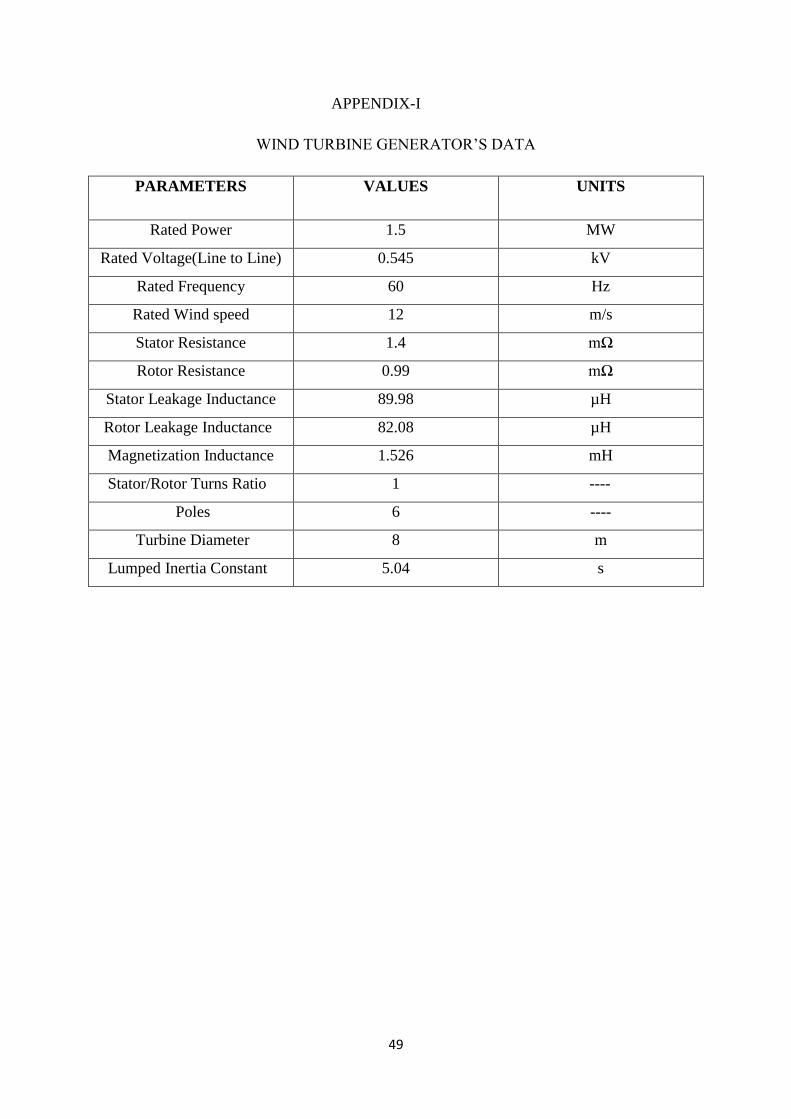
Appendix 49
8
NOTATION AND SYMBOL USED
= stator inductance
= magnetizing inductance
= rotor inductances
= rotor speed of the induction machine
=slip frequency
( )= instantaneous grid side active power
( )= instantaneous grid side reactive power
( )= instantaneous rotor side active power
( )= instantaneous rotor side reactive power
= DC link voltage
=stator dq reference voltage
=rotor dq reference voltage
=stator dq reference current
=rotor dq reference current
= stator flux in dq frame
= rotor flux in dq frame
= variables containing rotor side dq voltage
= variables containing grid side dq voltage
= mechanical input power
= mechanical torque
= electromagnetic torque
= number of poles
J = moment of inertia of wind turbine (Kg –m2 )
9
LIST OF FIGURES
Fig 1.1 - Schematic Diagram for Fixed speed Wind Turbine
Fig 1.2 - Schematic Diagram for Variable speed Wind Turbine
Fig 1.3- Schematic diagram for Doubly-fed Wind Turbine
Fig 1.4 Doubly-Fed Induction Generator Principle
Fig 1.5- Flow of power in DFIG during Super-synchronous speed
Fig 1.6- Flow of power in DFIG during Sub-Synchronous mode
Fig 2.1 abc to dq0 reference axis
Fig.2.2 Schematic diagram of the DFIG based wind turbine system
Fig 2.3 Equivalent circuit of grid side filter
Fig.3.1 schematic diagram for the control of grid side and rotor side converters.
Fig.4.1(a) Power coefficient Vs Tip speed ratio characteristics
Fig 4.1(b)- Power output of turbine Vs Wind speed characteristics
Fig 4.2- Torque vs speed characteristics
Fig.4.3 Simulink Block Diagram for controlling of DFIG
Fig.4.3.1 wind speed variation with time
Fig 4.3.2 Three phase supply to stator
Fig 4.3.3 Stator voltage along d-axis
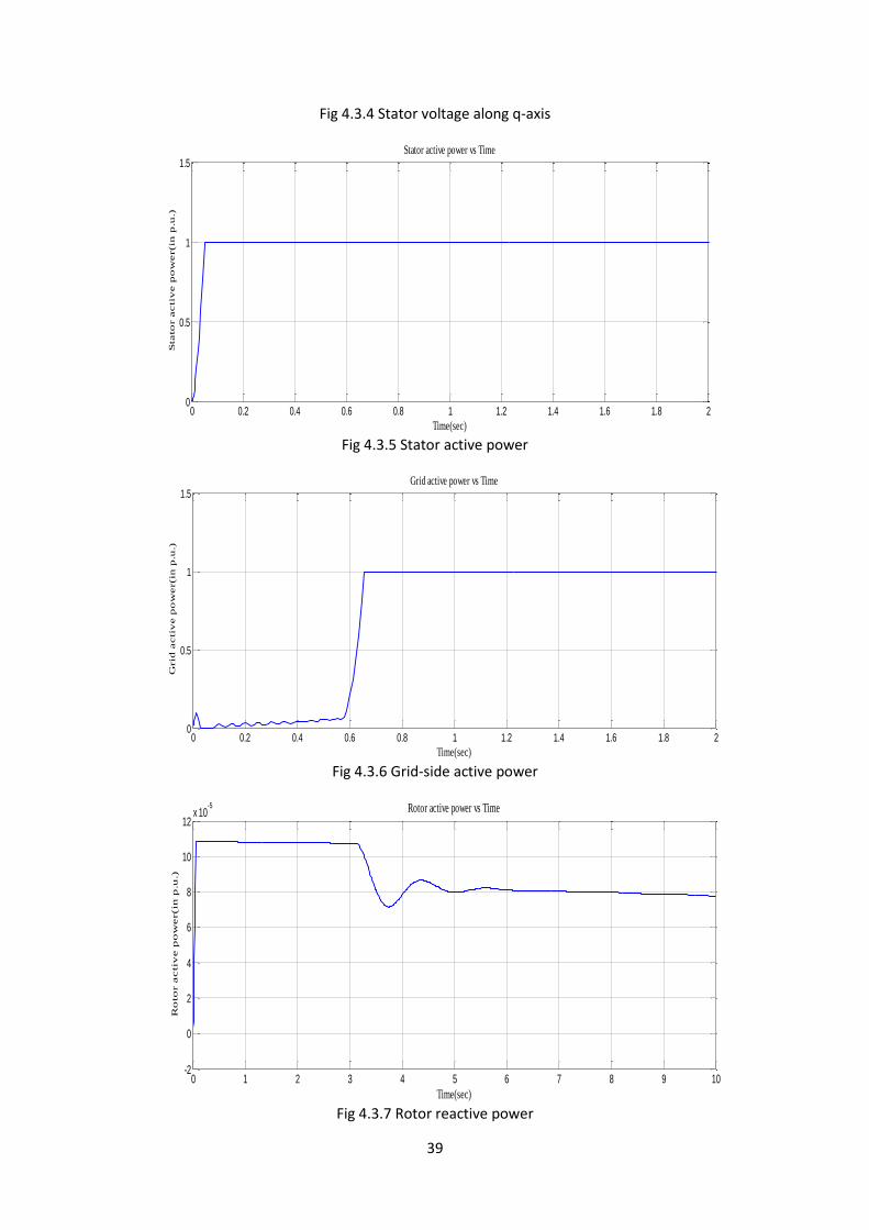
Fig 4.3.4 Stator voltage along q-axis
Fig 4.3.5 Stator active power
Fig 4.3.6 Grid-side active power
Fig 4.3.7 Rotor reactive power
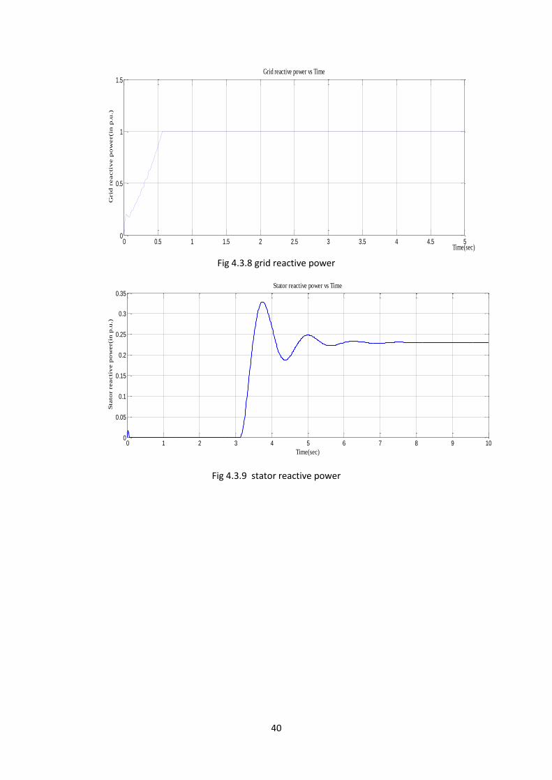
Fig 4.3.8 grid reactive power
Fig 4.3.9 stator reactive power
10
Fig 4.4.1- Simulink Block Diagram for Free acceleration characteristics of Induction machine
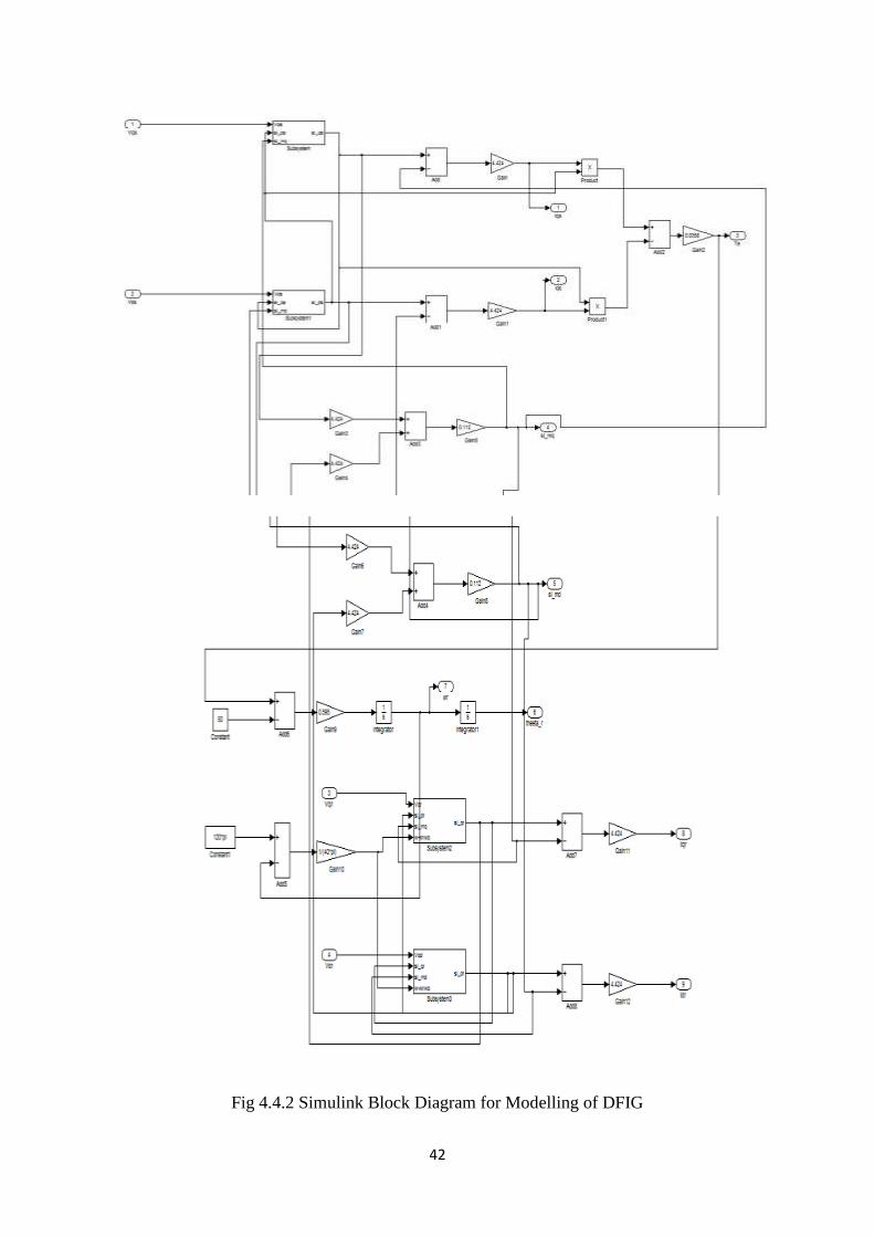
Fig 4.4.2 Simulink Block Diagram for Modelling of DFIG
Fig 4.4.3 Torque-speed characteristics
Fig 4.4.4 Stator a-phase current
Fig 4.4.5 Stator b-phase current
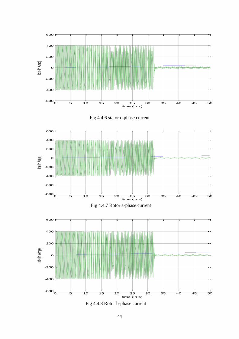
Fig 4.4.6 stator c-phase current
Fig 4.4.7 Rotor a-phase current
Fig 4.4.8 Rotor b-phase current
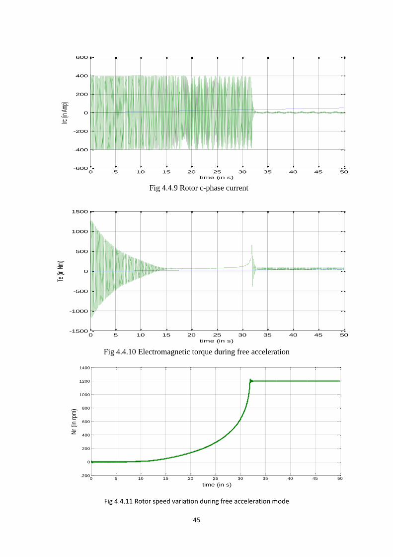
Fig 4.4.9 Rotor c-phase current
Fig 4.4.10 Electromagnetic torque during free acceleration
Fig 4.4.11 Rotor speed variation during free acceleration mode
11
CHAPTER-1
INTRODUCTION
1.1 Motivation
Energy of wind is the most accessible and exploitable types of renewable vitality. Because of
rapidly need for electrical energy and exhaustion of fossil fuels, for example, coal and oil,
whose stores are restricted, this issues drove researchers to create another source of energy
for era of power. The most reluctant source which fulfills non-contamination, accessible in
wealth, less costlier to tackle both in low-scale and high-scale frameworks is wind.
For variable speed range, power can be supplied to grid by controlling rotor power from a
variable frequency source for slip-ring induction machine. The bidirectional flow of power
from rotor of the induction machine can be done by connecting ac/dc/ac converters across the
rotor. This type of system is called Doubly-Fed Induction Generator (DFIG) where power
flows bi-directionally.
1.2 Terms and Definitions -
1.2.1 Power contained in the wind-
The kinetic energy of the air masses per unit time.[1]
( ) ( )
(1.1)
1.2.2 Tip speed Ratio (TSR)-
The ratio of the wind flowing from the tip of the blade to the wind velocity. It is denoted by
. [1]
(1.1)
12
1.2.3 Power coefficient-
The ratio of power output of the machine to the power contained in the wind. It is denoted by
Cp. [1]
1.2.4 Pitch Angle-
It is angle between the chord of aerofoil section and the plane of revolution..
1.3 Types of Wind Turbine System -
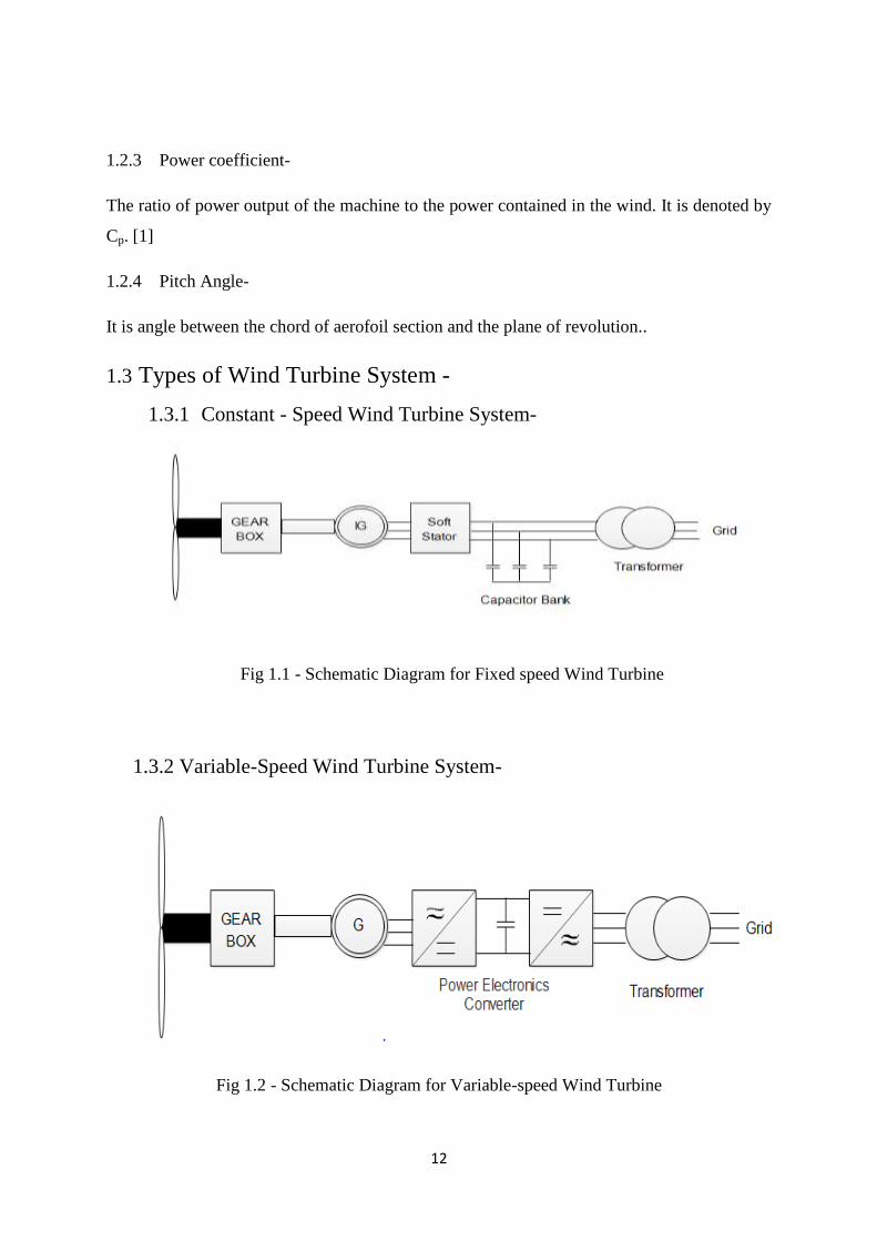
1.3.1 Constant - Speed Wind Turbine System-
Fig 1.1 - Schematic Diagram for Fixed speed Wind Turbine
1.3.2 Variable-Speed Wind Turbine System-
Fig 1.2 - Schematic Diagram for Variable-speed Wind Turbine
13
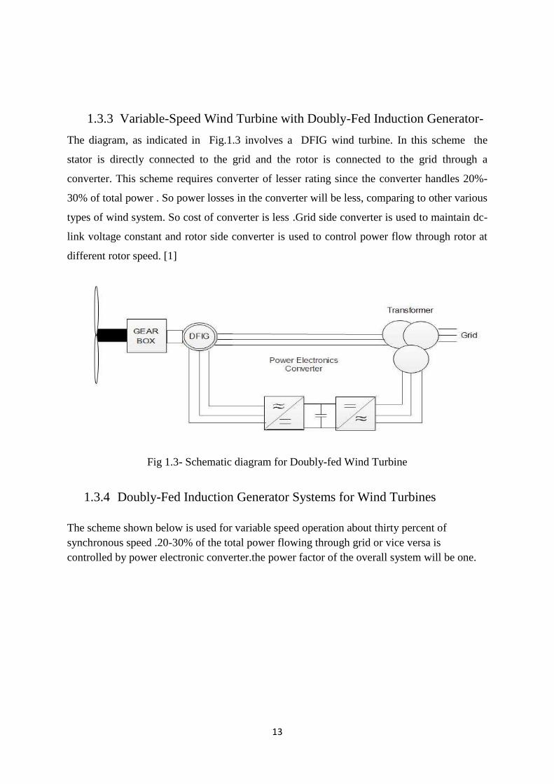
1.3.3 Variable-Speed Wind Turbine with Doubly-Fed Induction Generator-
The diagram, as indicated in Fig.1.3 involves a DFIG wind turbine. In this scheme the
stator is directly connected to the grid and the rotor is connected to the grid through a
converter. This scheme requires converter of lesser rating since the converter handles 20%-
30% of total power . So power losses in the converter will be less, comparing to other various
types of wind system. So cost of converter is less .Grid side converter is used to maintain dc-
link voltage constant and rotor side converter is used to control power flow through rotor at
different rotor speed. [1]
Fig 1.3- Schematic diagram for Doubly-fed Wind Turbine
1.3.4 Doubly-Fed Induction Generator Systems for Wind Turbines
The scheme shown below is used for variable speed operation about thirty percent of
synchronous speed .20-30% of the total power flowing through grid or vice versa is
controlled by power electronic converter.the power factor of the overall system will be one.
14
The converter are controlled by PWM Pulse generators.
Fig 1.4 Doubly-Fed Induction Generator Principle
The converters are connected in back to back fashion with a transformer to the grid that
includes two converters.In between the two converters a dc capacitor is connected, to keep
the voltage variances (or swell) in the link voltage to a minimum quantity.
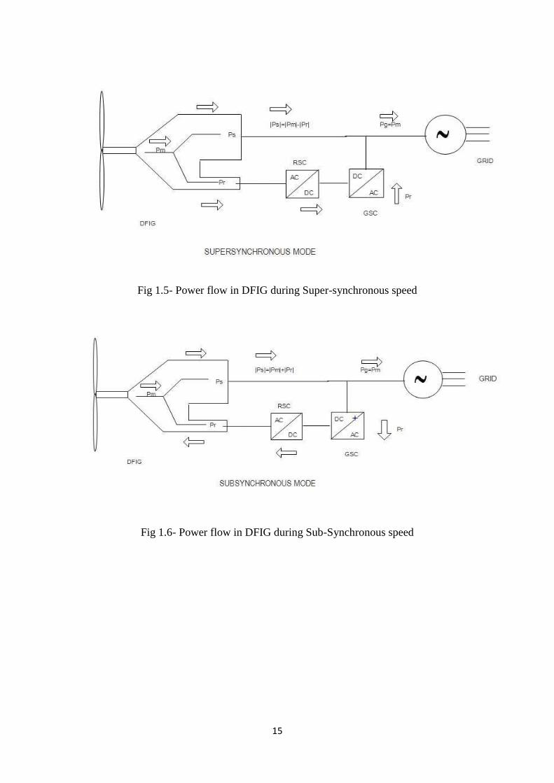
1.4 Power flow in DFIG
To compute the power flow of the DFIG scheme, the apparent power is fed to the DFIG
through the stator and rotor circuit must be resolved. DFIG can run in two method for
operation, for example, sub-synchronous and super-synchronous mode in view of the rotor
speed beneath or more the synchronous speed. The flow of powerin the rotor of a doubly fed
induction machine has three parts.[1,2]
These are
1) The electromagnetic power traded between the stator and the rotor through the air gap
which can be characterized as the air gap power Ps.
2) The mechanical force Pm traded between the rotor and shaft.
3) Pr (slip power) which is exchanged between the rotor and load through the rotor slip-
rings. These three segments of rotor force are subordinate, in sub- and super-synchronous
methods of operation, as indicated in figure 1.5
15
Fig 1.5- Power flow in DFIG during Super-synchronous speed
Fig 1.6- Power flow in DFIG during Sub-Synchronous speed
16
CHAPTER-2
MODELLING OF DOUBLY-FED INDUCTION
GENERATOR (DFIG)
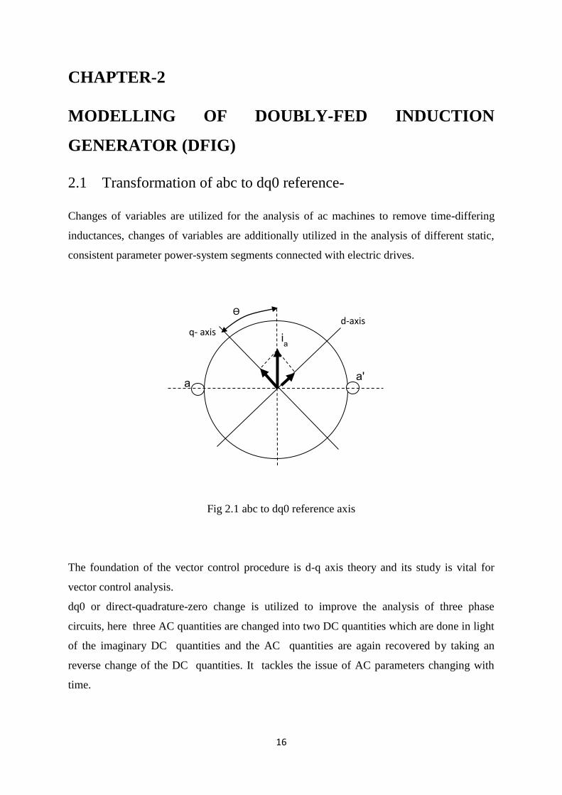
2.1 Transformation of abc to dq0 reference-
Changes of variables are utilized for the analysis of ac machines to remove time-differing
inductances, changes of variables are additionally utilized in the analysis of different static,
consistent parameter power-system segments connected with electric drives.
Fig 2.1 abc to dq0 reference axis
The foundation of the vector control procedure is d-q axis theory and its study is vital for
vector control analysis.
dq0 or direct-quadrature-zero change is utilized to improve the analysis of three phase
circuits, here three AC quantities are changed into two DC quantities which are done in light
of the imaginary DC quantities and the AC quantities are again recovered by taking an
reverse change of the DC quantities. It tackles the issue of AC parameters changing with
time.
ia
a a'
d-axis q- axis
Ѳ
17
.The orthogonally placed balanced windings, are known as d- and q- windings which are
dealt with as stationary or moving in respect to the stator.
In the stationary edge of reference, the d-q axis are viewed as fixed on the stator, with either d
or q axis corresponding with the a-phases axis of the stator. In the rotating frame, the rotating
d-q axis are considered either fixed on the rotor or made to move at the synchronous speed.
Park‟s transformation considers a frame of reference on the rotor. The scientist Parks gave
this for a synchronous machine which is the same as a synchronous frame of reference. For
induction motors, it is necessary to distinguish between a synchronous reference frame and a
reference frame on the rotor.
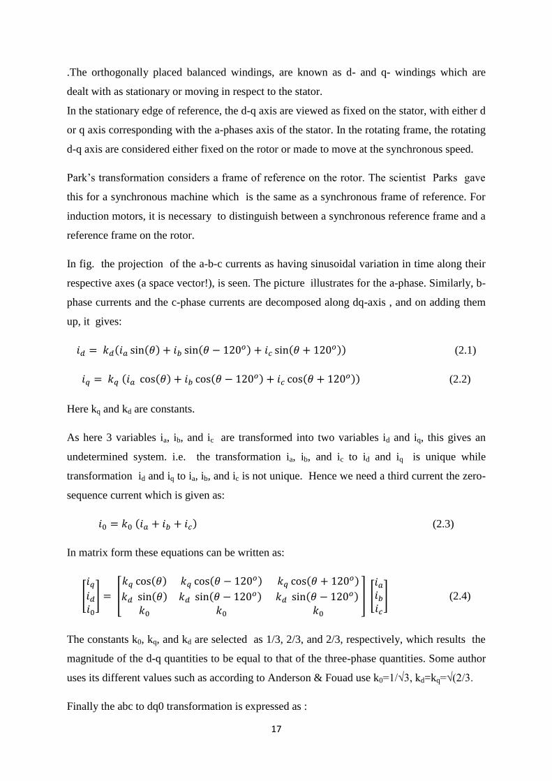
In fig. the projection of the a-b-c currents as having sinusoidal variation in time along their
respective axes (a space vector!), is seen. The picture illustrates for the a-phase. Similarly, b-
phase currents and the c-phase currents are decomposed along dq-axis , and on adding them
up, it gives:
( ( ) ( ) (
)) (2.1)
( ( ) ( ) (
)) (2.2)
Here kq and kd are constants.
As here 3 variables ia, ib, and ic are transformed into two variables id and iq, this gives an
undetermined system. i.e. the transformation ia, ib, and ic to id and iq is unique while
transformation id and iq to ia, ib, and ic is not unique. Hence we need a third current the zero-
sequence current which is given as:
( ) (2.3)
In matrix form these equations can be written as:
[
] [
( ) ( ) (
)
( ) ( ) (
)
] [
] (2.4)
The constants k0, kq, and kd are selected as 1/3, 2/3, and 2/3, respectively, which results the
magnitude of the d-q quantities to be equal to that of the three-phase quantities. Some author
uses its different values such as according to Anderson & Fouad use k0=1/√3, kd=kq=√(2/3.
Finally the abc to dq0 transformation is expressed as :
18
[
]
[ ( ) ( ) ( )
( ) ( ) ( )
] [
]
(2.5)
(2.6)
Where
[ ( ) ( ) ( )
( ) ( ) ( )
] (2.7)
Thus the dq0 to abc transformation is expressed as :
(2.8)
Where
[ ( ) ( )
( ) ( ) ( ) ( )
]
2.2 Modelling of DFIG Wind Energy Systems-
Fig.2.2 Schematic diagram of the DFIG-based wind generation system
19
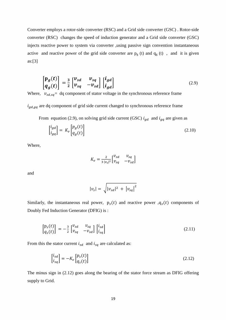
Converter employs a rotor-side converter (RSC) and a Grid side converter (GSC) . Rotor-side
converter (RSC) changes the speed of induction generator and a Grid side converter (GSC)
injects reactive power to system via converter ,using passive sign convention instantaneous
active and reactive power of the grid side converter are pg (t) and qg (t) , and it is given
as:[3]
* ( )
( )+
[
] [ ] (2.9)
Where, = dq component of stator voltage in the synchronous reference frame
are dq component of grid side current changed to synchronous reference frame
From equation (2.9), on solving grid side current (GSC) and are given as
[ ] *
( )
( )+ (2.10)
Where,
| | *
+
and
| | √| | | |
Similarly, the instantaneous real power, ( ) and reactive power , ( ) components of
Doubly Fed Induction Generator (DFIG) is :
[ ( ) ( )
]
*
+ [ ] (2.11)
From this the stator current and are calculated as:
[ ] [
( ) ( )
] (2.12)
The minus sign in (2.12) goes along the bearing of the stator force stream as DFIG offering
supply to Grid.
20
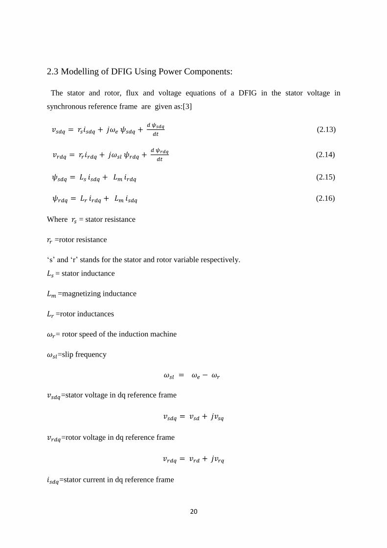
2.3 Modelling of DFIG Using Power Components:
The stator and rotor, flux and voltage equations of a DFIG in the stator voltage in
synchronous reference frame are given as:[3]
(2.13)
(2.14)
(2.15)
(2.16)
Where = stator resistance
=rotor resistance
„s‟ and „r‟ stands for the stator and rotor variable respectively.
= stator inductance
=magnetizing inductance
=rotor inductances
= rotor speed of the induction machine
=slip frequency
=stator voltage in dq reference frame
=rotor voltage in dq reference frame
=stator current in dq reference frame
21
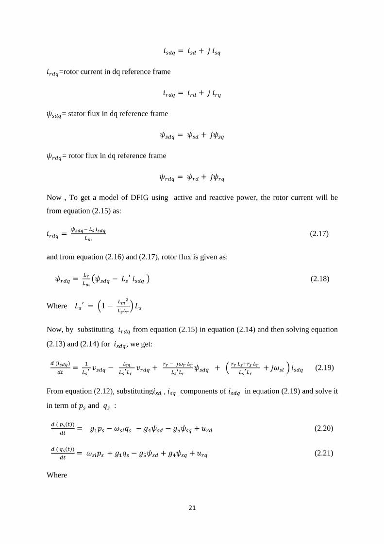
=rotor current in dq reference frame
= stator flux in dq reference frame
= rotor flux in dq reference frame
Now , To get a model of DFIG using active and reactive power, the rotor current will be
from equation (2.15) as:
(2.17)
and from equation (2.16) and (2.17), rotor flux is given as:
(
) (2.18)
Where (
)
Now, by substituting from equation (2.15) in equation (2.14) and then solving equation
(2.13) and (2.14) for , we get:
( )
(
) (2.19)
From equation (2.12), substituting , components of in equation (2.19) and solve it
in term of and :
( ( ))
(2.20)
( ( ))
(2.21)
Where
22
| |
(2.22)
(2.23)
(
)
(
)
Solving the stator voltage equations for
( )
| | ( ) (2.24)
( )
| | ( ) (2.25)
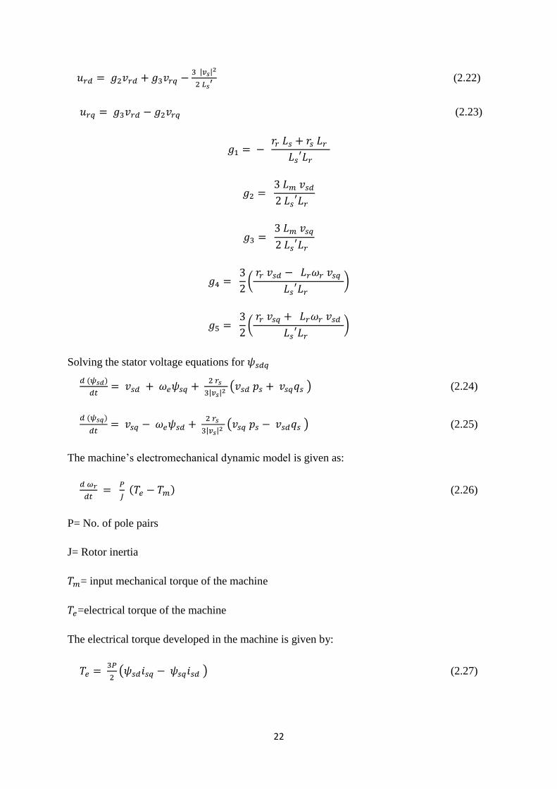
The machine‟s electromechanical dynamic model is given as:
( ) (2.26)
P= No. of pole pairs
J= Rotor inertia
= input mechanical torque of the machine
=electrical torque of the machine
The electrical torque developed in the machine is given by:
( ) (2.27)
23
By substituting for and from equation (2.12) in equation (2.26) and then putting the
value of in equation (2.27),then we get:
(2.28)
Where
(
| | )
(
| | )
The Matrix model of the Doubly-Fed induction machine is shown below in state variable
matrix form is obtained from equation (2.20) to (2.25) and (2.28), is given as:
[ ]
[
| |
| |
| |
| |
]
[ ]
[
]
(2.29)
The above model of DFIG we got, is a nonlinear dynamic model because the coefficients of
the matrix input are functions of the state variables.
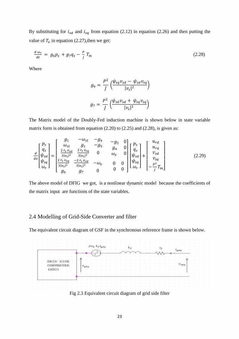
2.4 Modelling of Grid-Side Converter and filter
The equivalent circuit diagram of GSF in the synchronous reference frame is shown below.
Fig 2.3 Equivalent circuit diagram of grid side filter
24
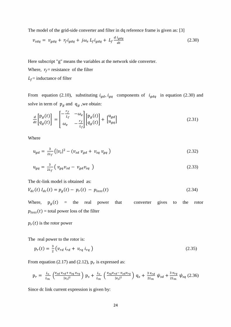
The model of the grid-side converter and filter in dq reference frame is given as: [3]
(2.30)
Here subscript "g" means the variables at the network side converter.
Where, = resistance of the filter
= inductance of filter
From equation (2.10), substituting , components of in equation (2.30) and
solve in term of and ,we obtain:
* ( )
( )+ [
] * ( )
( )+ *
+ (2.31)
Where
(| |
( ) (2.32)
( ) (2.33)
The dc-link model is obtained as:
( ) ( ) ( ) ( ) ( ) (2.34)
Where, ( ) = the real power that converter gives to the rotor
( ) = total power loss of the filter
( ) is the rotor power
The real power to the rotor is:
( )
( ) (2.35)
From equation (2.17) and (2.12), is expressed as:
(
| | )
(
| | )
(2.36)
Since dc link current expression is given by:
25
( ) ( )
In equation (2.34) by substituting the value of dc link model is deduced as : [3]
( )
( )
( ) ( )
(2.37)
2.5 Model OF Wind Turbine
The mechanical power extracted by a wind turbine is expressed as
( )
(2.38)
Where R= Radius of wind turbine
= density of air mass
= wind speed
= wind turbine power coefficient which is a depedent of TSR and pitch angle β of the
turbine
( )
Power output coefficient is related to of tip speed ratio (TSR) and pitch angle β of the
wind turbine blade as the following expression:
( ) (
)
( ) (2.39)
where
( )
( )
From experimentally it is found that
For a high-rating wind turbine, the maximum mechanical power extracted at optimum values
of TSR in range of 5 to 8. It is shown that and the maximum value of is
26
0.5926 which is Betz limit. Practically for an optimum value of TSR, power coefficient is
considered about 0.51 for high-rating wind turbines system.
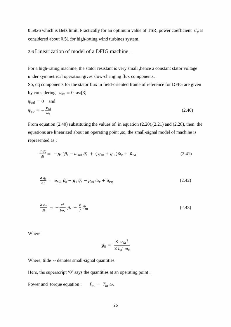
2.6 Linearization of model of a DFIG machine –
For a high-rating machine, the stator resistant is very small ,hence a constant stator voltage
under symmetrical operation gives slow-changing flux components.
So, dq components for the stator flux in field-oriented frame of reference for DFIG are given
by considering as:[3]
and
(2.40)
From equation (2.40) substituting the values of in equation (2.20),(2.21) and (2.28), then the
equations are linearized about an operating point ,so, the small-signal model of machine is
represented as :
( ) (2.41)
(2.42)
(2.43)
Where
Where, tilde ~ denotes small-signal quantities.
Here, the superscript „0‟ says the quantities at an operating point .
Power and torque equation :
27
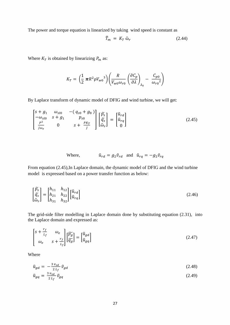
The power and torque equation is linearized by taking wind speed is constant as
(2.44)
Where is obtained by linearizing as:
(
)(
(
)
)
By Laplace transform of dynamic model of DFIG and wind turbine, we will get:
[
( )
] [
] [
] (2.45)
Where, and
From equation (2.45),In Laplace domain, the dynamic model of DFIG and the wind turbine
model is expressed based on a power transfer function as below:
[
] [
] [ ] (2.46)
The grid-side filter modelling in Laplace domain done by substituting equation (2.31), into
the Laplace domain and expressed as:
[
] [ ] [
] (2.47)
Where
(2.48)
(2.49)
28
from equation (2.47),on solving for and the GSF model in the Laplace domain is
given by:
[ ] *
+ [
] (2.50)
Where
from equation (2.27), the linearized model of dc link is given by:
(2.51)
Where
(2.52)
From equation (2.34), dc link model in the Laplace domain is given by:
(2.53)
2.7 Free acceleration characteristics of Induction machine-
For analysis of induction machines during no load condition which is also known as free
Acceleration mode of machine from stall, there is need of study of relationship between
torque and speed. For this purpose free acceleration of the squirrel cage induction machine
are simulated on MATLAB and studies are performed. [6]
29
CHAPTER-3
CONTROL STRATEGY OF DFIG WIND TURBINE
3.1 Sequential loop closing (SLC):
The sequential loop closing (SLC) scheme is also known as multi-loop control method
that is used for multivariable control processes . In this Scheme, each controller is
sequentially designed from the transfer function of every pair of inputs and outputs
considering the former controllers is a part of it and closed. In it , the single-input single-
output (SISO) auto-tuning technique is used . The transfer function of the latter pair of
inputs and outputs is varied considerably as the former loops are closed. [14]
3.2 Design of control system for a DFIG wind turbine system:
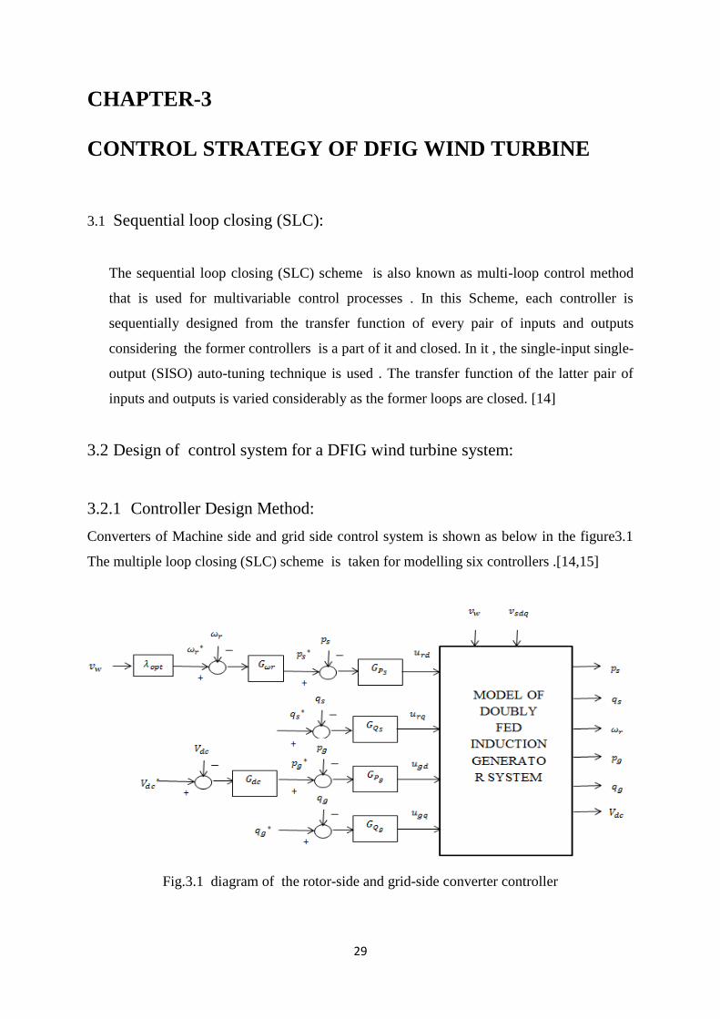
3.2.1 Controller Design Method:
Converters of Machine side and grid side control system is shown as below in the figure3.1
The multiple loop closing (SLC) scheme is taken for modelling six controllers .[14,15]
Fig.3.1 diagram of the rotor-side and grid-side converter controller
30
3.2.2 Rotor-Side Controller design
Stator Reactive and Active Power Controllers Design:
By taking ( ) as the 1st input- output equation (2.47) and
Imposing ,we derived the first SISO subsystem for controller design as:
(3.1)
The first controller is designed as:
( ) (3.2)
From equation (3.1) and (3.2) the closed-loop design of the 1st subsystem in Laplace mode is
given as:
(3.3)
All the poles of should be lie left to the imaginary axis of s plane
( )
and
( )
from equation (2.46), the closed-loop model of the 2nd subsystem is given by:
(3.4)
where
31
So controller should be designed as the second subsystem in equation (3.4) remains
stable.
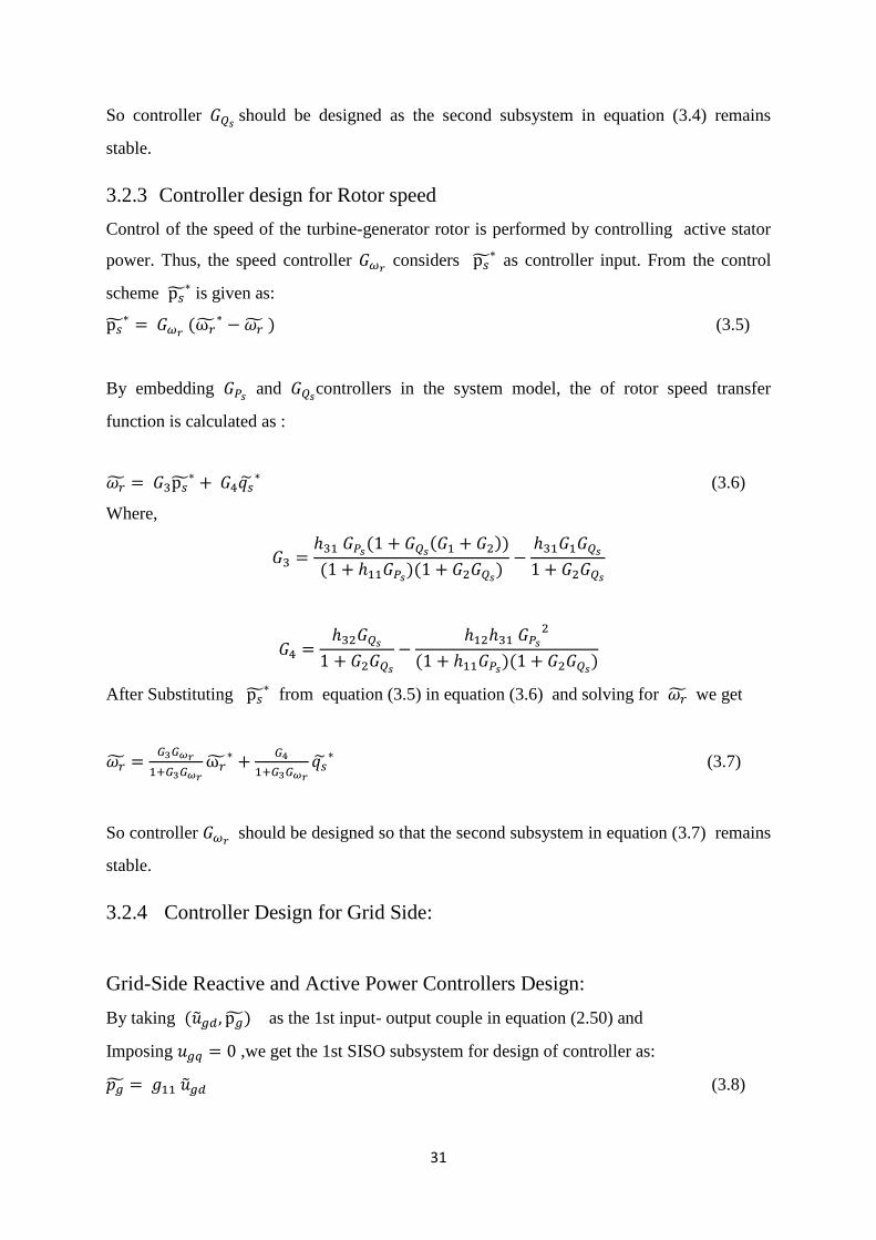
3.2.3 Controller design for Rotor speed
Control of the speed of the turbine-generator rotor is performed by controlling active stator
power. Thus, the speed controller considers as controller input. From the control
scheme is given as:
(
) (3.5)
By embedding and controllers in the system model, the of rotor speed transfer
function is calculated as :
(3.6)
Where,
( ( ))
( )( )
( )( )
After Substituting from equation (3.5) in equation (3.6) and solving for we get
(3.7)
So controller should be designed so that the second subsystem in equation (3.7) remains
stable.
3.2.4 Controller Design for Grid Side:
Grid-Side Reactive and Active Power Controllers Design:
By taking ( ) as the 1st input- output couple in equation (2.50) and
Imposing ,we get the 1st SISO subsystem for design of controller as:
(3.8)
32
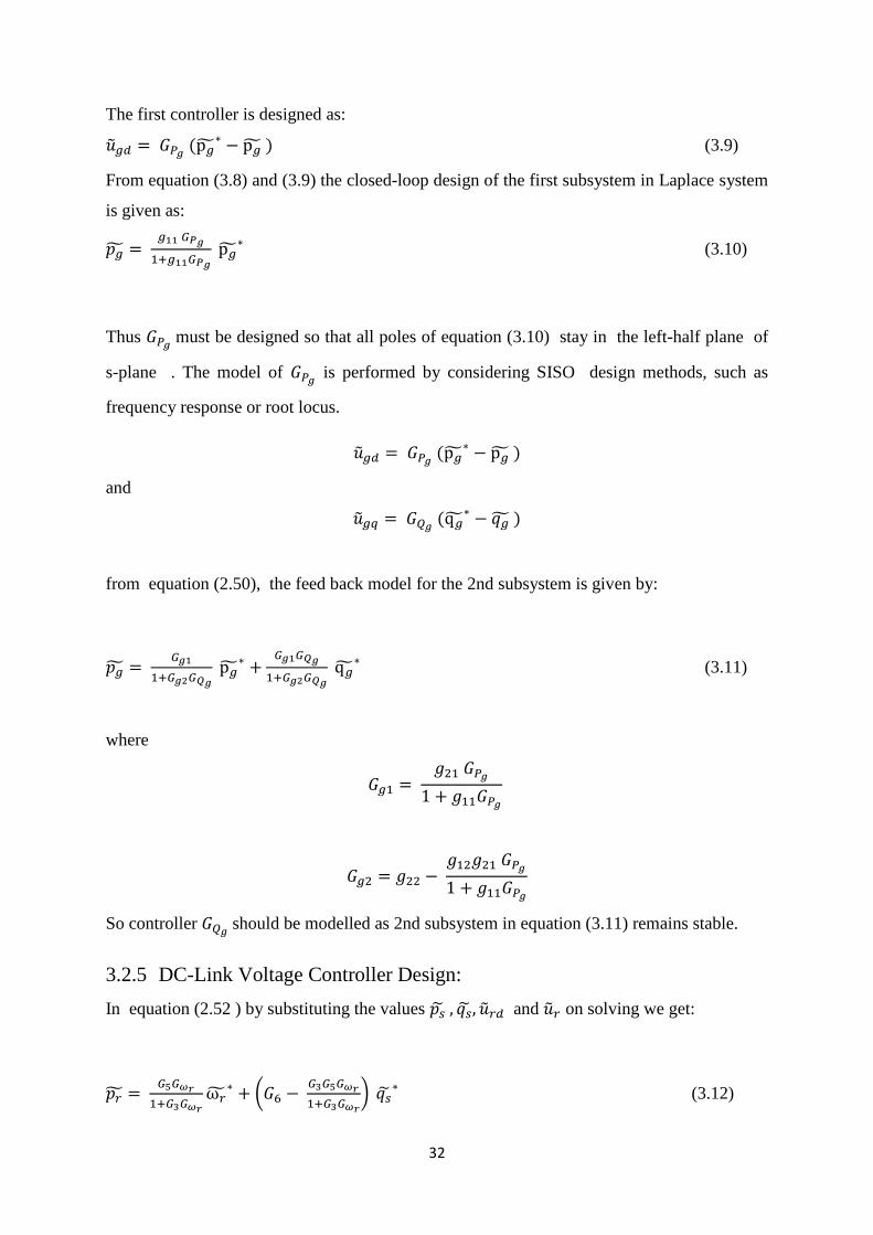
The first controller is designed as:
( ) (3.9)
From equation (3.8) and (3.9) the closed-loop design of the first subsystem in Laplace system
is given as:
(3.10)
Thus must be designed so that all poles of equation (3.10) stay in the left-half plane of
s-plane . The model of is performed by considering SISO design methods, such as
frequency response or root locus.
( )
and
( )
from equation (2.50), the feed back model for the 2nd subsystem is given by:
(3.11)
where
So controller should be modelled as 2nd subsystem in equation (3.11) remains stable.
3.2.5 DC-Link Voltage Controller Design:
In equation (2.52 ) by substituting the values and on solving we get:
(
) (3.12)
33
In the system, controls at its reference value controlling the dc-link controller as :
(
)
Therefore, from equation (2.53) and (3.5) , the feed back system for is shown as :
( ( ))
( )( ) (3.13)
Where
( )
( )( ( ) )
( )( )
( )
( )( ) ( )
( ) (
)
( )
So controller should be modelled as 2nd
subsystem in equation (3.13) remains stable.
3.3 Calculation of control Parameters
The system has been aconsidered as a 1.5-MW DFIG wind turbine-power source connected
to grid. Using the described design method, the controllers are designed for the system
developed are given :
(
) (
)
(
) (
)
(
)
34
(
)
(
) (
)
35
CHAPTER-4
SIMULATIONS AND RESULTS
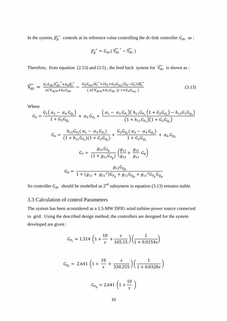
4.1 Design of Wind turbine
For a particular wind speed, power extraction from turbine will be maximum if the Cp will be
maximum. For optimum value, the value of Cp will be maximum for a particular TSR value.
With increased value of Pitch angle (ß), the Cp decreases with increase in pitch angle with
increasing TSR. The power output vs wind speed is also studied. The plot for Cp vs TSR is
by varing the pitch angle to 0,4 and 6.
Fig.4.1(a) Power coefficient Vs Tip speed ratio characterstics
0 1 2 3 4 5 6 7 80
0.05
0.1
0.15
0.2
0.25
0.3
0.35
0.4
0.45
tip speed ratio
pow
er
coeff
icie
nt
Power coefficient(Cp) Vs Tip speed ratio
36
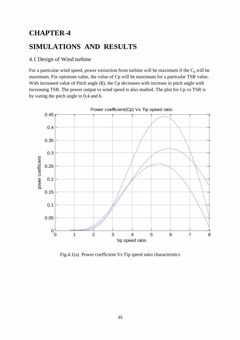
Fig 4.1(b)- Power output of turbine Vs Wind speed characteristics
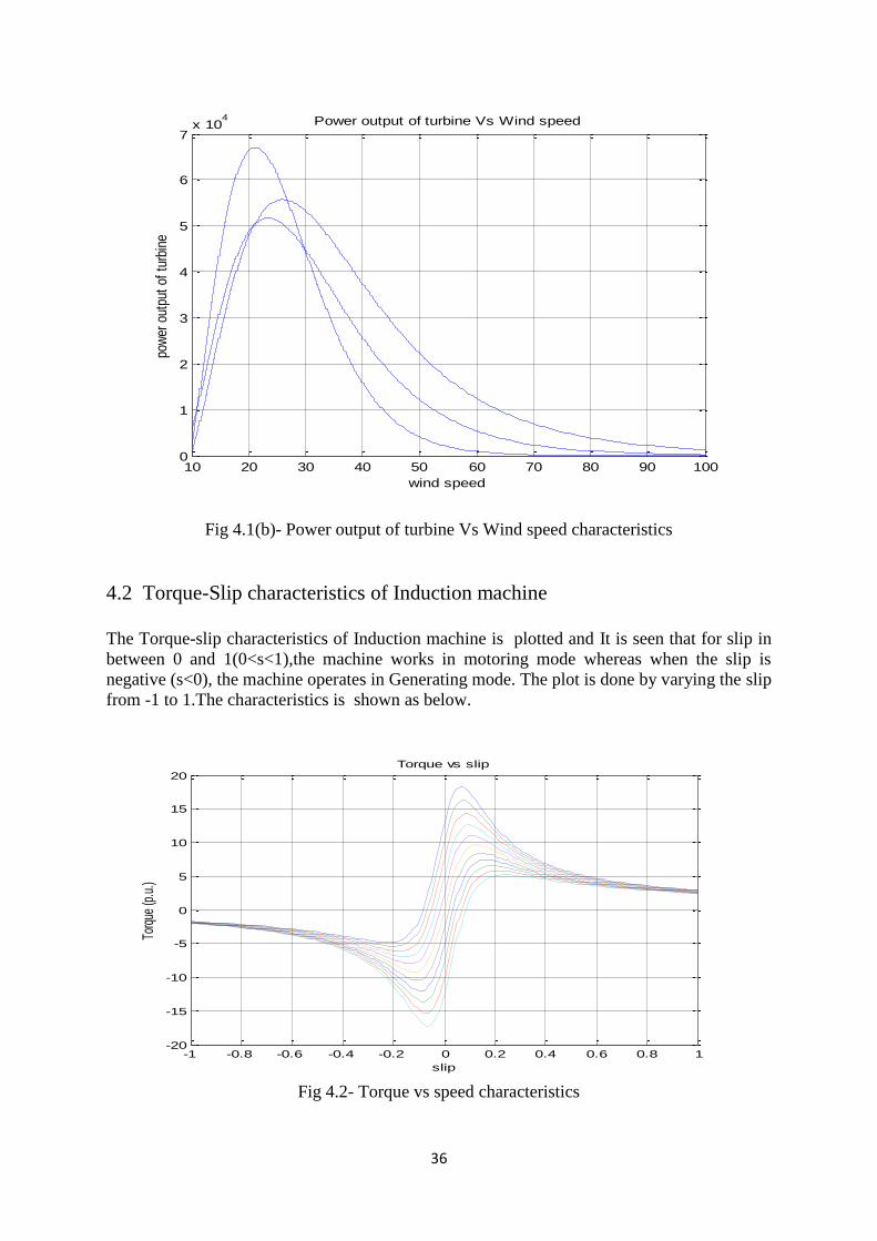
4.2 Torque-Slip characteristics of Induction machine
The Torque-slip characteristics of Induction machine is plotted and It is seen that for slip in
between 0 and 1(0<s<1),the machine works in motoring mode whereas when the slip is
negative (s<0), the machine operates in Generating mode. The plot is done by varying the slip
from -1 to 1.The characteristics is shown as below.
Fig 4.2- Torque vs speed characteristics
10 20 30 40 50 60 70 80 90 1000
1
2
3
4
5
6
7x 10
4
wind speed
pow
er o
utpu
t of
tur
bine
Power output of turbine Vs Wind speed
-1 -0.8 -0.6 -0.4 -0.2 0 0.2 0.4 0.6 0.8 1-20
-15
-10
-5
0
5
10
15
20
slip
Torq
ue (p
.u.)
Torque vs slip
37
4.3 SIMULINK FOR CONTROLLING OF DFIG-
By applying Three phase supply to the machine through grid and after changing the variables
to dq0 reference variables, and the plots for stator, rotor powers are plotted as below.
Fig.4.3 Simulink Block Diagram for controlling of DFIG