Modelling Mesh Independent Transverse Cracks inLaminated Composites with a Simplified Cohesive
Segment Method
Luiz F. Kawashita1, Alexandre Bedos2 and Stephen R. Hallett3
Abstract: A methodology is proposed for modelling transverse matrix cracks inlaminated composites in a three-dimensional explicit finite element analysis frame-work. The method is based on the introduction of extra degrees of freedom to rep-resent the displacement discontinuity and the use of a cohesive zone model to deter-mine damage evolution and crack propagation. The model is designed for the anal-ysis of matrix cracks in laminates made of uni-directional fibre-reinforced plies, al-lowing several assumptions to be made which greatly simplify the algorithm. Thiswas implemented in the commercial software Abaqus/Explicit as a user-defined el-ement subroutine (VUEL). The methodology was verified via the analysis of open-hole tension tests considering both ±45˚ and quasi-isotropic layups. The resultswere found to be in qualitative agreement with experimental observations in termsof the nucleation and propagation of matrix cracks, the progressive delaminationbehaviour and the evident interactions between these damage mechanisms.
Carbon-fibre reinforced composites manufactured from uni-directional plies are be-coming the material of choice for large structural components in aerospace appli-cations. The failure of these materials under quasi-static or impact overloading ishighly complex and usually involves a combination of three damage mechanisms,namely delamination, transverse cracking and fibre failure [Green et al. (2007),
1 School of Engineering, Cardiff University, Cardiff CF24 3AA, Wales, UK. Email:[email protected]
2 Eole Nationale Supeieure des Mines de Saint-Eienne, F-42023 Saint Eienne, France.3 Advanced Composites Centre for Innovation and Science (ACCIS), University of Bristol, Bristol
Hallett et al (2009)]. In order to achieve optimal designs in terms of weight reduc-tion, damage tolerance and extended service life the progressive damage behaviourof the material must be predicted with accuracy. The interactions between the dif-ferent damage mechanisms can be very complex and difficult to model using analyt-ical or numerical methods. For this reason much of the design of high-performancecomposite structures still relies on large amounts of experimental testing which areboth costly and time-consuming.
In many cases an accurate analysis of the progressive failure of composites requiresthe use of fracture mechanics considerations. The ability to model fracture pro-cesses within the finite element analysis framework has improved considerably af-ter the introduction of robust numerical tools such as the virtual crack closure tech-nique (VCCT) [Rybricki and Kanninen (1977)] and cohesive zone models (CZM)implemented in the form of interface elements [e.g. Alfano and Crisfield (2001),Camanho et al. (2003), Yang and Cox (2005), Pinho et al. (2006), Jiang et al.(2007)]. However, a major drawback of these methods is that they require a prioriknowledge of the possible paths of each crack. This is not a significant problem fordelamination which always occurs along well defined inter-ply interfaces; howeverit is difficult to pre-determine the locations of intra-ply transverse matrix cracks.Including these cracks in the finite element mesh additionally makes it extremelycomplex and too costly for practical industrial use. It has however been shown thatinteraction between matrix cracks and delamination has a critical part to play indetermining the overall failure process [Green et al. (2007), Hallett et al. (2009)].
It is possible to model cracks and other discontinuities independently of the meshdefinition via the introduction of enrichment functions in the finite element ap-proximation. The extended finite element method (XFEM) [Belytschko and Black(1999)], which makes use of the partition of unity property of finite element shapefunctions [Melenk and Babuska (1996)], has been studied extensively in the pastdecade for various problems involving static or moving discontinuities [Fries andBelytschko (2010)]. Several variants and further developments have also been pro-posed, and of particular relevance are the consideration of cohesive cracks [Wellsand Sluys (2001), Möes and Belytschko (2002)], the description of the discontinu-ity using phantom nodes [Hansbo and Hansbo (2004), Song et al. (2006), van derMeer and Sluys (2009)], the analysis of multiple overlapping cohesive segments[Remmers et al. (2003)] and the analysis of dynamic crack growth [Menouillard etal. (2006), Song et al. (2008), Nistor et al. (2008), Remmers et al. (2008)]. Al-though a number of codes have been developed for academic purposes, commercialimplementations of XFEM are still in their infancy and may lack the robustness tosolve problems involving multiple cracks in complex structures.
The aim of the present work was to develop and implement a simple and effec-
Modelling Mesh Independent Transverse Cracks 135
tive algorithm for the analysis of mesh-independent transverse cracks in laminatedcomposites. This was intended to be a high-fidelity modelling tool for ply-levelmodels solved using explicit time-integration schemes. The use of explicit finiteelement analysis has been found to be greatly beneficial in overcoming conver-gence difficulties of implicit analyses in the case of highly non-linear and unstablecomposites failure, even when loading is quasi-static [Jiang et al. (2007), Hal-lett et al. (2009), Kawashita and Hallett (2012)]. Particular emphasis was placedon numerical robustness so that the technique could be applied in the analysis ofrealistic composite structures typical of aerospace applications. The formulationpresented here was specifically designed to model laminates made from unidirec-tional plies. Therefore several assumptions could be made which greatly simplifiedits implementation, enabling its introduction in the commercial finite element soft-ware Abaqus/Explicit by means of a user-defined element subroutine.
The model presented here is the result of an effort to develop a practical methodfor modelling transverse cohesive cracks in ply-level meshes using explicit finiteelement software. The main aim was to replace the use of pre-defined crack pathsadopted in previous work [e.g. Jiang et al. (2007), Hallett et al (2009)] with mesh-independent cohesive cracks that followed a similar set of assumptions.
It should be noted that there is a large body of literature on the analysis of strongdiscontinuities and discrete cohesive cracks in finite element models. Relevant pa-pers include Song et al. (2006), van der Meer and Sluys (2009), Armero and Linder(2009) among others. The model proposed here presents however a combinationof features that results in great simplicity in terms of its implementation, whichtranslates into numerical robustness and the ability to analyse large realistic prob-lems. These features include (i) a series of simplifying assumptions suitable for theanalysis of laminates, (ii) the use of an explicit solver, and (iii) the compatibility ofthe code with user-defined element subroutines found in commercial finite elementsoftware.
The next section describes in detail the characteristics of the algorithm and themain assumptions made. In Section 3 test cases are analysed which demonstratethe ability of the model to predict the initiation and propagation of multiple matrixcracks.
2 Model formulation
2.1 Element formulation
The baseline formulation for ‘undamaged’ elements is the 8-node fully-integratedlinear isoparametric hexahedral element. Once a discontinuity is introduced, thedomain is sub-divided using linear pentahedral elements as will be discussed later.
A linear-elastic orthotropic constitutive law is used to model the fibre-reinforcedplies. However, in order to allow future developments of the code (e.g. the imple-mentation of continuum damage models and rate-dependent material behaviour),the constitutive law has been written in terms of an objective stress rate, whichalso makes the user-defined elements consistent with the elements provided inAbaqus/Explicit. The stress rate is based on the rate-of-deformation tensor D andthe spin tensor W,
D =12(LT +L
), and W =
12(L−LT ) , (1)
where L is the velocity gradient. The constitutive law is then written in rate formbased on the Jaumman stress rate given by,
σ̇σσ = C : D+W ·σσσ +σσσ ·WT , (2)
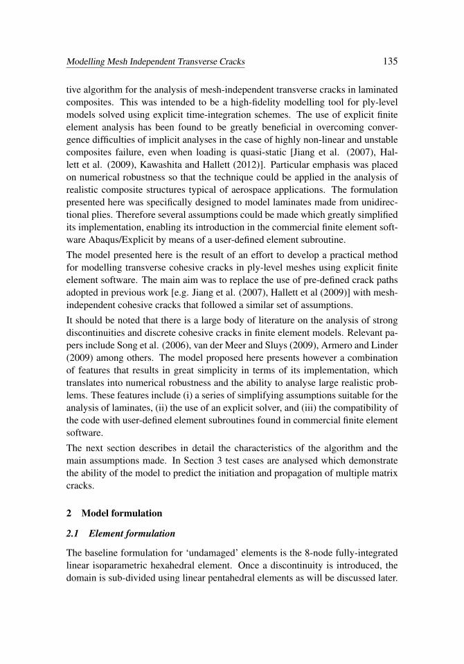
where C is the material stiffness matrix. When evaluating the constitutive equation,a full Gauss quadrature is used as depicted in Figure 1a (which shows a planarrepresentation of the 3D elements).
original nodesextra nodesintegration points
(a) (b)
Figure 1: Planar representation of a fully-integrated 3D hexahedral element (a)which is split into pentahedral sub-domains with the introduction of extra nodes(b).
2.2 Displacement discontinuity and extra nodes
When the element is ‘damaged’ a strong discontinuity is introduced so that twoindependent displacement fields exist. To resolve the displacement jump betweenthese fields, eight ‘extra’ nodes are introduced as shown in Figure 1b. These nodesare initialised as four coincident pairs so that the initial displacement jump acrossthe discontinuity is zero. Their initial displacements and velocities are obtainedby linear interpolation of nodal values from the original hexahedral element. For
Modelling Mesh Independent Transverse Cracks 137
example, the velocities of a new node located at the parametric coordinates ξξξ areinitialised by,
v(ξξξ ) =8
∑n=1
Nn(ξξξ ) vn, (3)
where Nn are the standard shape functions of the original isoparametric elementand vn are the velocities at the original nodes. Because the extra nodes are initiallypositioned along an edge of the original element, equation (3) simplifies to a linearinterpolation between two nodes only.
In order to consider the two displacement fields independently a change is requiredfrom the original integration scheme. The hexahedral element is therefore ‘trian-gulated’ into multiple pentahedral sub-domains with two integration points each(which appear as one in the top view of Figure 1b). Stresses and other statevariables are projected onto the new integration points using the same standardshape functions Nn. This requires the use of modified parametric coordinates ξ̄ξξ
in the range ξ̄i ∈[−√
3,√
3]
so that the coordinates of the original Gauss pointsξi =±1/
√3 become ξ̄i =±1. For example, the stresses at a new integration point
with coordinates ξ̄ξξ are given by,
σσσ
(ξ̄ξξ
)=
8
∑n=1
Nn
(ξ̄ξξ
)σσσn, (4)
where σσσn are the stresses at the original Gauss points.
Once the element has been divided into sub-domains and the new nodes and inte-gration points have been initialised, the element operations (interpolation of fieldvariables, evaluation of the constitutive equation and integration of internal forces)are then performed for every sub-domain independently using the appropriate shapefunctions for the linear pentahedral element.
The code is structured to cope with changes in the interpolation and integrationschemes with minimal disruption to the solution. This is also facilitated by the‘element-by-element’ nature of the explicit solution algorithm which does not re-quire the assembly of global matrices. At the start of the simulation enough mem-ory is allocated for each element taking into account the maximum number of inte-gration points and extra nodes that could be required upon fracturing. The elementcomputations are coded in a way that allows for simple looping over multiple sub-domains of either hexahedral or pentahedral formulation. Although the initialisa-tion of new nodes and integration points require a number of additional operations,they are performed only once when an element fractures. After that, two pentahe-dral sub-domains will have roughly the same computational cost of one hexahedral
element for interpolation and integration. However further computational costs willincur with the introduction of a cohesive segment as described next.
2.3 Cohesive law
Damage evolution and crack propagation are determined using a cohesive zonemodelling (CZM) approach. This method avoids the need for treating singularor oscillatory stress fields that appear in linear elastic analyses because the grad-ual softening behaviour of the interface ensures finite tractions within the cohesivezone. It is also a proven modelling tool for analysing composites delamination andfracture [Petrossian and Wisnom (1998), Alfano and Crisfeld (2001), Camanho etal. (2003), Yang and Cox (2005)] and is particularly robust when using explicittime-integration [Pinho et al. (2006), Jiang et al. (2007)]. The main disadvantageof CZM is the requirement for good resolution of the cohesive zone ahead of thecrack tip, which means that relatively fine meshes are usually needed for accuracy[Turon et al. (2007), Harper and Hallett (2008)].
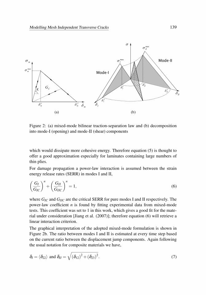
The eight extra nodes added to each fractured element form a quadrilateral cohe-sive segment where the displacement jump is interpolated linearly. Here a singlecohesive integration point is used for simplicity, as this has been shown to be accu-rate in practical applications [Hallett et al. (2009)]. The mixed-mode formulationpresented by Jiang et al. (2007) is employed, and the reader should refer to thatarticle for further details about the model. Traction-separation laws of linear soft-ening are assumed as shown in Figure 2a. The subscripts I and II refer to mode-I(opening) and resultant mode-II (shear) respectively, while the subscript m denotesan arbitrary mode-mixity. The superscripts e and f refer to the critical separationsat the elastic limit and failure, respectively.
To initiate fracture a quadratic criterion is used, i.e.√√√√√(〈σ22〉σmax
I
)2
+
√
(σ12)2 +(σ23)
2
σmaxII
2
= 1, (5)
where the numerical indices follow the usual notation for composite materials (1for the fibre direction and 3 for the out-of-plane direction), σmax
I and σmaxII are
the cohesive strengths in mode-I and mode-II, respectively, and 〈•〉 denotes theMcCauley operator. It should be noted that equation (5) is based on the assumptionthat the transverse crack is orthogonal to the plane 1-2 of the material. In reality, thepresence of transverse shear stresses σ23 may cause the transverse crack to initiateat a different angle with respect to the plane 1-2. This could require lower resultantshear stresses for crack initiation, however it would also produce larger crack areas
Modelling Mesh Independent Transverse Cracks 139
m
maxm
m
em
CG
fm
K
I
II
maxII
maxI
fI
fII
eIIe
I
Mode-I
Mode-II
(a) (b)
Figure 2: (a) mixed-mode bilinear traction-separation law and (b) decompositioninto mode-I (opening) and mode-II (shear) components
which would dissipate more cohesive energy. Therefore equation (5) is thought tooffer a good approximation especially for laminates containing large numbers ofthin plies.
For damage propagation a power-law interaction is assumed between the strainenergy release rates (SERR) in modes I and II,(
GI
GIC
)n
+(
GII
GIIC
)n
= 1, (6)
where GIC and GIIC are the critical SERR for pure modes I and II respectively. Thepower-law coefficient n is found by fitting experimental data from mixed-modetests. This coefficient was set to 1 in this work, which gives a good fit for the mate-rial under consideration [Jiang et al. (2007)]; therefore equation (6) will retrieve alinear interaction criterion.
The graphical interpretation of the adopted mixed-mode formulation is shown inFigure 2b. The ratio between modes I and II is estimated at every time step basedon the current ratio between the displacement jump components. Again followingthe usual notation for composite materials we have,
Overclosure of the crack surfaces is minimised with the enforcement of a constantpenalty stiffness of magnitude KI which opposes the interpenetration of the surfaceswhen δI is negative. Frictionless contact is assumed throughout.
When a cohesive segment is introduced in a pristine element, the initial displace-ment jump must be zero while the initial cohesive tractions must match the localstress state. Therefore, the use of a cohesive law of finite stiffness requires thetraction-separation curve, Figure 2a, to be ‘shifted’ to the left so that the maxi-mum traction occurs at zero separation [van der Meer et al. (2012)]. This shifteddisplacement jump is defined as,
δ̃ = δ −δe, (8)
which applies to both modes of loading (I and II).
Equation (8) shows that if the stresses in the vicinity of an active cohesive segmentare relaxed the interface will acquire a residual displacement jump of −δe. Thismeans that a small permanent deformation is introduced locally whenever a new acohesive segment is initialised, with its magnitude being inversely proportional tothe assumed cohesive stiffness. Although this residual deformation is unwanted, itseffects will be minor and only observable if active cohesive segments are unloadedprior to failure. Therefore this effect will be negligible when compared for examplewith the global stiffness change that is introduced when potential cracks are meshedusing cohesive elements.
2.4 Time-integration scheme
The extra nodes introduced when an element splits are not accessible to the Abaqus/Explicitsolver and therefore must be managed and updated inside the user sub-routine. Fol-lowing the assembly of the internal force vector, the extra nodes are updated via amodified central difference rule. At a given time increment k, the half-step veloci-ties are obtained via,
uk+1/2 = uk−1/2 +∆tk−1/2 +∆tk−1/2
2(M−1finf), (9)
where M is the diagonal mass matrix, ∆t is the time step size and fint is the internalforce vector. The nodal displacements for the increment k +1 are then given by,
uk+1 = uk +∆tk+1/2 u̇k+1/2. (10)
The splitting of elements and the introduction of cohesive segments may generatelocal stress imbalances that can result in high-frequency ‘noise’ in the dynamic so-lution. Depending on the amplitude of these oscillations and the size of the newly
Modelling Mesh Independent Transverse Cracks 141
created sub-domains numerical instabilities can arise. Therefore an optional vis-cous damping term c is defined so that the velocity update for extra nodes becomes,
u̇k+1/2 = u̇k−1/2 +∆tk−1/2 +∆tk+1/2
2[M−1 (fint − c u̇k+1/2
)]. (11)
It should be noted that viscous damping will reduce the stable time increment andmay generate spurious forces under rigid body motion, so this parameter should beused with caution. In the present work, and when necessary, appropriate values forc were determined ‘empirically’ by performing series of simulations, starting withc= 0 and increasing this value until the numerical instability was overcome.
All the results presented in this paper have been analysed using a range of valuesfor the mass scaling and viscous damping parameters to verify the sensitivity ofthe results to these values. It has been observed that the peak loads and patternsof matrix cracks and delaminations are relatively insensitive to these parameters aslong as the dynamic effects are negligible, as measured e.g. by the ratio betweenthe amplitudes of the introduced vibrations with respect to the monotonic (‘quasi-static’) deformations, and the ratio between the kinetic and internal energies. Thishas confirmed previous observations using pre-defined crack paths, e.g. in Jiang etal. (2007) and Hallett et al. (2009).
2.5 Orientation and continuity of crack paths
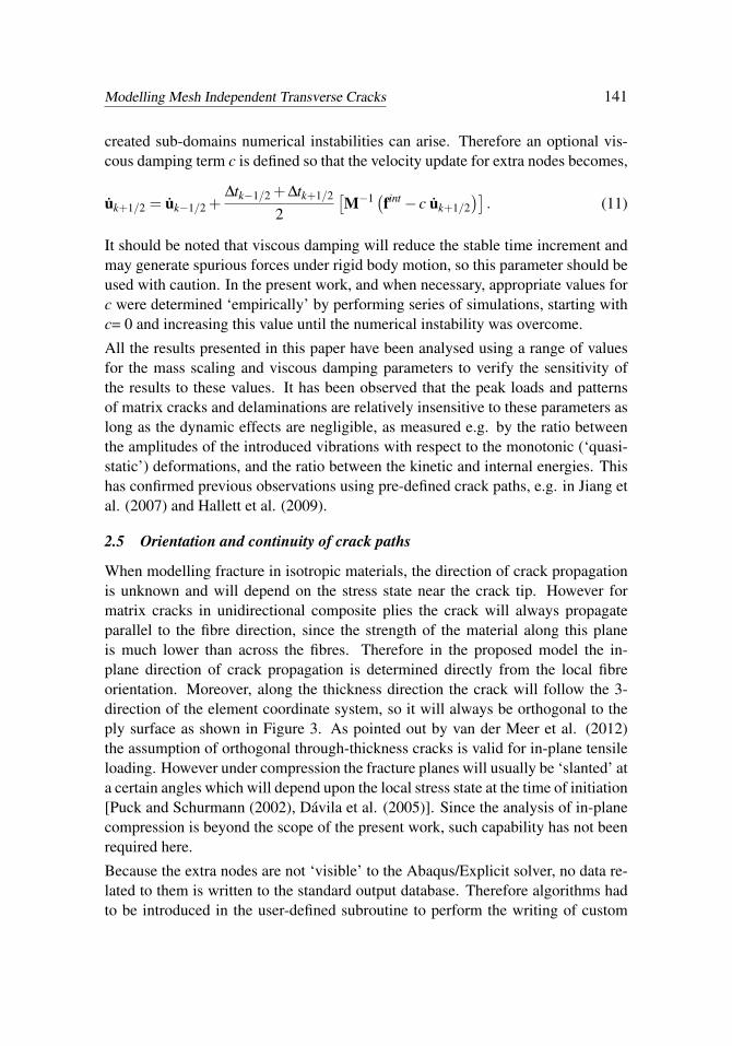
When modelling fracture in isotropic materials, the direction of crack propagationis unknown and will depend on the stress state near the crack tip. However formatrix cracks in unidirectional composite plies the crack will always propagateparallel to the fibre direction, since the strength of the material along this planeis much lower than across the fibres. Therefore in the proposed model the in-plane direction of crack propagation is determined directly from the local fibreorientation. Moreover, along the thickness direction the crack will follow the 3-direction of the element coordinate system, so it will always be orthogonal to theply surface as shown in Figure 3. As pointed out by van der Meer et al. (2012)the assumption of orthogonal through-thickness cracks is valid for in-plane tensileloading. However under compression the fracture planes will usually be ‘slanted’ ata certain angles which will depend upon the local stress state at the time of initiation[Puck and Schurmann (2002), Dávila et al. (2005)]. Since the analysis of in-planecompression is beyond the scope of the present work, such capability has not beenrequired here.
Because the extra nodes are not ‘visible’ to the Abaqus/Explicit solver, no data re-lated to them is written to the standard output database. Therefore algorithms hadto be introduced in the user-defined subroutine to perform the writing of custom
Figure 3: Crack propagation in a 60˚ off-axis tensile test, (a) original mesh and (b)after the nucleation and propagation of a solution-dependent crack
data files at regular time intervals. These files contained various types of data in-cluding the coordinates of original and extra nodes, stress and strain components,state variables etc. Generic visualisation software could then be used to access,visualise and manipulate these data.
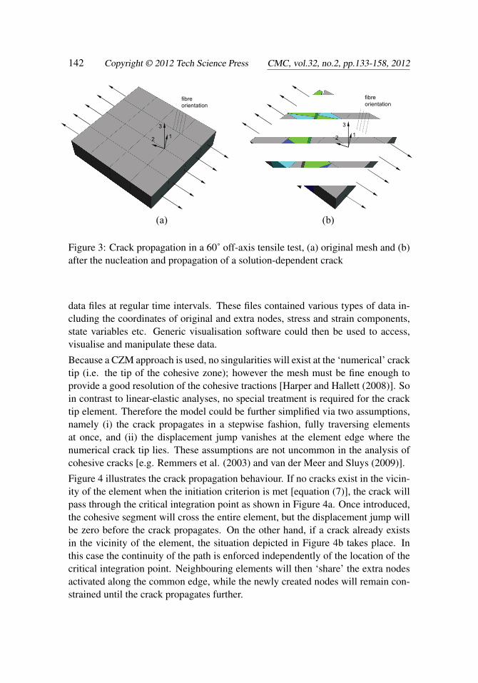
Because a CZM approach is used, no singularities will exist at the ‘numerical’ cracktip (i.e. the tip of the cohesive zone); however the mesh must be fine enough toprovide a good resolution of the cohesive tractions [Harper and Hallett (2008)]. Soin contrast to linear-elastic analyses, no special treatment is required for the cracktip element. Therefore the model could be further simplified via two assumptions,namely (i) the crack propagates in a stepwise fashion, fully traversing elementsat once, and (ii) the displacement jump vanishes at the element edge where thenumerical crack tip lies. These assumptions are not uncommon in the analysis ofcohesive cracks [e.g. Remmers et al. (2003) and van der Meer and Sluys (2009)].
Figure 4 illustrates the crack propagation behaviour. If no cracks exist in the vicin-ity of the element when the initiation criterion is met [equation (7)], the crack willpass through the critical integration point as shown in Figure 4a. Once introduced,the cohesive segment will cross the entire element, but the displacement jump willbe zero before the crack propagates. On the other hand, if a crack already existsin the vicinity of the element, the situation depicted in Figure 4b takes place. Inthis case the continuity of the path is enforced independently of the location of thecritical integration point. Neighbouring elements will then ‘share’ the extra nodesactivated along the common edge, while the newly created nodes will remain con-strained until the crack propagates further.
Modelling Mesh Independent Transverse Cracks 143
criterion met new cohesive segment
fibre direction
original nodes
active extra nodesintegration pointscriterion met
pre-existing crack
(a) Absence of a crack – intersect integration point
(b) Presence of a crack – ensure continuity of the crack path
new cohesive segment
constrained extra nodes
fibre direction
Figure 4: Introduction of a new cohesive segment within the element
2.6 Time-step considerations
Explicit schemes such as the central difference method utilised here are only con-ditionally stable, requiring the time increment size to be below a critical maximumto ensure numerical stability. This critical time increment is given by the Courantcriterion,
∆tcrit =lew
, (12)
where w is the speed of sound in the material and le is the smallest equivalentelement length in the direction of wave propagation. Because the ply thickness isconstant, the element lengths in the 3-direction will usually be constant (in ply-levelmodels). Moreover, if the mesh is of good quality then the in-plane aspect ratio ofthe elements will be close to 1. Following these assumptions, equation (12) may beapproximated as,
∆t̄crit =√
Aρ
E11, (13)
where ρ is the material density, E11 is the elastic modulus in the fibre direction,and A is the in-plane area of the smallest integration sub-domain in the model.Equation (13) shows that as the integration volume approaches zero the critical
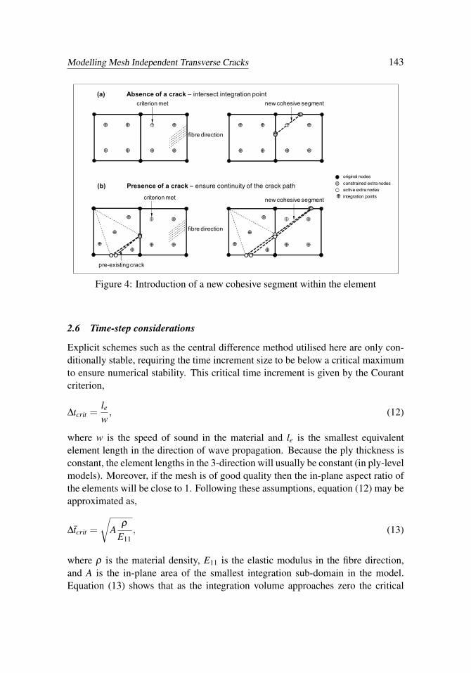
stable increment vanishes. Therefore in order to avoid extremely small time steps(and consequently extremely expensive solutions) some level of control is requiredover the sub-domain size. In the proposed model this control is achieved via thedefinition of a single scalar safety factor α , so that the minimum sub-domain lengthis set to be L α , where L is the characteristic length of the original (parent) element.This concept is illustrated in Figure 5, again using a planar representation of 3Delements. In this example, because the mesh is structured and the element size isconstant, the length L α can be seen as a critical radius surrounding every node. Ifthe predicted path of a propagating crack (dashed line) intersects an element edgeat a distance smaller than L α , two options exist. If the distance is greater thanor equal L α/2, the intersection point is moved away from the node to enforce aminimum sub-domain size, as shown by the solid line in Figure 5a (an example ofthis can be seen in Figure 3b). However, if the distance is smaller than L α/2, thecrack is set to pass exactly through that node, Figure 5b. It should be noted thatmany other patterns of crack propagation deriving from these assumptions are alsotaken into account, including cracks running along element boundaries, elementsbeing split exactly into two pentahedrals, etc.
L
Radius L·
Radius L·
L
Propagating crack
Ideal pathModified path
Propagating crack
Radius L·
Radius L·
(a) (b)
Figure 5: Changes to the crack path for time-step considerations; (a) enforcing aminimum sub-domain size or (b) intersecting a node.
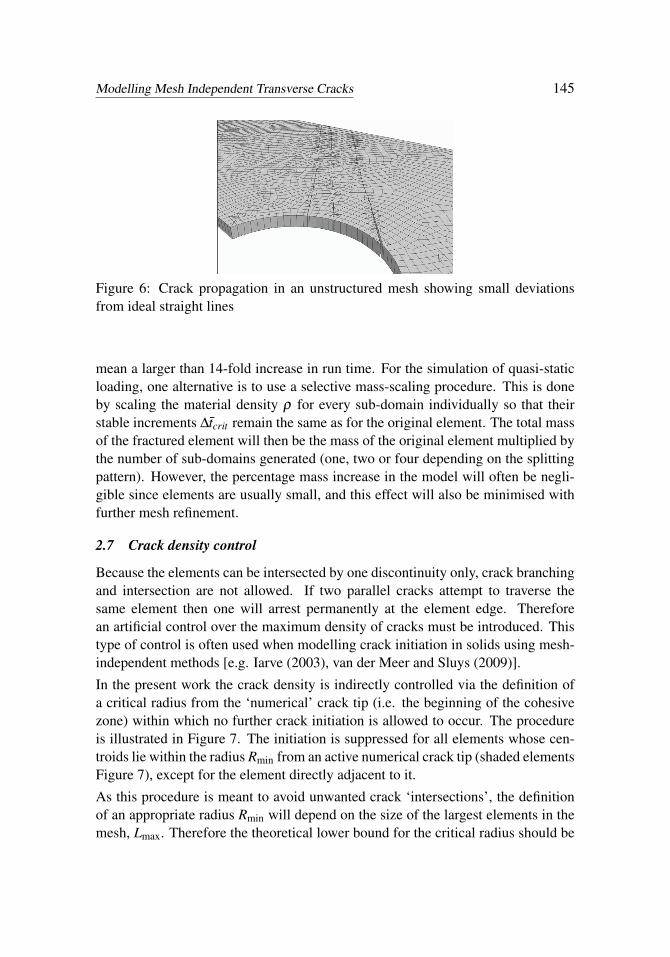
In the present work the value of α= 0.1 has been assumed throughout. Figure 6shows an example of crack propagation in an unstructured mesh using this value.It can be seen that the effective crack paths are not perfectly straight lines, howeverthe effects of such small deviations are thought to be negligible. Additionally,deviations are minimised as the mesh is further refined.
For α= 0.1, the value of A for the smallest sub-domain in Figure 5a is 200 timeslower than that for the original element. Therefore in this case the stable time in-crement ∆t̄crit would drop by a factor
√200 upon crack propagation, which would
Modelling Mesh Independent Transverse Cracks 145
Figure 6: Crack propagation in an unstructured mesh showing small deviationsfrom ideal straight lines
mean a larger than 14-fold increase in run time. For the simulation of quasi-staticloading, one alternative is to use a selective mass-scaling procedure. This is doneby scaling the material density ρ for every sub-domain individually so that theirstable increments ∆t̄crit remain the same as for the original element. The total massof the fractured element will then be the mass of the original element multiplied bythe number of sub-domains generated (one, two or four depending on the splittingpattern). However, the percentage mass increase in the model will often be negli-gible since elements are usually small, and this effect will also be minimised withfurther mesh refinement.
2.7 Crack density control
Because the elements can be intersected by one discontinuity only, crack branchingand intersection are not allowed. If two parallel cracks attempt to traverse thesame element then one will arrest permanently at the element edge. Thereforean artificial control over the maximum density of cracks must be introduced. Thistype of control is often used when modelling crack initiation in solids using mesh-independent methods [e.g. Iarve (2003), van der Meer and Sluys (2009)].
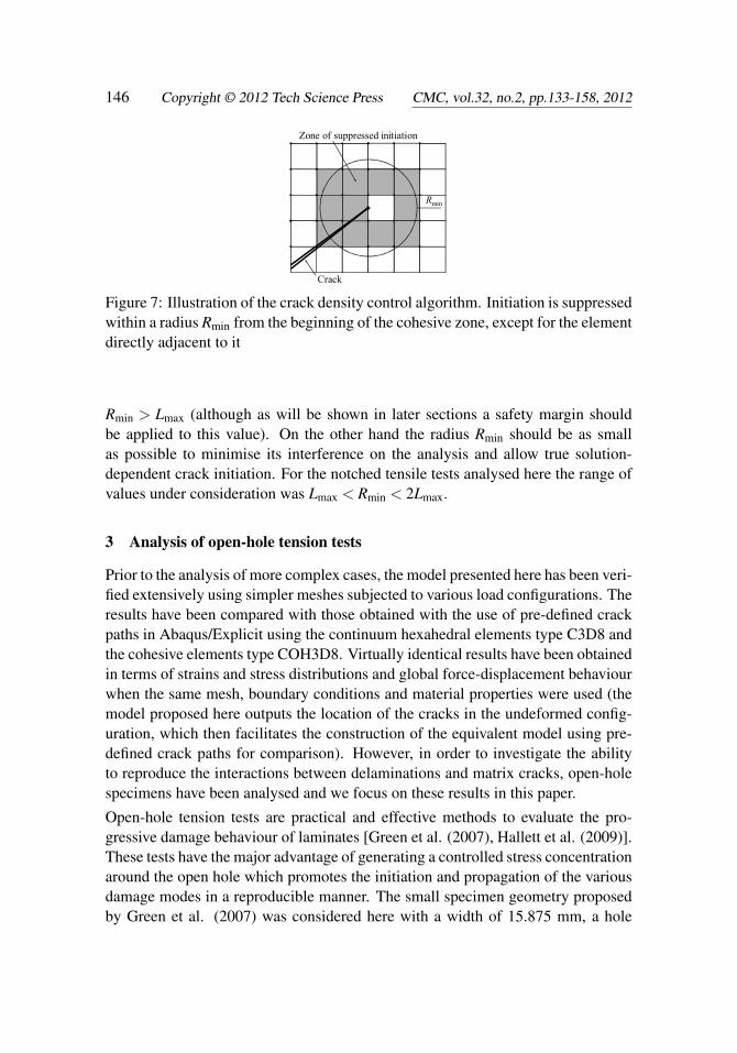
In the present work the crack density is indirectly controlled via the definition ofa critical radius from the ‘numerical’ crack tip (i.e. the beginning of the cohesivezone) within which no further crack initiation is allowed to occur. The procedureis illustrated in Figure 7. The initiation is suppressed for all elements whose cen-troids lie within the radius Rmin from an active numerical crack tip (shaded elementsFigure 7), except for the element directly adjacent to it.
As this procedure is meant to avoid unwanted crack ‘intersections’, the definitionof an appropriate radius Rmin will depend on the size of the largest elements in themesh, Lmax. Therefore the theoretical lower bound for the critical radius should be
Crack Figure 7: Illustration of the crack density control algorithm. Initiation is suppressedwithin a radius Rmin from the beginning of the cohesive zone, except for the elementdirectly adjacent to it
Rmin > Lmax (although as will be shown in later sections a safety margin shouldbe applied to this value). On the other hand the radius Rmin should be as smallas possible to minimise its interference on the analysis and allow true solution-dependent crack initiation. For the notched tensile tests analysed here the range ofvalues under consideration was Lmax < Rmin < 2Lmax.
3 Analysis of open-hole tension tests
Prior to the analysis of more complex cases, the model presented here has been veri-fied extensively using simpler meshes subjected to various load configurations. Theresults have been compared with those obtained with the use of pre-defined crackpaths in Abaqus/Explicit using the continuum hexahedral elements type C3D8 andthe cohesive elements type COH3D8. Virtually identical results have been obtainedin terms of strains and stress distributions and global force-displacement behaviourwhen the same mesh, boundary conditions and material properties were used (themodel proposed here outputs the location of the cracks in the undeformed config-uration, which then facilitates the construction of the equivalent model using pre-defined crack paths for comparison). However, in order to investigate the abilityto reproduce the interactions between delaminations and matrix cracks, open-holespecimens have been analysed and we focus on these results in this paper.
Open-hole tension tests are practical and effective methods to evaluate the pro-gressive damage behaviour of laminates [Green et al. (2007), Hallett et al. (2009)].These tests have the major advantage of generating a controlled stress concentrationaround the open hole which promotes the initiation and propagation of the variousdamage modes in a reproducible manner. The small specimen geometry proposedby Green et al. (2007) was considered here with a width of 15.875 mm, a hole
Modelling Mesh Independent Transverse Cracks 147
diameter of 3.175 mm and a gauge length of 63.5 mm (of which only the central31.75 mm are modelled in the finite element analysis). The material investigated inthis work is the Hexcel® IM7/8552 pre-preg system, and its basic mechanical prop-erties have been provided by Jiang et al. (2007) and are summarised in Tables 1 and2. The cohesive stiffnesses KI and KII in Table 2 were estimated from the isotropicmechanical properties of the resin system, i.e. a Young’s modulus E= 4.67 GPa andPoisson’s ratio ν= 0.33, assuming that the interfacial stiffness represents the elasticdeformation of a resin-rich layer of 0.01 mm in thickness [Kawashita and Hallett(2012)]. Two different layups were considered as described next.
Table 1: Elastic properties for unidirectional IM7/8552 laminates
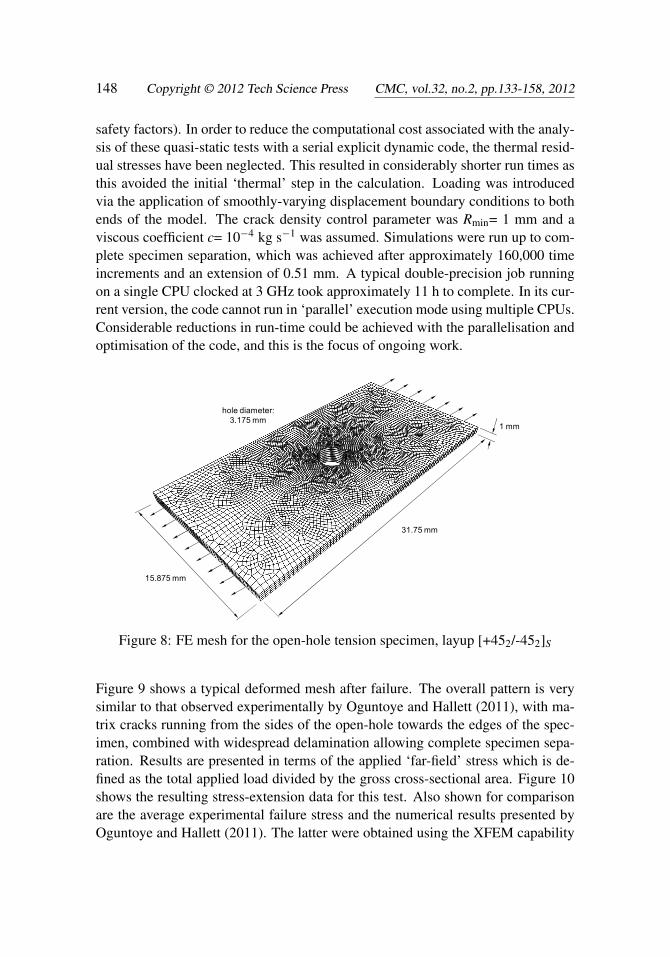
Open-hole tension tests using a symmetric [+452/-452]S layup have been proposedrecently as a benchmark for validating and comparing XFEM codes [Oguntoye andHallett (2011)]. The specimen dimensions and the adopted finite element mesh areshown in Figure 8. The cured ply thickness was 0.125 mm. Only a half-modelwas required due to the through-thickness symmetry. Each ply block (containingtwo plies) was meshed with one element through the thickness and modelled us-ing the proposed user-defined elements. The interface between the ply blocks wasmodelled using the cohesive elements COH3D8 provided by Abaqus/Explicit. Arather coarse mesh was used in this study with element sizes varying graduallyfrom 0.125 mm around the open-hole to 0.5 mm at the extremities. This resultedin 14,696 continuum elements, 7,348 cohesive elements and 30,032 nodes for thehalf-model. In order to analyse quasi-static loading with acceptable run times, aglobal mass-scaling procedure was used with a density scale factor of 105, resultingin a stable time increment of approximately 2×10⁻⁶ s (which includes appropriate
safety factors). In order to reduce the computational cost associated with the analy-sis of these quasi-static tests with a serial explicit dynamic code, the thermal resid-ual stresses have been neglected. This resulted in considerably shorter run times asthis avoided the initial ‘thermal’ step in the calculation. Loading was introducedvia the application of smoothly-varying displacement boundary conditions to bothends of the model. The crack density control parameter was Rmin= 1 mm and aviscous coefficient c= 10−4 kg s−1 was assumed. Simulations were run up to com-plete specimen separation, which was achieved after approximately 160,000 timeincrements and an extension of 0.51 mm. A typical double-precision job runningon a single CPU clocked at 3 GHz took approximately 11 h to complete. In its cur-rent version, the code cannot run in ‘parallel’ execution mode using multiple CPUs.Considerable reductions in run-time could be achieved with the parallelisation andoptimisation of the code, and this is the focus of ongoing work.
31.75 mm
15.875 mm
1 mm
hole diameter: 3.175 mm
Figure 8: FE mesh for the open-hole tension specimen, layup [+452/-452]S
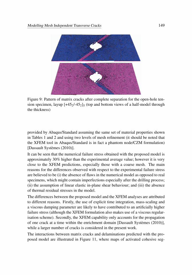
Figure 9 shows a typical deformed mesh after failure. The overall pattern is verysimilar to that observed experimentally by Oguntoye and Hallett (2011), with ma-trix cracks running from the sides of the open-hole towards the edges of the spec-imen, combined with widespread delamination allowing complete specimen sepa-ration. Results are presented in terms of the applied ‘far-field’ stress which is de-fined as the total applied load divided by the gross cross-sectional area. Figure 10shows the resulting stress-extension data for this test. Also shown for comparisonare the average experimental failure stress and the numerical results presented byOguntoye and Hallett (2011). The latter were obtained using the XFEM capability
Modelling Mesh Independent Transverse Cracks 149
Figure 9: Pattern of matrix cracks after complete separation for the open-hole ten-sion specimen, layup [+452/-452]S (top and bottom views of a half-model throughthe thickness)
provided by Abaqus/Standard assuming the same set of material properties shownin Tables 1 and 2 and using two levels of mesh refinement (it should be noted thatthe XFEM tool in Abaqus/Standard is in fact a phantom node/CZM formulation)[Dassault Systèmes (2010)].
It can be seen that the numerical failure stress obtained with the proposed model isapproximately 30% higher than the experimental average value; however it is veryclose to the XFEM predictions, especially those with a coarse mesh. The mainreasons for the differences observed with respect to the experimental failure stressare believed to be (i) the absence of flaws in the numerical model as opposed to realspecimens, which might contain imperfections especially after the drilling process;(ii) the assumption of linear elastic in-plane shear behaviour; and (iii) the absenceof thermal residual stresses in the model.
The differences between the proposed model and the XFEM analyses are attributedto different reasons. Firstly, the use of explicit time integration, mass-scaling anda viscous damping parameter are likely to have contributed to an artificially higherfailure stress (although the XFEM formulation also makes use of a viscous regular-isation scheme). Secondly, the XFEM capability only accounts for the propagationof one crack at a time within the enrichment domain [Dassault Systèmes (2010)],while a larger number of cracks is considered in the present work.
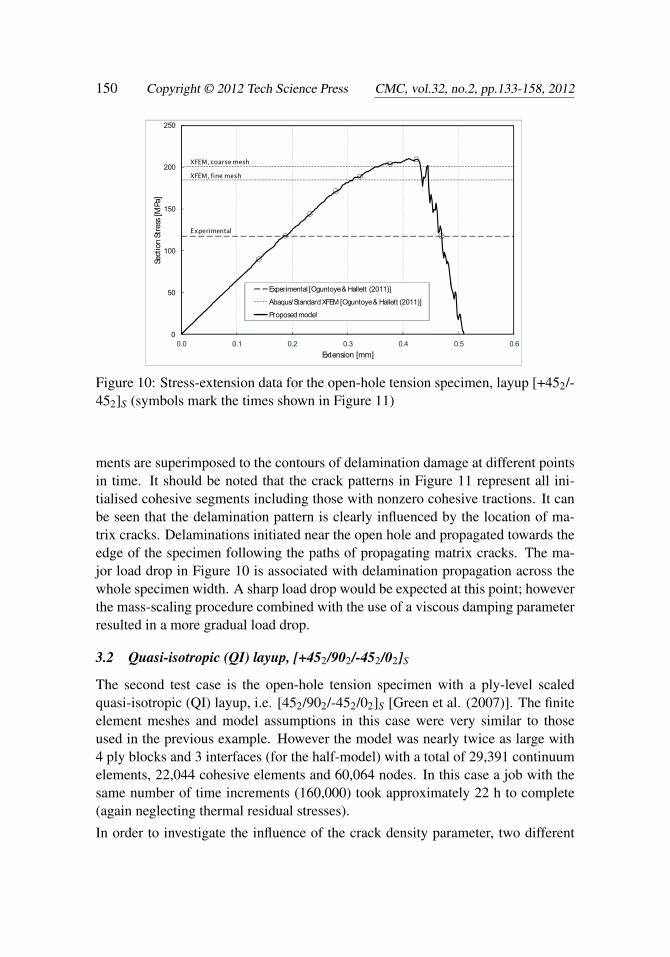
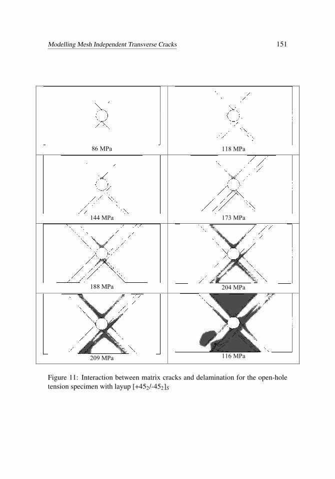
The interactions between matrix cracks and delaminations predicted with the pro-posed model are illustrated in Figure 11, where maps of activated cohesive seg-
Figure 10: Stress-extension data for the open-hole tension specimen, layup [+452/-452]S (symbols mark the times shown in Figure 11)
ments are superimposed to the contours of delamination damage at different pointsin time. It should be noted that the crack patterns in Figure 11 represent all ini-tialised cohesive segments including those with nonzero cohesive tractions. It canbe seen that the delamination pattern is clearly influenced by the location of ma-trix cracks. Delaminations initiated near the open hole and propagated towards theedge of the specimen following the paths of propagating matrix cracks. The ma-jor load drop in Figure 10 is associated with delamination propagation across thewhole specimen width. A sharp load drop would be expected at this point; howeverthe mass-scaling procedure combined with the use of a viscous damping parameterresulted in a more gradual load drop.
The second test case is the open-hole tension specimen with a ply-level scaledquasi-isotropic (QI) layup, i.e. [452/902/-452/02]S [Green et al. (2007)]. The finiteelement meshes and model assumptions in this case were very similar to thoseused in the previous example. However the model was nearly twice as large with4 ply blocks and 3 interfaces (for the half-model) with a total of 29,391 continuumelements, 22,044 cohesive elements and 60,064 nodes. In this case a job with thesame number of time increments (160,000) took approximately 22 h to complete(again neglecting thermal residual stresses).
In order to investigate the influence of the crack density parameter, two different
Modelling Mesh Independent Transverse Cracks 151
86 MPa
118 MPa
144 MPa
173 MPa
188 MPa
204 MPa
209 MPa
116 MPa
Figure 11: Interaction between matrix cracks and delamination for the open-holetension specimen with layup [+452/-452]S
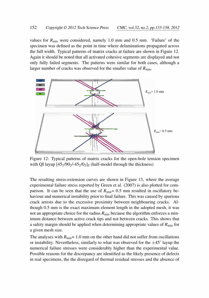
values for Rmin were considered, namely 1.0 mm and 0.5 mm. ‘Failure’ of thespecimen was defined as the point in time where delaminations propagated acrossthe full width. Typical patterns of matrix cracks at failure are shown in Figure 12.Again it should be noted that all activated cohesive segments are displayed and notonly fully failed segments. The patterns were similar for both cases, although alarger number of cracks was observed for the smaller value of Rmin.
0°
-45°
90°
+45°
Rmin= 1.0 mm
Rmin= 0.5 mm
Figure 12: Typical patterns of matrix cracks for the open-hole tension specimenwith QI layup [452/902/-452/02]S (half-model through the thickness)
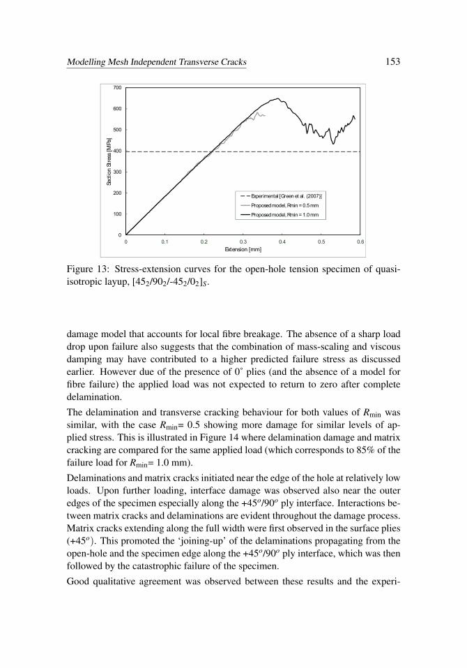
The resulting stress-extension curves are shown in Figure 13, where the averageexperimental failure stress reported by Green et al. (2007) is also plotted for com-parison. It can be seen that the use of Rmin= 0.5 mm resulted in oscillatory be-haviour and numerical instability prior to final failure. This was caused by spuriouscrack arrests due to the excessive proximity between neighbouring cracks. Al-though 0.5 mm is the exact maximum element length in the adopted mesh, it wasnot an appropriate choice for the radius Rmin because the algorithm enforces a min-imum distance between active crack tips and not between cracks. This shows thata safety margin should be applied when determining appropriate values of Rmin fora given mesh size.
The analyses with Rmin= 1.0 mm on the other hand did not suffer from oscillationsor instability. Nevertheless, similarly to what was observed for the ±45˚ layup thenumerical failure stresses were considerably higher than the experimental value.Possible reasons for the discrepancy are identified as the likely presence of defectsin real specimens, the the disregard of thermal residual stresses and the absence of
Modelling Mesh Independent Transverse Cracks 153
0
100
200
300
400
500
600
700
0 0.1 0.2 0.3 0.4 0.5 0.6
Sect
ion
Stre
ss [M
Pa]
Extension [mm]
Experimental [Green et al. (2007)]
Proposed model, Rmin = 0.5 mm
Proposed model, Rmin = 1.0 mm
Figure 13: Stress-extension curves for the open-hole tension specimen of quasi-isotropic layup, [452/902/-452/02]S.
damage model that accounts for local fibre breakage. The absence of a sharp loaddrop upon failure also suggests that the combination of mass-scaling and viscousdamping may have contributed to a higher predicted failure stress as discussedearlier. However due of the presence of 0˚ plies (and the absence of a model forfibre failure) the applied load was not expected to return to zero after completedelamination.
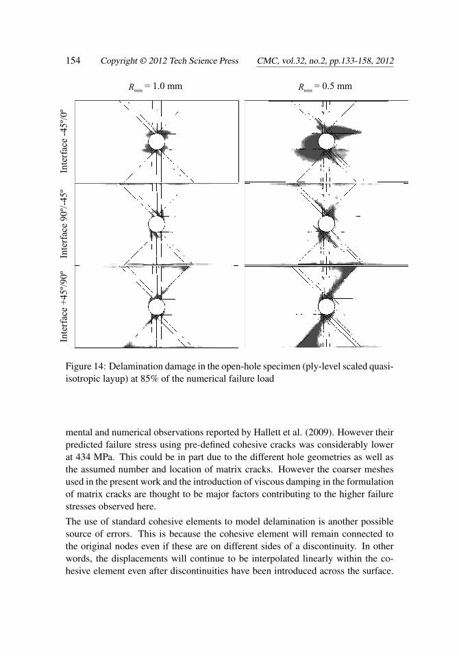
The delamination and transverse cracking behaviour for both values of Rmin wassimilar, with the case Rmin= 0.5 showing more damage for similar levels of ap-plied stress. This is illustrated in Figure 14 where delamination damage and matrixcracking are compared for the same applied load (which corresponds to 85% of thefailure load for Rmin= 1.0 mm).
Delaminations and matrix cracks initiated near the edge of the hole at relatively lowloads. Upon further loading, interface damage was observed also near the outeredges of the specimen especially along the +45o/90o ply interface. Interactions be-tween matrix cracks and delaminations are evident throughout the damage process.Matrix cracks extending along the full width were first observed in the surface plies(+45o). This promoted the ‘joining-up’ of the delaminations propagating from theopen-hole and the specimen edge along the +45o/90o ply interface, which was thenfollowed by the catastrophic failure of the specimen.
Good qualitative agreement was observed between these results and the experi-
Figure 14: Delamination damage in the open-hole specimen (ply-level scaled quasi-isotropic layup) at 85% of the numerical failure load
mental and numerical observations reported by Hallett et al. (2009). However theirpredicted failure stress using pre-defined cohesive cracks was considerably lowerat 434 MPa. This could be in part due to the different hole geometries as well asthe assumed number and location of matrix cracks. However the coarser meshesused in the present work and the introduction of viscous damping in the formulationof matrix cracks are thought to be major factors contributing to the higher failurestresses observed here.
The use of standard cohesive elements to model delamination is another possiblesource of errors. This is because the cohesive element will remain connected tothe original nodes even if these are on different sides of a discontinuity. In otherwords, the displacements will continue to be interpolated linearly within the co-hesive element even after discontinuities have been introduced across the surface.
Modelling Mesh Independent Transverse Cracks 155
However, because each cohesive element usually covers a small surface area, theseeffects will be small and will also be minimised with further mesh refinement. Onesolution to this problem would be to evaluate the cohesive law directly at nodesinstead of using interpolation via cohesive elements, as discussed in van der Meeret al. (2012). Although such a ‘discrete’ cohesive element is not readily availablein Abaqus/Explicit, it could be implemented in the form of a user-defined nonlinear‘spring’ element as described by Jiang et al. (2007). This is left as a recommenda-tion for future work.
4 Conclusions
A method has been proposed for the introduction of mesh-independent transversecracks in finite element models analysed using explicit time-integration. The methodsupports the initiation and propagation of large numbers of solution-dependentcracks and uses a cohesive zone modelling approach to describe crack propaga-tion. Because the formulation is designed for the analysis of matrix cracks in uni-directional composite plies, several assumptions could be made which simplifiedthe formulation considerably. This enabled its implementation as a user-definedelement subroutine in the commercial software Abaqus/Explicit. The model wasverified via the analysis of open-hole tension tests with two different layups. Com-parisons were made with experimental observations and numerical results availablein the literature. Qualitative agreement was observed in terms of the nucleation andpropagation of transverse cracks, predicted delamination patterns and the interac-tions between damage mechanisms. However the predicted failure stresses wereconsiderably higher than those observed experimentally. Possible reasons include(i) the likely presence of defects in real specimens, (ii) the use of coarse meshesand (iii) the absence of thermal residual stresses in the analyses. The latter two areconsequences of the long run-times observed for each analysis when using a serialversion of the code. The parallelisation and optimisation of the code are the focusof ongoing work which aims at addressing these issues.
References
Alfano, G.; Criseld, M.A. (2001): Finite element interface models for the delam-ination analysis of laminated composites: Mechanical and computational issues.Int. J. Numer. Meth. Engng., vol. 50, pp. 1701-1736.
Armero, F.; Linder, C. (2009): Numerical simulation of dynamic fracture usingfinite elements with embedded discontinuities. Int. J. Fract., vol. 160, pp. 119-141.
Belytschko, T.; Black, T. (1999): Elastic crack growth in finite elements withminimal remeshing; Int. J. Numer. Meth. Engng., vol. 45, iss. 5, pp. 601-620.
Camanho, P.P.; Dávila, C.G.; de Moura, M.F. (2003): Numerical simulation ofmixed-mode progressive delamination in composite materials. J. Compos. Mater.,vol. 37, pp. 1415-1438.
Dávila, C.G.; Camanho, P.P.; Rose, C.A. (2005): Failure criteria for FRP lami-nates; J. Compos. Mater., vol. 39, iss. 4, pp. 323–345.
Green, B.G.; Wisnom, M.R.; Hallett S.R. (2007): An experimental investigationinto the tensile strength scaling of notched composites. Compos. Part A-Appl. S.,vol. 38, iss. 3, pp. 867-878.
Hallett, S.R.; Jiang, W.G.; Khan, B.; Wisnom, M.R. (2008): Modelling the in-teraction between matrix cracks and delamination damage in scaled quasi-isotropicspecimens; Compos. Sci. Tech., vol. 68, iss. 1, pp. 80-89.
Hallett, S.R.; Green, B.G.; Jiang, W.G.; Wisnom, M.R. (2009): An experimen-tal and numerical investigation into the damage mechanisms in notched compos-ites; Compos. Part A-Appl. S., vol. 40, iss. 5, pp. 613-624.
Hansbo, A.; Hansbo, P. (2004): A finite element method for the simulation ofstrong and weak discontinuities in solid mechanics; Comput. Method. Appl. M.,vol. 193, pp. 3523-3540.
Harper, P.W.; Hallett, S.R. (2008): Cohesive zone length in numerical simulationsof composite delamination. Eng. Fract. Mech., vol. 75, iss. 16, pp. 4774-4792.
Iarve, E.V. (2003): Mesh independent modelling of cracks by using higher ordershape functions; Int. J. Numer. Meth. Engng., vol. 56, iss. 6, pp. 869–882.
Jiang, W.G.; Hallett, S.R.; Green, B.G.; Wisnom, M.R. (2007): A concise inter-face constitutive law for analysis of delamination and splitting in composite mate-rials and its application to scaled notched tensile specimens. Int. J. Numer. Meth.Engng., vol. 69, iss. 9, pp. 1982-1995.
Kawashita, L.F.; Hallett, S.R. (2012): A crack tip tracking algorithm for cohe-sive interface element analysis of fatigue delamination propagation in compositematerials. Int. J. Solids Struct., in press, DOI: 10.1016/j.ijsolstr.2012.03.034
Li, X; Hallett, S.R.; Wisnom, M.R. (2009): Numerical simulation of damagepropagation in overheight compact tension tests. 17th International Conference onComposite Materials (ICCM 17), Edinburgh, UK.
van der Meer, F.P.; Sluys, L.J. (2009): A phantom node formulation with mixedmode cohesive law for splitting in laminates. Int. J. Fracture, vol. 158, iss. 2, pp.107-124.
van der Meer, F.P.; Sluys, L.J.; Hallett, S.R.; Wisnom, M.R. (2012): Computa-tional modeling of complex failure mechanisms in laminates; J. Compos. Mater.;
Modelling Mesh Independent Transverse Cracks 157
vol. 46, iss. 5, pp. 603-623.
Melenk, J.M.; Babuska, I. (1996): The partition of unity finite element method:Basic theory and applications; Comput. Method. Appl. M., vol. 139, iss. 1-4, pp.289-314.
Menouillard, T.; Réthoré, J.; Combescure, A.; Bung, H. (2006) Efficient ex-plicit time stepping for the eXtended Finite Element Method (X-FEM). Int. J.Numer. Meth. Engng., vol. 68, pp. 911-939.
Möes, N.; Belytschko, T. (2002): Extended finite element method for cohesivecrack growth; Eng. Fract. Mech., vol. 69, iss. 7, pp. 813-833.
Nistor, I.; Pantale, O.; Caperaa, S. (2008): Numerical implementation of theeXtended Finite Element Method for dynamic crack analysis; Adv. Eng. Softw.,vol. 39, iss. 7, pp. 573-587.
Oguntoye, M.O.; Hallett, S.R. (2011): A Benchmark Test for XFEM in Com-posites. Dassault Systèmes UK Regional Users Meeting 2011, 18th-20th October2011, South Gloucestershire, UK.
Pinho, S.T.; Iannucci, L.; Robinson, P. (2006): Formulation and implementationof decohesion elements in an explicit finite element code. Compos. Part A-Appl.S., vol. 37, iss. 5, pp. 778-89.
Petrossian, Z.; Wisnom, M.R. (1998): Prediction of delamination initiation andgrowth from discontinuous plies using interface elements. Compos. Part A-Appl.S., vol. 29, pp. 503-515.
Puck, A.; Schurmann, H. (2002): Failure analysis of FRP laminates by meansof physically based phenomenological models; Compos. Sci. Tech., vol. 62, iss.12-13, pp. 1633-1662.
Remmers, J.J.C.; de Borst, R.; Needleman, A. (2003): A cohesive segmentsmethod for the simulation of crack growth; Comput. Mech., vol. 31, iss. 1-2, pp.69-77.
Remmers, J.J.C.; de Borst, R.; Needleman, A. (2008): The simulation of dy-namic crack propagation using the cohesive segments method; J. Mech. Phys.Solids, vol. 56, iss. 1, pp. 70-92.
Rybricki, E.F.; Kanninen, M.F. (1977): A finite element calculation of stressintensity factors by a modified crack closure integral; Eng. Fract. Mech., 9, pp.931-938.
Song, J.H.; Areias, P.M.A.; Belytschko, T. (2006): A method for dynamic crackand shear band propagation with phantom nodes; Int. J. Numer. Meth. Engng.; vol.67, iss. 6, pp. 868-893.
Song, J.H.; Wang, H.W.; Belytschko, T. (2008): A comparative study on finite
element methods for dynamic fracture. Comput. Mech., vol. 42, iss. 2, pp. 239-250.
Turon, A.; Dávila, C.G.; Camanho, P.P.; Costa, J. (2007): An engineering so-lution for mesh size effects in the simulation of delamination using cohesive zonemodels. Eng. Fract. Mech., vol. 74, iss. 10, pp. 1665-1682.
Wells, G.N.; Sluys, L.J. (2001): A new method for modelling cohesive cracksusing finite elements; Int. J. Numer. Meth. Engng., vol. 50, iss. 12, pp. 2667-2682.
Yang, Q.D.; Cox, B. (2005): Cohesive models for damage evolution in laminatedcomposites; Int. J. Fracture, vol. 133, iss. 2, pp. 107-137.


![UNIVERSITY OF THE BASQUE COUNTRY DETERMINATION OF TRANSVERSE COMPRESSIVE STRENGTH OF LONG FIBER COMPOSITES BY THREE-POINT BENDING OF [90m/0n] LAMINATED.](https://static.documents.pub/doc/80x56/56649d2e5503460f94a05143/university-of-the-basque-country-determination-of-transverse-compressive-strength.jpg)


![· Figure Il. Transverse crack-related defect in rebar [2]. Causes and solutions. Transverse cracks can form in the mould or during strengthening.](https://static.documents.pub/doc/80x56/5afeeaed7f8b9a256b8dbcde/il-transverse-crack-related-defect-in-rebar-2-causes-and-solutions-transverse.jpg)