International Conference Nuclear Energy for New Europe 2005 Bled, Slovenia, September 5-8, 2005 092.1 Modelling of Catalytic Recombiners: Comparison of REKO-DIREKT Calculations with REKO-3 Experiments E.-A. Reinecke, J. Boehm, P. Drinovac, S. Struth Institute for Safety Research and Reactor Technology (ISR) Forschungszentrum Juelich GmbH, D-52425 Juelich, Germany [email protected], [email protected]I.M. Tragsdorf Institute for Reactor Safety and Reactor Technology (LRST) RWTH Aachen University, D-52064 Aachen, Germany [email protected]ABSTRACT Numerous containments of European light water reactors (LWR) are equipped with passive autocatalytic recombiners (PAR). PARs make use of the fact that hydrogen and oxygen react exothermally on catalytic surfaces generating steam and heat even below conventional concentration limits and ignition temperatures. These devices are designed for the removal of hydrogen generated during a severe accident in order to limit the impact of a possible hydrogen combustion. Alongside many experimental programmes performed at different institutions in the past which demonstrated the technical feasibility of this approach, investigations also revealed that there is still research needed in order to optimise and to enhance existing systems. The knowledge of the processes inside recombiners is still limited. The numerical code REKO-DIREKT has been developed in order to analyse the processes inside a PAR. The code calculates the local catalyst and gas temperatures and the concentration regression along the catalyst plates dependent on the inlet hydrogen concentration, the inlet gas temperature, and the flow rate. Numerous experiments have been performed in the REKO-3 facility taking into account different hydrogen concentrations, different flow rates, the presence of steam, the lack of oxygen, and different arrangements of the catalyst elements. The experimental results are used for the validation of the code providing also data specific for sub-models, e.g. the heat radiation model. The first basic calculations fit well with the experimental results indicating a proper understanding of the fundamental processes. The paper presents model calculations performed and the comparison with experimental results. 1 INTRODUCTION Following many years of research and discussion about suitable hydrogen mitigation methods for nuclear installations after the TMI accident in 1979, today numerous containments of European light water reactors (LWR) are equipped with passive autocatalytic recombiners (PAR). These devices are designed for the removal of hydrogen generated during
Transcript
International ConferenceNuclear Energy for New Europe 2005
Bled, Slovenia, September 5-8, 2005
092.1
Modelling of Catalytic Recombiners: Comparison of REKO-DIREKT Calculations with REKO-3 Experiments
E.-A. Reinecke, J. Boehm, P. Drinovac, S. Struth Institute for Safety Research and Reactor Technology (ISR)
Numerous containments of European light water reactors (LWR) are equipped with passive autocatalytic recombiners (PAR). PARs make use of the fact that hydrogen and oxygen react exothermally on catalytic surfaces generating steam and heat even below conventional concentration limits and ignition temperatures. These devices are designed for the removal of hydrogen generated during a severe accident in order to limit the impact of a possible hydrogen combustion. Alongside many experimental programmes performed at different institutions in the past which demonstrated the technical feasibility of this approach, investigations also revealed that there is still research needed in order to optimise and to enhance existing systems. The knowledge of the processes inside recombiners is still limited.
The numerical code REKO-DIREKT has been developed in order to analyse the processes inside a PAR. The code calculates the local catalyst and gas temperatures and the concentration regression along the catalyst plates dependent on the inlet hydrogen concentration, the inlet gas temperature, and the flow rate. Numerous experiments have been performed in the REKO-3 facility taking into account different hydrogen concentrations, different flow rates, the presence of steam, the lack of oxygen, and different arrangements of the catalyst elements. The experimental results are used for the validation of the code providing also data specific for sub-models, e.g. the heat radiation model. The first basic calculations fit well with the experimental results indicating a proper understanding of the fundamental processes. The paper presents model calculations performed and the comparison with experimental results.
1 INTRODUCTION
Following many years of research and discussion about suitable hydrogen mitigation methods for nuclear installations after the TMI accident in 1979, today numerous containments of European light water reactors (LWR) are equipped with passive autocatalytic recombiners (PAR). These devices are designed for the removal of hydrogen generated during
092.2
a severe accident in order to avoid serious damage caused by a possible detonation of large hydrogen/air mixtures. Based on the fact that hydrogen and oxygen react exothermally on catalytic surfaces even below conventional concentration limits and ignition temperatures, PARs are considered as safety directed devices reducing the risk of a detonation inside the containment [1]. However, limited conversion capacities that may not be sufficient at high hydrogen release rates or overheating of the catalyst elements caused by strong reaction heat generation that may lead to unintended ignition of the gaseous mixture are known important issues for improving today’s systems. However, the present lack of detailed knowledge with regard to the processes inside PARs make any optimisation effort difficult.
Consequently, the ISR activities in the field of hydrogen control for LWR aim at achieving a profound understanding of the processes inside recombiners. Since 1996, experiments at ISR are performed to achieve a profound understanding of the processes inside a recombiner, such as reaction kinetics or heat and mass transfer. The REKO-3 test facility was designed to investigate the behaviour of a small recombiner section under well defined steady-state conditions. Catalyst temperatures and hydrogen concentration depletion along the catalyst sheets are the main measurements to yield information about the conversion process. These experiments provide an excellent database for the validation of numerical recombiner codes.
For the analysis of the processes inside a PAR such as reaction kinetics or heat and mass transfer the numerical code REKO-DIREKT is being developed. The code calculates the local catalyst temperature and the concentration regression along the catalyst plates. The accompanying experiments at the REKO facilities support the modelling process by building a database for the validation of the numerical recombiner model. Innovative PAR designs can be developed based on the knowledge obtained from these investigations.
2 REKO-3 EXPERIMENTAL PROGRAMME
The experiments at the REKO-3 test facility (Fig. 1) serve basically to clarify the interactions of reaction kinetics, heat and mass transfer, and the flow conditions inside the recombiner. The experimental set-up allows the investigation of catalyst samples inside a
Proceedings of the International Conference “Nuclear Energy for New Europe 2005”
092.3
vertical flow channel under well defined conditions comprising gas mixture, flow rate and inlet temperature. The catalyst sheets (stainless steel coated with washcoat/platinum catalyst material) are arranged in parallel forming vertical rectangular flow channels. Such a set-up represents a box-type recombiner section of Framatome-ANP design. This design is the most common implemented in European LWRs [2].
2.1 Experimental set-up
Inside of the configuration the distribution of the catalyst temperatures and the gas compositions in the vertical flow direction are measured (Fig. 2). In general, the experiments have been performed for three different flow rates (0.25 m/s, 0.5 m/s, and 0.8 m/s), for three different inlet gas temperatures (25°C, 70°C, and 110°C), and for hydrogen concentrations between 0.5 vol.% and 4.0 vol.%.
143 x 143 mm²(1,5 mm sheets)
INLET• flow rate• gas temperature• gas composition
OUTLET• gas temperature• gas composition CATALYST PLATE
• catalyst temperatureat 10 different locations
REACTION ZONE• gas compositionat 14 different locations
Figure 2: REKO-3 measuring points
For measuring the distribution of the catalyst temperatures the catalyst sheets are
equipped with thermocouples. In order not to disturb neither the gas flow nor the catalyst
Substrate: sheets, stainless steel,143 x 143 x 1.5 mm
Catalyst: platinum on washcoatCoating: 5.0 g Pt/m²Company: Engelhard
Drill technique: spark erosionDrill diameter: 0.6 mmTC diameter: 0.5 mm
Figure 3: Recombiner section with inserted thermocouples
Proceedings of the International Conference “Nuclear Energy for New Europe 2005”
092.4
coating drillings were manufactured by means of spark erosion enabling thin thermocouples to be inserted at different locations inside the samples (Fig. 3).
A new feature implemented in the test facility is the measurement of the gas concentrations in the flow channel along the catalyst sheets. The probe head is introduced at different positions allowing measurement of the hydrogen depletion in flow direction. A total of 14 sample points has been implemented. The measurement gas is conducted from the sample point through a cooler and condensate trap. Hydrogen and oxygen concentrations are measured in line by separate systems (Fig. 4).
Bypass
Pump TemperatureGas analysis
Probe head Cooler Molecular sieve
Choke
System control
Figure 4: Flow sheet of the REKO-3 gas analysis section
2.2 Experimental results
Some exemplary measurement results are given in Fig. 5. These steady-state distributions of the hydrogen concentration (left side) and the catalyst temperature (right side) were obtained at 2 vol.% and 4 vol.% inlet hydrogen concentration, the inlet gas temperature
x/
mm
0
20
40
60
80
100
120
140
0 200 400 600
T / °C
yH2,E/ Vol.-% 2,0 4,0
T' = 25 °Cv' = 0.80 m/s
x/
mm
0
20
40
60
80
100
120
140
0 2 4 6yH2 / vol.%
yH2,E/ Vol.-%2,0 4,0
Figure 5: Steady-state hydrogen depletion (left side) and catalyst temperatures
(right side) along the catalyst sheets for two different hydrogen inlet concentrations at 25°C inlet temperature and a flow rate of 0.8 m/s
Proceedings of the International Conference “Nuclear Energy for New Europe 2005”
092.5
of 25°C and a flow rate of 0.8 m/s. The symbols represent measuring values while the lines are added for the sake of clarity. The measured values are plotted on the horizontal axis in order to illustrate the vertical arrangement of the catalyst plates. Experimental results obtained have been described in more detail in [3] (only catalyst temperatures).
The main part of the conversion reaction takes place in the very first area of the catalyst surface. This is reflected by the first sharp concentration drop as well as by the temperature profile where the maximum temperature is located close to the leading edge of the catalyst sheet (x = 0 mm). However, the drop is not as pronounced as it had been conducted from former model calculations e.g. in [4]. The temperature rise closer to the trailing edge is to some extent caused by heat conduction and convective heat transport. Maximum temperatures reach the conventional ignition limit of about 560°C already at a hydrogen concentration of 4 vol.% hence representing the risk of an unintended ignition.
In addition to these experiments representing the reference case using catalyst sheets fully coated on both sides, the REKO-3 test facility is designed to allow the investigation of new catalyst arrangements. Experiments already conducted include
• sheets only partially coated (the first 27 mm at the leading edge were left uncoated),
• sheets coated with stripes of catalyst material, • sheets coated on both sides with alternating stripes of catalyst material, and • additional uncoated sheets arranged between the catalyst sheets.
3 NUMERICAL MODEL REKO-DIREKT
As described above, the REKO-3 test facility represents a section of four catalyst plates of a recombiner. Again a section from the test facility set-up, the numerical code REKO-DIREKT represents the middle flow channel and both adjacent catalyst plates (Fig. 6). The particular plate centres in vertical direction are defined as adiabatic boundaries as the conditions in the neighbouring flow channels are identical and no significant temperature differences are to be expected.
outlet
catalystsheetsinlet
Box-type recombiner REKO-3 REKO-DIREKT Figure 6: Representation of the recombiner in the experiment
and in the numerical model
Proceedings of the International Conference “Nuclear Energy for New Europe 2005”
092.6
3.1 Model description
The model in Cartesian coordinates considers the state equations in flow direction (x-direction) as well as between both adjacent plates (y-direction). Changes of the state variables along the plate across the flow direction are considered as negligible and hence not calculated. Fig. 7 shows a section of the model at the flow inlet superposed with a 2-dimensional numerical grid. In the flow channel only one mesh in y-direction is applied in order to permit the use of empirical heat and mass transfer laws.
yn
x i
convectionconductionenthalpyradiation
Figure 7: Heat transport in the 2-dimensional numerical model
The heat flow between the meshes is calculated as indicated in Fig. 7. Inside the plates
heat is transported by heat conduction. Inside the flow channel the enthalpy flow, heat conduction inside the gas, heat transfer at the plate surface, and radiation between the walls are considered. Heat radiation is modelled as heat source/sink obtained from the net radiation exchange rate which enables considering the heat exchange with all surfaces including losses via the openings.
Heat sources resulting from the exothermal reaction are calculated in each flow mesh on the left and right boundary provided catalytic activity has been defined for the respective surface. Under the given conditions, the catalytic recombination is diffusion controlled [5]. Consequently, the modelling of the reaction kinetics is based on a mass transfer approach instead of the usual Arrhenius-type approach for chemical surface reactions.
The local heat source is calculated according to RQ&
RR HzxrQ ∆⋅⋅⋅= && (1) where r& is the reaction rate, zx ⋅ the surface area and RH∆ the reaction enthalpy. The
reaction rate is modelled with a mass transfer approach
2HCr ∆β ⋅=& . (2)
Proceedings of the International Conference “Nuclear Energy for New Europe 2005”
092.7
In this equation 2HC∆ represents the hydrogen concentration difference between the bulk flow and the plate surface. As the hydrogen concentration on the surface is assumed to be zero (complete hydrogen conversion) the value of the hydrogen concentration in the bulk flow may be used leading to
TRpyCC 222 HBulk,HH⋅
⋅==∆ (3)
with the molar hydrogen concentration , the pressure p, the gas constant R, and the
gas temperature T. The mass transfer coefficient 2Hy
β in Eq. (2) is calculated from the Sherwood number Sh as follows:
h
m,H
dDSh 2⋅=β (4)
where is the diffusion coefficient of hydrogen in the gaseous mixture and is
the hydraulic diameter. The Sherwood number is obtained from empirical correlations as a function of the Reynolds number Re and the Schmidt number Sc.
m,H 2D hd
The resulting steady-state equation system is transformed into a band matrix and then solved by means of a direct closed algorithm. As this approach doesn’t require spatial iterations the numerical solutions are very stable and exact.
3.2 Comparison with experiments
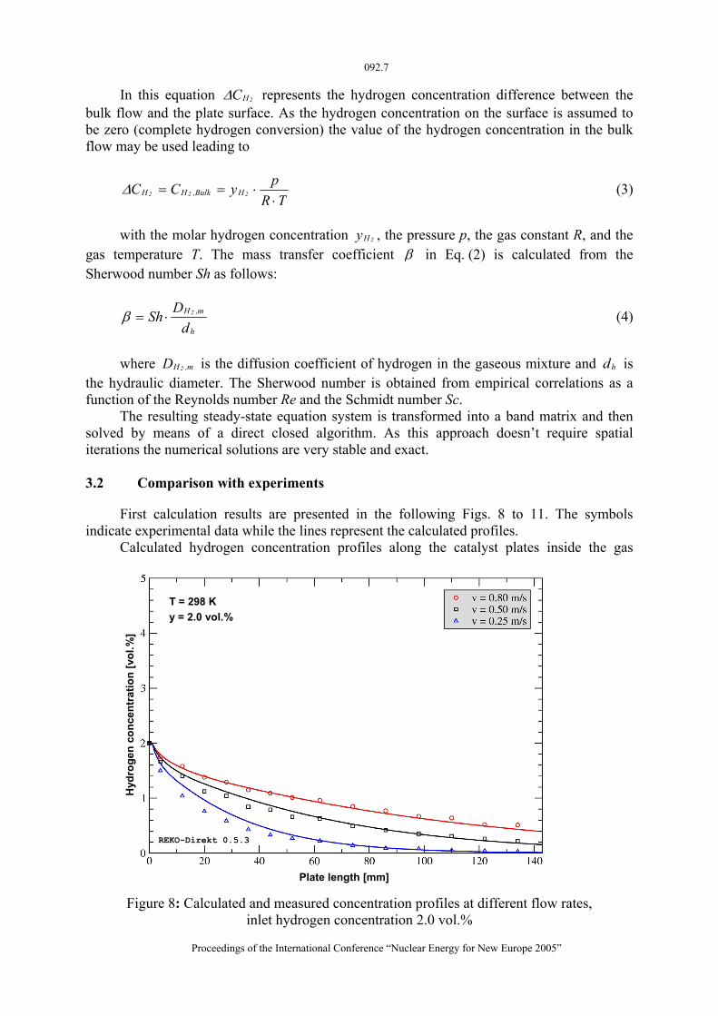
First calculation results are presented in the following Figs. 8 to 11. The symbols indicate experimental data while the lines represent the calculated profiles.
Calculated hydrogen concentration profiles along the catalyst plates inside the gas
Hyd
roge
n co
ncen
trat
ion
[vol
.%]
Plate length [mm]
T = 298 Ky = 2.0 vol.%
REKO-Direkt 0.5.3
Figure 8: Calculated and measured concentration profiles at different flow rates,
inlet hydrogen concentration 2.0 vol.%
Proceedings of the International Conference “Nuclear Energy for New Europe 2005”
092.8
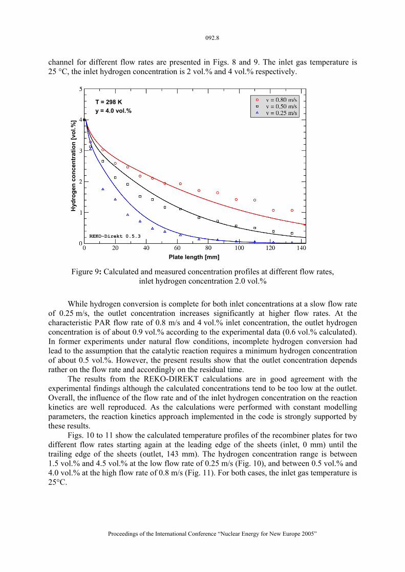
channel for different flow rates are presented in Figs. 8 and 9. The inlet gas temperature is 25 °C, the inlet hydrogen concentration is 2 vol.% and 4 vol.% respectively.
H
ydro
gen
conc
entr
atio
n [v
ol.%
]
Plate length [mm]
T = 298 Ky = 4.0 vol.%
REKO-Direkt 0.5.3
Figure 9: Calculated and measured concentration profiles at different flow rates,
inlet hydrogen concentration 2.0 vol.%
While hydrogen conversion is complete for both inlet concentrations at a slow flow rate
of 0.25 m/s, the outlet concentration increases significantly at higher flow rates. At the characteristic PAR flow rate of 0.8 m/s and 4 vol.% inlet concentration, the outlet hydrogen concentration is of about 0.9 vol.% according to the experimental data (0.6 vol.% calculated). In former experiments under natural flow conditions, incomplete hydrogen conversion had lead to the assumption that the catalytic reaction requires a minimum hydrogen concentration of about 0.5 vol.%. However, the present results show that the outlet concentration depends rather on the flow rate and accordingly on the residual time.
The results from the REKO-DIREKT calculations are in good agreement with the experimental findings although the calculated concentrations tend to be too low at the outlet. Overall, the influence of the flow rate and of the inlet hydrogen concentration on the reaction kinetics are well reproduced. As the calculations were performed with constant modelling parameters, the reaction kinetics approach implemented in the code is strongly supported by these results.
Figs. 10 to 11 show the calculated temperature profiles of the recombiner plates for two different flow rates starting again at the leading edge of the sheets (inlet, 0 mm) until the trailing edge of the sheets (outlet, 143 mm). The hydrogen concentration range is between 1.5 vol.% and 4.5 vol.% at the low flow rate of 0.25 m/s (Fig. 10), and between 0.5 vol.% and 4.0 vol.% at the high flow rate of 0.8 m/s (Fig. 11). For both cases, the inlet gas temperature is 25°C.
Proceedings of the International Conference “Nuclear Energy for New Europe 2005”
092.9
T = 298 Kv = 0.25 m/s
Plate length [mm]
Cat
alys
t tem
pera
ture
[K]
REKO-Direkt 0.5.3
Figure 10: Calculated and measured temperature profiles at different inlet
hydrogen concentrations, flow rate 0.25 m/s
Again, the calculated profiles agree well with the experimental data. The minor
deviations at very low hydrogen concentrations (0.5 vol.%) may indicate that the modelling approach is not suitable at lower temperatures when decelerated surface processes may influence the overall process.
T = 298 Kv = 0.80 m/s
Plate length [mm]
Cat
alys
t tem
pera
ture
[K]
REKO-Direkt 0.5.3
Figure 11: Calculated and measured temperature profiles at different inlet
hydrogen concentrations, flow rate 0.8 m/s
Proceedings of the International Conference “Nuclear Energy for New Europe 2005”
092.10
4 CONCLUSIONS
The numerical code REKO-DIREKT has been developed at ISR in order to analyse the processes inside a PAR. The depletion of hydrogen along the catalyst sheets and the catalyst heating has been calculated for different inlet conditions. The calculated hydrogen concentration and catalyst temperature curves along the catalyst sheets have been compared with experimental data obtained from REKO-3 experiments. Numerical and experimental data are in good agreement. The results indicate that the code is capable to realistically represent the essential processes within a recombiner. Further code development steps are foreseen including:
• code validation with additional experimental set-ups, • including natural convection models, • extension to multiple channels, • upgrading to transient calculations, and • extension to further catalyst geometries.
ACKNOWLEDGEMENTS
The REKO-DIREKT development as well as the REKO-3 experiments are performed as part of the CONTAINMENT activity within the Severe Accident Research Network (SARNET) in the 6th European Framework Programme. Experimental data have been made available to SARNET partners for code validation.
REFERENCES
[1] W. Zhong (Ed.), Mitigation of Hydrogen Hazards in Water Cooled Power Reactors, IAEA-TECDOC-1196, IAEA, Vienna, ISSN 1011-4289, 2001.
[2] E. Bachellerie, et al., State-of-the-art Report on Passive Autocatalytic Recombiners - Handbook Guide for Implementing Catalytic Recombiners, Technicatome Company Report, Technical Note TA-185706 Ind. A., 2002.
[3] E.-A. Reinecke, I.M. Tragsdorf, K. Gierling, Studies on Innovative Hydrogen Recombiners as Safety Devices in the Containments of Light Water Reactors, Nuclear Engineering and Design, vol. 230, 2004, pp. 49-59.
[4] M. Heitsch, Fluid Dynamic Analysis of a Catalytic Recombiner to Remove Hydrogen, Nuclear Engineering and Design, vol. 201, 2000, pp. 1-10.
[5] E.-A. Reinecke, Reaktionskinetische Untersuchungen zur Auslegung von katalytischen Wasserstoffrekombinatoren, PhD Thesis, RWTH Aachen University, Aachen, Germany, 1999.
Proceedings of the International Conference “Nuclear Energy for New Europe 2005”