4600 Series Operating Instructions Models 4623 and 4628 Conductivity Transmitters To Meet United States Pharmacopœia (USP 23) Regulations 4600 µ S/cm 25° C 0 .50 A1 A2 4600 0 . 50 A1 A2 µ S/cm 25° C
Transcript
4600 Series Operating Instructions
Models 4623 and 4628Conductivity TransmittersTo Meet United StatesPharmacopœia (USP 23)Regulations
4600
µS/cm 25°C0 .50
A1
A2
4600
0 . 50
A1
A2
µS/cm 25°C
0255
ABB AUTOMATION
The Company
ABB Automation is an established world force in the design and manufacture ofinstrumentation for industrial process control, flow measurement, gas and liquid analysis andenvironmental applications.
As a part of ABB, a world leader in process automation technology, we offer customersapplication expertise, service and support worldwide.
We are committed to teamwork, high quality manufacturing, advanced technology andunrivalled service and support.
The quality, accuracy and performance of the Company’s products result from over 100 yearsexperience, combined with a continuous program of innovative design and development toincorporate the latest technology.
The NAMAS Calibration Laboratory No. 0255 is just one of the ten flow calibration plantsoperated by the Company, and is indicative of ABB Automation’s dedication to qualityand accuracy.
Use of Instructions
Warning.An instruction that draws attention to the risk of injury ordeath.
Caution.An instruction that draws attention to the risk of damage tothe product, process or surroundings.
Note.Clarification of an instruction or additional information.
Information.Further reference for more detailed information ortechnical details.
Although Warning hazards are related to personal injury, and Caution hazards are associated with equipment or property damage,it must be understood that operation of damaged equipment could, under certain operational conditions, result in degradedprocess system performance leading to personal injury or death. Therefore, comply fully with all Warning and Caution notices.
Information in this manual is intended only to assist our customers in the efficient operation of our equipment. Use of this manualfor any other purpose is specifically prohibited and its contents are not to be reproduced in full or part without prior approval ofMarketing Communications Department, ABB Automation.
Health and SafetyTo ensure that our products are safe and without risk to health, the following points must be noted:
1. The relevant sections of these instructions must be read carefully before proceeding.
2. Warning labels on containers and packages must be observed.
3. Installation, operation, maintenance and servicing must only be carried out by suitably trained personnel and in accordance with theinformation given.
4. Normal safety precautions must be taken to avoid the possibility of an accident occurring when operating in conditions of high pressureand/or temperature.
5. Chemicals must be stored away from heat, protected from temperature extremes and powders kept dry. Normal safe handling proceduresmust be used.
6. When disposing of chemicals ensure that no two chemicals are mixed.
Safety advice concerning the use of the equipment described in this manual or any relevant hazard data sheets (where applicable) may beobtained from the Company address on the back cover, together with servicing and spares information.
BS EN ISO 9001
St Neots, U.K. – Cert. No. Q5907Stonehouse, U.K. – Cert. No. FM 21106
7 PROGRAMMING........................................................ 167.1 Access to Secure Parameters ........................ 177.2 Language Page ............................................... 177.3 Set Up Parameters Page ................................ 177.4 Set Up Alarms Page ........................................ 187.5 Set Up Retransmission Page .......................... 20
APPENDICES ..................................................................... 27A1 Automatic Temperature Compensation .......... 27
2
The 4623 and 4628 conductivity transmitters and associatedmeasuring cells have been designed to meet United StatesPharmacopœia (USP 23) requirements for continuousmonitoring and control of the conductivity of demineralisedwater, and de-ionised water.
The 4623 model is a wall-mounted instrument and the 4628model a panel-mounted, DIN sized instrument. Bothinstruments have a single programmable conductivity inputchannel and a single temperature input channel. Whenmaking temperature compensated measurements the sampletemperature is sensed by a Pt100 resistance thermometermounted in the measuring cell or, alternatively, using aseparate temperature sensor.
Instrument operation and programming is via four tactilemembrane keys located on the front panel. Programmedfunctions are protected from unauthorised alteration by a five-digit security code.
2.1 Checking the Code Number
2.1.1 Wall-/Pipe-mounted Instruments – Fig. 2.1
(Wall-Mounted Model)
4623/500
2.1.2 Panel-mounted Instruments – Fig. 2.2
Slide instrumentout of case
(Panel-Mounted Model)
4628/500
Undo captivescrew
Remove plug(if fitted)
12
3
Fig. 1.1 System Schematic
4600
µS/cm 25°C0.50
A1
A2
4600
0.50
A1
A2
µS/cm 25°C
1 INTRODUCTION 2 PREPARATION
Fig. 2.1 Checking the Code Number (Model 4623)
Fig. 2.2 Checking the Code Number (Model 4628)
3
2.1.3 Conductivity Cells – Fig. 2.3
Model 2278/305
Basic Type No. Version Constant (K) ProcessConnection
Type
TemperatureCompensation
Code Characters1, 2 3, 4, 5 6 7 8
22 Electrolyticconductivitymeasuringcells
0 2in. Tri-cloverHygienic fitting
0 None
5 Pt100resistancethermometer
78/ Stainless steel 3 0.05
2 PREPARATION
Fig. 2.3 Checking the Conductivity Cell Code Number
4
3.1 Siting Requirements
3.1.1 Instruments – Fig. 3.1
Caution.
• Mount in a location free from excessive vibration.
• Mount away from harmful vapours and/or dripping fluids.
Information. It is preferable to mount theinstrument at eye level, allowing an unrestricted view ofthe front panel displays and controls
3.1.2 Conductivity Cells – Fig. 3.2
Caution. Ensure that the integral cable (whereapplicable) does not hang against hot or abrasive objectswhen the plug is connected to the bulkhead socket.
Note. Allow sufficient clearance for easy removal ofcell for cleaning – see Section 3.4 for overall dimensionsof cells.
3.2.1 Wall-/Pipe-mounted Instruments – Figs. 3.3 and 3.4
Mark fixing centres(see Fig. 3.3)
Drill suitableholes
Fix instrument towall using
suitable fixing
1
2
3
Position ‘U’ bolts on pipe
Position plates over ‘U’ bolts
Secure transmitter to mounting plate
Secure plates
1
2
3
4
160 (6.3)
250(9.84)
69 (2.72)
Fixing Centres
Allowance forCable Bends200 (7.9)
68 (2.68)
214(8.43)
232(9.13)
Fix
ing
Cen
tres
42(1.65)
61 (23/8) O.D. Vertical or Horizontal Post
Dimensions inmm (in)
3 MECHANICAL INSTALLATION…
Fig. 3.3 Overall Dimensions
Fig. 3.4 Wall-/Pipe-mounting
A – Wall-mounting B – Pipe-mounting
6
…3.2 Mounting
3.2.2 Panel-mounted Instruments – Figs. 3.5 and 3.6
Dimensions in mm (in)
96 (3.78)
96(3.78)
191 (7.52)12 (0.47)
Panel Cut-out+0.8–092
(3.62 )+0.03–0
+0.8–092 (3.62 )+0.03
–0
Cut a hole in the panel (see Fig. 3.5 for dimensions).Instruments may be close stacked to DIN 43835.
Insert the instrumentinto the panel cut-out.
Refit the panel clamps to the case, ensuring that thepanel clamp anchors are located correctly in their slot.
Secure the instrument by tighteningthe panel clamp retaining screws.
Loosen the retaining screwon each panel clamp.
Remove the panel clamp andanchors from the instrument case.
1
2
3
4
5
6
3
…3 MECHANICAL INSTALLATION
Fig. 3.5 Overall Dimensions
Caution. The clamp must fit flat on theinstrument casing. If the clamp is bowed, the securingscrew is overtight and sealing problems may occur.
Fig. 3.6 Panel Mounting
7
3.3 Cleaning Conductivity CellsBefore installing a conductivity cell, clean the electrodes asfollows.
3.3.1 Stainless Steel Conductivity CellsUnscrew the outer electrode and thoroughly clean it with anylon-bristle brush (supplied) and a warm detergent solution.Clean the central electrode in a similar manner, taking care notto damage it. For more tenacious deposits a 2% hydrochloricacid solution may be used. Rinse thoroughly with distilledwater after cleaning. The electrodes should have a dull,frosted appearance which must not be removed by polishingor abrasive cleaning. Refit the outer electrode.
3.4 Installing the Conductivity Cells
Caution. After cleaning and installing aconductivity cell, ensure it remains filled with liquid and isnot allowed to dry out.
3.4.1 Bulkhead Socket – Fig. 3.7
3.4.2 Model 2278 Cell Dimensions – Fig. 3.8
Dimensions in mm
2 Fixing Holes5mm dia.
100Clearancefor removal
of plug
83
89
70
76
M20Conduit
Gland Entry
Dimensions in mm
22 dia
95
200
WeldedCollar
GasketTri-Clamp
63.550
3 MECHANICAL INSTALLATION
Note. Used with cell types 2278. Mount thesocket at a convenient location close to the cell.
Fig. 3.7 Bulkhead Socket
Fig. 3.8 Model 2278 Cell Dimensions
8
Warning. Before making any connections, ensure that the power supply, any high voltage-operated control circuitsand high common mode voltages are switched off.
4.1 Access to Terminals
4.1.1 Wall-/Pipe-mounted Instruments – Fig. 4.1
4.1.2 Panel-mounted Instruments – Fig. 4.2
Earth Studs
slidedown
Pull outslightly. . .
. . . andslide off
Removeprotectioncover
Slackencaptivescrew
3
4
2
1
2
Remove nuts andprotection cover
Removemains cover
Mains Cover
1
2
4 ELECTRICAL CONNECTIONS
Fig. 4.1 Access to Terminals – Wall-/Pipe-mounted Instruments
Fig. 4.2 Access to Terminals – Panel-mounted Instruments
9
NC C NO
ExternalD.C. Supply
+ –
Relay Contacts
Load
Diode
NC C NO
ExternalA.C. Supply
L N
Relay Contacts
CR
Load
4.2 Connections, General
Information.
• Earthing (grounding) – stud terminal(s) is (are) fitted to the transmitter case for bus-bar earth (ground) connection – seeFig. 4.1 or 4.5.
• Cable lengths – the integral cable may be extended using a suitable junction box but the total cable length must notexceed 164 ft. (50m) for cells with a constant of <0.05 (as is the case for cell model 2278/305).
• Cable routing – always route signal output/conductivity cell cable leads and mains-carrying/relay cables separately,ideally in earthed metal conduit. Employ twisted pair output leads or use screened cable with the screen connected to thecase earth stud.
Ensure that the cables enter the transmitter through the glands nearest the appropriate screw terminals and are short anddirect. Do not tuck excess cable into the terminal compartment.
• Cable glands & conduit fittings – ensure a moisture-tight fit when using cable glands, conduit fittings and blanking plugs/bungs (M20 holes). The M16 glands ready-fitted to wall-mounted instruments accept cable of between 4 and 7mmdiameter.
• Relays –the relay contacts are voltage-free and must be appropriately connected in series with the power supply and thealarm/control device which they are to actuate. Ensure that the contact rating is not exceeded. Refer also to Section 4.2.1(below) for relay contact protection details when the relays are to be used for switching loads.
• Retransmission output – Do not exceed the maximum load specification for the selected current retransmission range– see Section 10, SPECIFICATION.
The retransmission output is isolated therefore the –ve terminal must be connected to earth (ground) if connecting to theisolated input of another device.
4.2.1 Relay Contact Protection and Interference Suppression – Fig. 4.3If the relays are used to switch loads on and off, the relay contacts can become eroded due to arcing. Arcing also generates radiofrequency interference (RFI) which can result in instrument malfunctions and incorrect readings. To minimize the effects of RFI,arc suppression components are required; resistor/capacitor networks for a.c. applications or diodes for d.c. applications. Thesecomponents can be connected either across the load or directly across the relay contacts. On 4600 Series instruments, the RFIcomponents must be fitted to the relay terminal block along with the supply and load wires – see Fig 4.3.
For a.c. applications the value of the resistor/capacitor network depends on the load current and inductance that is switched.Initially, fit a 100R/0.022µF RC suppressor unit (part no. B9303) as shown in Fig. 4.3A. If the instrument malfunctions (locks up,display goes blank, resets etc.) the value of the RC network is too low for suppression and an alternative value must be used. Ifthe correct value cannot be obtained, contact the manufacturer of the switched device for details on the RC unit required.
For d.c. applications fit a diode as shown in Fig. 4.3B. For general applications use an IN5406 type ( 600V peak inverse voltageat 3A – part no. B7363).
Note. For reliable switching the minimum voltage must be greater than 12V and the minimum current greater than100mA.
Caution. Slacken terminal screws fully before making connections.
Channel 1 Channel 2 PowerSupply
Retransmission Relay 1Relay 2
Serial
Channel 1 Channel 2 PowerSupply
Retrans. Relay 1Relay 2
1 2 3 4 5 6 7 + – N L
Serial(If fitted)
1 2 3
4 5 6
1 2 3
4 5 6
1234
––––
Braid
WhiteBlack
Conductivity Cell Temperature Compensator
567
–––
BrownGreen/YellowBlue
123456
––––––
Rx+Rx–Tx+Tx–0V
+–
Retrans.Output
Relays
123456
––––––
NCCNONCCNO
Relay 1
Relay 2
Mains Supply
NL
––
NeutralLine
– Earth(Ground)
OutputRS422/RS485
Earth (Ground) Stud(on case) –see Fig. 4.1
Earth (Ground) Stud(on case) – see Fig. 4.1
NCCNO
Normally ClosedCommonNormally Open
===
2nd Retrans. output4 –ve5 +ve
Refer to Table 4.1 belowfor terminal descriptions
…4 ELECTRICAL CONNECTIONS
Warning. The power supply earth (ground) must be connected to ensure safety to personnel, reduction of theeffects of RFI interference and correct operation of the power supply interference filter.
Caution. The metal braid in the conductivity cell connecting cable must not be earthed (grounded), orallowed to touch earthed (grounded) components, and must be cut back to the insulation at the conductivity cell end.
Note.• Metal cells (isolated from earth [ground]), e.g. if mounted in plastic pipe or pocket – connect terminal 4 to earth
(ground).• Metal cells (earthed [grounded]) – ensure that the cell ground potential and that of the instrument's earth (ground)
Warning. The power supply earth (ground) must be connected to ensure safety to personnel, reduction of theeffects of RFI interference and correct operation of the power supply interference filter. Connect the earth (ground)lead directly to the case earth (ground) stud and not to the 'E' terminal.
Caution. The metal braid in the conductivity cell connecting cable must not be earthed (grounded), orallowed to touch earthed (grounded) components, and must be cut back to the insulation at the conductivity cell end.
Note.• Metal cells (isolated from earth [ground]), e.g. if mounted in plastic pipe or pocket – connect terminal 9 to earth
(ground).• Metal cells (earthed [grounded]) – ensure that the cell ground potential and that of the instrument's earth (ground)
stud are the same.
Fig. 4.5 Panel-mounted Instrument Connections
12
4.5 Selecting the Mains Voltage
4.5.1 Wall-/Pipe-mounted Instruments – Fig. 4.6
4.5.2 Panel-mounted Instruments – Fig. 4.7
Slide instrumentout of case
Undo captivescrew
Remove plug(if fitted)
12
3
Selectthe mainsvoltagerequired
115
115
115V
230V
115
4
230
Remove cover (see Fig. 4.1)
Slacken captive screwsand remove
protection covee
Remove frontpanel screws
Remove frontpanel
Select the mains voltagerequired
Remove capand screw
230
230V
115V
1
2
3
4
5
3
…4 ELECTRICAL CONNECTIONS
Fig. 4.6 Selecting the Mains Voltage – Wall-/Pipe-mounted Instruments.
Fig. 4.7 Selecting the Mains Voltage – Panel-mounted Instruments
Information. Use a small,flat-bladed screwdriver to removethe screw cap from the case.
13
4.6 Conductivity Cell and Bulkhead SocketConnections – Fig. 4.8
1
2
34
BlackBrown
Green/Yellow
WhiteBlue
0233/819Cable0233/811
Cable
4 ELECTRICAL CONNECTIONS
Information. Use only the recommended cables:J/0233/811 (cell electrodes)J/0233/819 (temperature compensator only)
Note. Socket viewed from inside.
Fig. 4.8 Conductivity Cell and Bulkhead SocketConnections
14
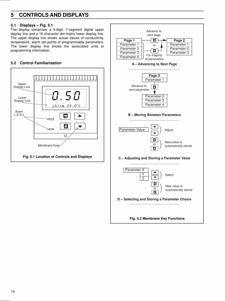
5.1 Displays – Fig. 5.1The display comprises a 5-digit, 7-segment digital upperdisplay line and a 16-character dot-matrix lower display line.The upper display line shows actual values of conductivity,temperature, alarm set points or programmable parameters.The lower display line shows the associated units orprogramming information.
5.2 Control Familiarisation A – Advancing to Next Page
Parameter 1Parameter 2Parameter 3Parameter 4
Page 1Parameter 1Parameter 2Parameter 3
Page 2
Advance tonext page
For majorityof parameters
or
B – Moving Between Parameters
C – Adjusting and Storing a Parameter Value
New value isautomatically stored
Parameter Value Adjust
D – Selecting and Storing a Parameter Choice
Parameter XYZ
Select
or
New value isautomatically storedor
Parameter 1
Parameter 2Parameter 3
Page X
Parameter 4
Advance tonext parameter
0 . 5 0µS/cm 25.0°C
AlarmL.E.D.s
UpperDisplay Line
LowerDisplay Line
Membrane Keys
5 CONTROLS AND DISPLAYS
Fig. 5.1 Location of Controls and Displays
Fig. 5.2 Membrane Key Functions
15
6.1 Instrument Start-upEnsure all electrical connections have been made correctly and switch on.
6.2 Operating PageThe Operating Page is a general use page in which parameters are viewed only and cannot be altered. To alter or program aparameter refer to the programming pages in Section 7.
Sample Conductivity and Temperature:The upper display line shows the conductivity of the sample in µS/cm.The lower display line shows the temperature of the sample in the units selected inSection 7.3, Set up Parameters Page.
These two keys are used to advance to all subsequent parameters and pages.
Adjusted Conductivity:The instrument software adjusts the measured conductivity of the sample to the value itwould be if the temperature of the sample was 25°C (77°F).The upper display line shows the adjusted conductivity value in µS/cm.
Alarm 1 Set Point:The set point value and relay/l.e.d. action are programmable – see Section 7.4, Set UpAlarms Page.
Alarm 2 Set Point:The set point value and relay/l.e.d. action are programmable – see Section 7.4, Set UpAlarms Page.Alarm 2 type set to Temp or Cond – Programmed Alarm Setpoint is displayed.Alarm 2 type set to USP – USP Alarm (including offset) is displayed.
Advance to Access to Secure Parameters on page 17.
µS/cm xx.x°C
0 . 5 0
Alarm 1 Setpoint
4 . 0 0
Alarm 2 Setpoint
1 . 0 0
Press to advanceto next parameter
Press to advanceto next page
or
µS/cm at 25.0°C
1 . 3 0
SECURITY CODE
0 0 0 0 0
6 OPERATION
16
1 .3
0µS/cm xx.x
°C
Alarm 2 Setpoint
1 .0
0Alarm 1 Setpoint
µS/cm at 25.0
°C
Op
erat
ing
Pag
eS
ectio
n 6.
2 , P
age
15S
et U
p A
larm
s P
age
Sec
tion
7.4,
Pag
e 18
Fac
tory
Set
tin
gs
Pag
eS
ectio
n 8.
3, P
age
23
Op
erat
ing
Par
amet
ers
4. 0
0
4. 0
0
0. 5
0
Acc
ess
to S
ecu
re P
aram
eter
sS
ectio
n 7.
1, P
age
17
00
00
0SECURITY CODE
Sec
ure
Par
amet
ers
Lan
gu
age
Pag
eS
ectio
n 7.
2, P
age
17
Espanol
Francais
Deutsch
English
––
––
–
0. 0
5SET UP PARAMETER
––
––
–
Set
Up
Par
amet
ers
Pag
eS
ectio
n 7.
3, P
age
17
1 0. 0
0Display Span
Cell Constant
––
––
–Temp Units (
°C)
SET UP ALARMS
A1 Action High
Low
A1 Setpoint
––
––
–
––
––
–
A1 Type Fail
Temp
––
––
–
Cond
Off
A2 Action High
Low
A2 Setpoint
––
––
–
1 .0
0
A2 Type USP
Temp
––
––
–
Cond
Off
Alter Sec
. Code
00
00
0
Fai
lor O
ffFai
lor O
ff
Fail
USP Alarm Offset
0.2
0
Con
dor
Tem
p
US
P
Set
Up
Ret
ran
smis
sio
n P
age
Sec
tion
7.5,
Pag
e 20
––
––
–
––
––
–
SET UP RETRANS
Set Up Retrans 1
RTX Type 4-20
RTX Span
µS/cm
––
––
–
––
––
–
––
––
–
1 00
. 00-20
0-10
0-20
0-10
Set Up Retrans 2
RTX Type 4-20
Cond
RTX O/P Temp
––
––
–
0.0
Test Retrans (%)
0.0
RTX Zero
µS/cm
1 00
. 0
Con
d
RTX Span
µS/cm
No
––
––
–
––
––
–
Calibrate Yes
––
––
– No
Yes
xx
xx
x
xx
xx
x
xx
xx
x
xx
xx
x
xx
xx
x
xx
xx
x
FACTORY SETTINGS
––
––
–
00
00
0
00
00
0Alter Fact
. Code
Adjust RTX Span
Adjust RTX Zero
Temp Span (150R)
Temp Zero (100R)
Res Span 2 (1k0)
Res Zero 2 (O/C)
Res Span 1 (10k)
Res Zero 1 (O/C)
FACTORY SET CODE
ELECTRICAL CAL
––
––
–
Adjust RTX Span2
Adjust RTX Zero2
––
––
–
––
––
–
Ope
ratin
g P
aram
eter
s
Sec
ure
Par
amet
ers
Ava
ilabl
e on
ly o
n 46
23/8
00an
d 46
28/8
00 in
stru
men
ts
7 PROGRAMMING
Fig
. 7.1
Ove
rall
Pro
gra
mm
ing
Ch
art
N
ote
.A
ll pa
ram
eter
val
ues
show
n on
the
uppe
r di
spla
y ar
e th
e C
ompa
ny
stan
dard
setti
ngs.
17
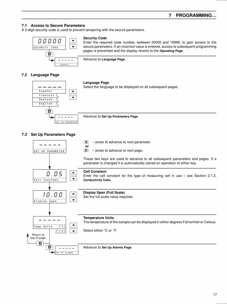
7.1 Access to Secure ParametersA 5-digit security code is used to prevent tampering with the secure parameters.
7.2 Language Page
Security CodeEnter the required code number, between 00000 and 19999, to gain access to thesecure parameters. If an incorrect value is entered, access to subsequent programmingpages is prevented and the display reverts to the Operating Page.
Advance to Language Page.
Language PageSelect the language to be displayed on all subsequent pages.
Advance to Set Up Parameters Page.
7.3 Set Up Parameters Page
– press to advance to next parameter or
– press to advance to next page.
These two keys are used to advance to all subsequent parameters and pages. If aparameter is changed it is automatically stored on operation of either key.
Cell Constant:Enter the cell constant for the type of measuring cell in use – see Section 2.1.3,Conductivity Cells.
Display Span (Full Scale)Set the full scale value required.
Temperature UnitsThe temperature of the sample can be displayed in either degrees Fahrenheit or Celsius.
Select either °C or °F.
Advance to Set Up Alarms Page.
SECURITY CODE
0 0 0 0 0
Espanol
– – – – –
_ _ _ _ _
English
Deutsch
Francais
Espanol˜
SET UP PARAMETER
– – – – –
Cell Constant
0 . 0 5
Temp Units (°C)
– – – – –
(°F)
SET UP ALARMS
– – – – –
Return totop of page
Display Span
1 0 . 0 0
SET UP PARAMETER
– – – – –
7 PROGRAMMING…
18
7.4 Set Up Alarms Page
– press to advance to next parameter or
– press to advance to next page.
These two keys are used to advance to all subsequent parameters and pages. If aparameter is changed it is automatically stored on operation of either key.
Alarm 1 TypeSelect the type of alarm required. For Fail, Temp and Cond alarm types, the alarml.e.d. is off and the relay energized during normal conditions. In a fail condition, the l.e.d.is on and the relay de-energized.
Fail – The instrument alerts the operator to either a power failure or a condition thatcauses any of the error messages listed in Table 9.1 to be displayed.
Temp – The instrument alerts the operator if the temperature of the process fluidexceeds or drops below the value set in the Alarm 1 Set Point parameter,depending on the type of Alarm 1 Action selected below.
Cond – The instrument alerts the operator if the conductivity of the process fluidexceeds or drops below the value set in the Alarm 1 Set Point parameter,depending on the type of Alarm 1 Action selected below.
Off – If selected, no alarms are set and the alarm l.e.d. is off and the relay de-energized at all times.
Alarm 1 ActionFor 'Fail-safe' alarm operation the relay's alarm state must be the same as the power-down state, i.e. the relay is de-energized.For High alarm operation the relay must be energized below the alarm set point.For low alarm operation the relay must be energized above the alarm set point.The alarm l.e.d.s are illuminated in the alarm condition.Select the required alarm 1 action from the following table:
The set point band is defined as the actual value of the set point plus or minus thehysteresis value. The hysteresis value is ± 1% of the set point value displayed in the SetUp Parameters Page – see page17. Alarm action occurs if the input value is above orbelow the set point band. If the input moves within the set point band the last alarm actionis maintained.
Alarm 1 Set PointThe alarm 1 set point can be set to any value within the input range being displayed. Theset point value is subject to hysteresis as detailed above.
Set the alarm set point to the required value.
continued on next page.
mralAnoitcA
noitidnoCDELtupnIrof
tnioPteSevobA
noitidnoCDELtupnIrof
tnioPteSwoleB
noitidnoCyaleRtupnIrof
tnioPteSevobA
noitidnoCyaleRtupnIrof
tnioPteSwoleB
hgiH NO FFO dezigrene-eD dezigrenE
woL FFO NO dezigrenE dezigrene-eD
…7 PROGRAMMING
A1 Setpoint
SET UP ALARMS
– – – – –
A1 Action High
– – – – –
Low
A1 Type Fail
– – – – –
Temp
Cond
Off
Fail orOff
4 . 0 0
19
…7.4 Set Up Alarms Page
A2 Setpoint
1 . 0 0
USP Alarm Offset
0 . 2 0
USPCond or Temp
Alter Sec. Code
0 0 0 0 0
SET UP RETRANS
– – – – –
– – – – –A2 Action High
Low
A2 Type USP
– – – – –
Temp
Cond
Fai
l or
Off
Off
Fail
Return totop of page
Alarm 2 TypeRepeat as for Alarm 1 type on the previous page.
USP – The alarm setpoint changes automatically with temperature – see table 7.1.
Alarm 2 ActionRepeat as for Alarm 1 Action on the previous page.
USP Alarm Offset (Displayed only if Alarm A2 Type is set to USP)The offset enables the alarm trip point to be triggered early for increased protection. Thevalue set is deducted from the setpoint table value – see table 7.1.Set between 0.00 and 0.50 in 0.01 increments.
Alarm 2 Set Point (Displayed only if Alarm A2 Type is set to Cond or Temp)Repeat as for Alarm 1 Set Point on previous page.
Alter Security CodeSet the security code to a value between 00000 and 19999.
Advance to Set up Retransmission Page.
7 PROGRAMMING…
erutarepmeT(° )C
ytivitcudnoC(µ )mc/S
erutarepmeT(° )C
ytivitcudnoC(µ )mc/S
erutarepmeT(° )C
ytivitcudnoC(µ )mc/S
0 6.0 53 5.1 07 5.2
5 8.0 04 7.1 57 7.2
01 9.0 54 8.1 08 7.2
51 0.1 05 9.1 58 7.2
02 1.1 55 1.2 09 7.2
52 3.1 06 2.2 59 9.2
03 4.1 56 4.2 001 1.3
Table 7.1 – USP Alarm Setpoint Values
20
…7 PROGRAMMING
7.5 Set Up Retransmission Page
– press to advance to next parameter or
– press to advance to next page.
These two keys are used to advance to all subsequent parameters and pages. If aparameter is changed it is automatically stored on operation of either key.
Set Up Retransmission 1
Retransmission 1 Output RangeSet the retransmission output current range for retransmission channel 1.
Retransmission 1 SpanSet the required span over which the retransmission output is to operate to between 10and 100% of the display span – see Section 7.3, Set Up Parameters Page.
Continued on next page.
SET UP RETRANS
– – – – –
Set Up Retrans 1
– – – – –
RTX Type 4-20
0-20
0-10
– – – – –
RTX Span µS/cm
100 . 0
21
7 PROGRAMMING
…7.5 Set Up Retransmission Page
Set Up Retransmission 2
Note. Available only on 4623/800 and 4628/800 instruments.
Retransmission 2 Output RangeSet the retransmission output current range for retransmission channel 2.
Retransmission 2 Output AssignmentSelect the Retransmission output required:
Temp – TemperatureCond – Conductivity
Retransmission 2 SpanSet the required span over which the retransmission output is to operate to between 10and 100% of the display span – see Section 7.3, Set Up Parameters Page.
Retransmission 2 ZeroSet the zero point for the retransmission 2 output.
Test Retransmission OutputThe instrument automatically transmits a test signal of 0, 25, 50, 75 or 100% of theretransmission range selected above. The % test signal selected is shown on the upperdisplay.
Example – for a selected range of 0 to 20mA and 50% retransmission test signal, 10mAis transmitted.
Select the required retransmission test signal.
Advance to Factory Settings Page.
Set Up Retrans 2
– – – – –
RTX Type 4-20
0-20
0-10
– – – – –
Cond
– – – – –RTX O/P Temp
RTX Span µS/cm
RTX Zero µS/cm
Test Retrans (%)
TempCond
FACTORY SETTINGS
– – – – –Return to
top of page
0 . 0
0 . 0
1 00 . 0
22
Note. The instrument is calibrated by the Company prior to despatch and recalibration should be carried out:
• Only if the instrument's accuracy is suspect and suitably calibrated test equipment is available.
• At 12 monthly intervals for re-validation provided suitably calibrated test equipment is available.
8.1 Equipment Requireda) Decade resistance box (cell input simulator): 0 to 10KΩ (in increments of 0.1Ω), accuracy ±0.1%.
b) Decade resistance box (temperature input simulator): 0 to 1KΩ (in increments of 0.01Ω), accuracy ±0.1%.
c) Digital milliammeter (current output measurement): 0 to 20mA.
Note.
• Resistance boxes have an inherent residual resistance which may range from a few mΩ up to 1 ohm. This value must betaken into account when simulating input levels, as should the overall tolerance of the resistors within the boxes.
• All test equipment must be traceable, with valid test certification.
8.2 Preparationa) Switch off the supply and disconnect the conductivity cell, temperature compensator and current output from the instrument's
terminal blocks – see Fig. 4.4 (page 10) or Fig. 4.5 (page 11).
b) Connect the decade boxes to the appropriate terminals – see Table 8.1. Ensure the earth on the conductivity decade box isconnected to the case earth (ground) stud. Connect the milliammeter to the retransmission output terminals – see Fig 4.4(page 10) or Fig. 4.5 (page11).
c) Switch on the supply and allow ten minutes for the circuits to stabilize.
d) Select the FACTORY SETTINGS page and carry out Section 8.3.
8 CALIBRATION
epyTtnemurtsnI rebmuNlanimreT
detnuom-llaW 1 2 3 4 5 6 7
detnuom-lenaP 21 11 01 9 8 7 6
– –edortcelelleC
tupniedortcelelleC
tupni * tupni001TPotkniL
)6(7lanimrettupni001TP
* .duts)dnuorg(htraeesacotkniL
Table 8.1 Test Equipment Connections
23
Factory Settings Access CodeEnter the required code number, between 00000 and 19999, to gain access to thefactory settings. If an incorrect value is entered, access to subsequent parameters isprevented and the display reverts to the top of the Factory Settings Page.
Electrical CalibrationSelect Yes to access the electrical calibration sequence. Select No to advance toAdjust Retransmission Zero.
Caution. Do not select Yes unless instrument calibration is required.
Advance to next parameter.
Calibrate Cell Zero 1Open circuit the cell simulator and allow the instrument display to stabilize.
Advance to next parameter.
Calibrate Cell Span 1Set the cell simulator to 10KΩ and allow the instrument display to stabilize.
Advance to next parameter.
Calibrate Cell Zero 2Open circuit the cell simulator and allow the instrument display to stabilize.
Advance to next parameter.
Calibrate Cell Span 2Set the cell simulator to 1kΩ and allow the instrument display to stabilize.
Advance to next parameter.
Continued on next page.
8.3 Factory Settings PageWhen carrying out the electrical calibration procedure, the actual values denoted by xxxxx are unimportant and are usedonly to determine display reading stability.
8 CALIBRATION…
Res Zero 2 (O/C)
x x x x x
Res Span 2 (1K0)
x x x x x
Res Zero 1 (O/C)
x x x x x
Res Span 1 (10K)
x x x x x
ELECTRICAL CAL
– – – – –
Calibrate Yes
– – – – –
No
No
Advance toAdjust RTX Zero
FACTORY SETTINGS
– – – – –
FACTORY SET CODE
0 0 0 0 0
Yes
24
…8.3 Factory Settings Page
Calibrate Temperature ZeroSet the temperature simulator to 100Ω and allow the instrument display to stabilize.
Advance to next parameter.
Calibrate Temperature SpanSet the temperature simulator to 150Ω and allow the instrument display to stabilize.
Advance to next parameter.
Adjust Retransmission 1 ZeroSet the milliammeter reading to 4mA.
Note. The retransmission range selected in the Set Up Retransmission Page doesnot affect the reading.
Advance to next parameter.
Adjust Retransmission 1 SpanSet the milliammeter reading to 20mA.
Note. The retransmission range selected in the Set Up Retransmission Page doesnot affect the reading.
Advance to next parameter.
Adjust Retransmission 2 Zero (available only on 4623/800 and 4628/800 instruments)Set the milliammeter reading to 4mA.
Note. The retransmission range selected in the Set Up Retransmission Page doesnot affect the reading.
Advance to next parameter.
Adjust Retransmission 2 Span (available only on 4623/800 and 4628/800 instruments)Set the milliammeter reading to 20mA.
Note. The retransmission range selected in the Set Up Retransmission Page doesnot affect the reading.
Advance to next parameter.
Alter Factory CodeSet the factory settings access code to a value between 00000 and 19999.
9.1 Error MessagesIf erroneous or unexpected results are obtained the fault maybe indicated by an error message – see Table 9.1. Howeversome faults may cause problems with instrument calibration orgive discrepancies when compared with independentlaboratory measurements.
Table 9.1 Error Messages
9.2 No Response to Conductivity ChangesThe majority of problems are associated with the conductivitycell, which must be cleaned as an initial check. It is alsoimportant that all program parameters have been set correctlyand have not been altered inadvertently – see Section 7.
If the above checks do not resolve the fault:
a) Check that the instrument responds to a resistance input.Disconnect the conductivity cell cable and connect asuitable resistance box directly to the transmitter input –see Section 4.3 or 4.4. Check that the instrument displaysthe correct values as set on the resistance box usingTable 9.2 below or the expression:
R =K x 106
G
Where: R = equivalent resistance
K = cell constant
G = conductivity
9 SIMPLE FAULT FINDING
Failure to respond to the input indicates a fault with theinstrument which must be returned to the Company for repair.Correct response, but with incorrect readings, usuallyindicates an electrical calibration problem. Re-calibrate theinstrument as detailed in Section 8.3.
b) If the response in a) is correct, reconnect the conductivitycell cable and connect the resistance box to the cell end.Check that the instrument displays the correct values asset on the resistance box in this configuration.
If the instrument passes check a) but fails check b), check thecable connections and condition. If the response for bothchecks is correct, replace the conductivity cell.
9.3 Checking the Temperature InputCheck that the instrument responds to a temperature input.Disconnect the PT100 leads and connect a suitable resistancebox directly to the transmitter inputs – see Section 4.3 or 4.4.Check that the transmitter displays the correct values as set onthe resistance box – see Table 9.3.
Incorrect readings usually indicate an electrical calibrationproblem – re-calibrate the instrument as detailed in Section 8.3.
Curve 'a' – Theoretical ultra-pure water conductivity
Curve 'b' – High purity water conductivity (ultra-purewater with slight impurity)
'a'
25
A1 Automatic Temperature CompensationAt high purity water conductivity levels, the conductivity/temperature relationship is made up of two components: thefirst component, due to the impurities present, generally has atemperature coefficient of approximately 0.02/°C; and thesecond, which arises from the effect of the H+ and OH– ions,becomes predominant as the ultra-pure water level isapproached.
Consequently, to achieve full automatic temperaturecompensation, the above two components must becompensated for separately, according to the followingexpression:
G25 =Gt – Gupw
[1 + ∝ (t – 25)]+ 0.055
Where: Gt = conductivity at temperature t°C
Gupw = ultra-pure water conductivity attemperature t°C
∝ = impurity temperature coefficient
0.055 = conductivity in µS/cm of ultra-purewater at 25°C
The expression is simplified as follows:
G25 =Gimp
[1 + ∝ (t – 25)]+ 0.055
Where: Gimp = impurity conductivity at temperature t°C
The above expression was solved in earlier analoginstrumentation by using two temperature sensing elementslocated in the conductivity measuring cell. However, models4623 and 4628 now utilize the computational ability of amicroprocessor to achieve ultra-pure water temperaturecompensation using only a single platinum resistancethermometer and mathematically calculating the temperaturecompensation required to give the correct conductivity at thereference temperature.
APPENDICES
Fig. A1 Theoretical Ultra-pure Water Conductivity andHigh Purity Water Conductivity v Temperature
28
NOTES
PRODUCTS & CUSTOMER SUPPORT
ProductsAutomation Systems
• for the following industries:– Chemical & Pharmaceutical– Food & Beverage– Manufacturing– Metals and Minerals– Oil, Gas & Petrochemical– Pulp and Paper
Drives and Motors• AC and DC Drives, AC and DC Machines, AC motors to 1kV• Drive systems• Force Measurement• Servo Drives
Controllers & Recorders• Single and Multi-loop Controllers• Circular Chart , Strip Chart and Paperless Recorders• Paperless Recorders• Process Indicators
Flexible Automation• Industrial Robots and Robot Systems
Flow Measurement• Electromagnetic Magnetic Flowmeters• Mass Flow Meters• Turbine Flowmeters• Wedge Flow Elements
Marine Systems & Turbochargers• Electrical Systems• Marine Equipment• Offshore Retrofit and Referbishment
Process Analytics• Process Gas Analysis• Systems Integration
ABB Automation provides a comprehensive after sales servicevia a Worldwide Service Organization. Contact one of thefollowing offices for details on your nearest Service and RepairCentre.
United KingdomABB Automation LtdTel: +44 (0)1453-826-661Fax: +44 (0)1453-827-856
United States of AmericaABB Automation Inc.Instrumentation DivisionTel: +1 215-674-6000Fax: +1 215-674-7183
Client Warranty
Prior to installation, the equipment referred to in this manualmust be stored in a clean, dry environment, in accordance withthe Company's published specification. Periodic checks must bemade on the equipment's condition.
In the event of a failure under warranty, the followingdocumentation must be provided as substantiation:
1. A listing evidencing process operation and alarm logs at timeof failure.
2. Copies of operating and maintenance records relating to thealleged faulty unit.
IM/4
600–
US
PIs
sue
3
The Company’s policy is one of continuous productimprovement and the right is reserved to modify the informationcontained herein without notice.


![Evaluation of Coating Degradation on Truss of Maubin ...iieng.org/images/proceedings_pdf/F0418119.pdfB. Evaluation of Degradation of Existing Coating [ISO 4628:2003] ISO 4628 defines](https://static.documents.pub/doc/80x56/60ec4e09ca546d350c54b995/evaluation-of-coating-degradation-on-truss-of-maubin-iiengorgimagesproceedingspdf.jpg)


