Micro-Tech,® ODEP ® and TEF ® are registered trademarks of Crown International, Inc. Other trademarks arethe property of their respective owners.
®
®
CommercialAudioLL 32521C(MT-600 & 1200)
120 VAC NorthAmerican
Units Only:
CommercialAudioE106377(MT-600 & 1200)
Approved forTHX TheatreSystems(MT-600 & 1200) ®
ForCanada(MT-2400)
WORLDWIDESUMMARY OF WARRANTY
The Crown Audio Division of Crown International, Inc., 1718 WestMishawaka Road, Elkhart, Indiana 46517-4095 U.S.A. warrants to you,the ORIGINAL PURCHASER and ANY SUBSEQUENT OWNER of eachNEW Crown1 product, for a period of three (3) years from the date ofpurchase by the original purchaser (the “warranty period”) that the newCrown product is free of defects in materials and workmanship, and wefurther warrant the new Crown product regardless of the reason forfailure, except as excluded in this Crown Warranty.1 Note: If your unit bears the name “Amcron,” please substitute it for thename “Crown” in this warranty.
ITEMS EXCLUDED FROM THIS CROWN WARRANTYThis Crown Warranty is in effect only for failure of a new Crown productwhich occurred within the Warranty Period. It does not cover any productwhich has been damaged because of any intentional misuse, accident,negligence, or loss which is covered under any of your insurancecontracts. This Crown Warranty also does not extend to the new Crownproduct if the serial number has been defaced, altered, or removed.
WHAT THE WARRANTOR WILL DOWe will remedy any defect, regardless of the reason for failure (exceptas excluded), by repair, replacement, or refund. We may not elect refundunless you agree, or unless we are unable to provide replacement, andrepair is not practical or cannot be timely made. If a refund is elected, thenyou must make the defective or malfunctioning product available to usfree and clear of all liens or other encumbrances. The refund will be equalto the actual purchase price, not including interest, insurance, closingcosts, and other finance charges less a reasonable depreciation on theproduct from the date of original purchase. Warranty work can only beperformed at our authorized service centers. We will remedy the defectand ship the product from the service center within a reasonable timeafter receipt of the defective product at our authorized service center.
HOW TO OBTAIN WARRANTY SERVICEYou must notify us of your need for warranty service not later than ninety(90) days after expiration of the warranty period. All components must beshipped in a factory pack. Corrective action will be taken within areasonable time of the date of receipt of the defective product by ourauthorized service center. If the repairs made by our authorized servicecenter are not satisfactory, notify our authorized service centerimmediately.
DISCLAIMER OF CONSEQUENTIAL AND INCIDENTAL DAMAGESYOU ARE NOT ENTITLED TO RECOVER FROM US ANY INCIDENTALDAMAGES RESULTING FROM ANY DEFECT IN THE NEW CROWNPRODUCT. THIS INCLUDES ANY DAMAGE TO ANOTHER PRODUCTOR PRODUCTS RESULTING FROM SUCH A DEFECT.
WARRANTY ALTERATIONSNo person has the authority to enlarge, amend, or modify this CrownWarranty. This Crown Warranty is not extended by the length of timewhich you are deprived of the use of the new Crown product. Repairs andreplacement parts provided under the terms of this Crown Warranty shallcarry only the unexpired portion of this Crown Warranty.
DESIGN CHANGESWe reserve the right to change the design of any product from time to timewithout notice and with no obligation to make corresponding changes inproducts previously manufactured.
LEGAL REMEDIES OF PURCHASERNo action to enforce this Crown Warranty shall be commenced later thanninety (90) days after expiration of the warranty period.
THIS STATEMENT OF WARRANTY SUPERSEDES ANY OTHERSCONTAINED IN THIS MANUAL FOR CROWN PRODUCTS.
9/90
NORTH AMERICASUMMARY OF WARRANTY
The Crown Audio Division of Crown International, Inc., 1718 West MishawakaRoad, Elkhart, Indiana 46517-4095 U.S.A. warrants to you, the ORIGINALPURCHASER and ANY SUBSEQUENT OWNER of each NEW Crown prod-uct, for a period of three (3) years from the date of purchase by the originalpurchaser (the “warranty period”) that the new Crown product is free of defectsin materials and workmanship. We further warrant the new Crown productregardless of the reason for failure, except as excluded in this Warranty.
ITEMS EXCLUDED FROM THIS CROWN WARRANTYThis Crown Warranty is in effect only for failure of a new Crown product whichoccurred within the Warranty Period. It does not cover any product which hasbeen damaged because of any intentional misuse, accident, negligence, orloss which is covered under any of your insurance contracts. This CrownWarranty also does not extend to the new Crown product if the serial numberhas been defaced, altered, or removed.
WHAT THE WARRANTOR WILL DOWe will remedy any defect, regardless of the reason for failure (except asexcluded), by repair, replacement, or refund. We may not elect refund unlessyou agree, or unless we are unable to provide replacement, and repair is notpractical or cannot be timely made. If a refund is elected, then you must makethe defective or malfunctioning product available to us free and clear of all liensor other encumbrances. The refund will be equal to the actual purchase price,not including interest, insurance, closing costs, and other finance charges lessa reasonable depreciation on the product from the date of original purchase.Warranty work can only be performed at our authorized service centers or atthe factory. We will remedy the defect and ship the product from the servicecenter or our factory within a reasonable time after receipt of the defectiveproduct at our authorized service center or our factory. All expenses inremedying the defect, including surface shipping costs in the United States,will be borne by us. (You must bear the expense of shipping the productbetween any foreign country and the port of entry in the United States and alltaxes, duties, and other customs fees for such foreign shipments.)
HOW TO OBTAIN WARRANTY SERVICEYou must notify us of your need for warranty service not later than ninety (90)days after expiration of the warranty period. All components must be shippedin a factory pack, which, if needed, may be obtained from us free of charge.Corrective action will be taken within a reasonable time of the date of receiptof the defective product by us or our authorized service center. If the repairsmade by us or our authorized service center are not satisfactory, notify us orour authorized service center immediately.
DISCLAIMER OF CONSEQUENTIAL AND INCIDENTAL DAMAGESYOU ARE NOT ENTITLED TO RECOVER FROM US ANY INCIDENTALDAMAGES RESULTING FROM ANY DEFECT IN THE NEW CROWNPRODUCT. THIS INCLUDES ANY DAMAGE TO ANOTHER PRODUCT ORPRODUCTS RESULTING FROM SUCH A DEFECT. SOME STATES DONOT ALLOW THE EXCLUSION OR LIMITATIONS OF INCIDENTAL ORCONSEQUENTIAL DAMAGES, SO THE ABOVE LIMITATION OREXCLUSION MAY NOT APPLY TO YOU.
WARRANTY ALTERATIONSNo person has the authority to enlarge, amend, or modify this Crown Warranty.This Crown Warranty is not extended by the length of time which you aredeprived of the use of the new Crown product. Repairs and replacement partsprovided under the terms of this Crown Warranty shall carry only the unexpiredportion of this Crown Warranty.
DESIGN CHANGESWe reserve the right to change the design of any product from time to timewithout notice and with no obligation to make corresponding changes inproducts previously manufactured.
LEGAL REMEDIES OF PURCHASERTHIS CROWN WARRANTY GIVES YOU SPECIFIC LEGAL RIGHTS, YOUMAY ALSO HAVE OTHER RIGHTS WHICH VARY FROM STATE TO STATE.No action to enforce this Crown Warranty shall be commenced later thanninety (90) days after expiration of the warranty period.
THIS STATEMENT OF WARRANTY SUPERSEDES ANY OTHERSCONTAINED IN THIS MANUAL FOR CROWN PRODUCTS.
The lightning bolttriangle is used toalert the user to therisk of electric shock.
The exclamation pointtriangle is used to alert theuser to important operating ormaintenance instructions.
WARNINGTO REDUCE THE RISK OF ELECTRIC
SHOCK, DO NOT EXPOSE THISEQUIPMENT TO RAIN OR MOISTURE!
Magnetic FieldCAUTION! Do not locate sensitive high-gain equip-ment such as preamplifiers or tape decks directlyabove or below the unit. Because this amplifier hasa high power density, it has a strong magnetic fieldwhich can induce hum into unshielded devices thatare located nearby. The field is strongest just aboveand below the unit.
If an equipment rack is used, we recommend locatingthe amplifier(s) in the bottom of the rack and thepreamplifier or other sensitive equipment at the top.
IMPORTANTTHE MICRO-TECH 2400 REQUIRES CLASS 1OUTPUT WIRING. THE MICRO-TECH 600 &1200 REQUIRE CLASS 2 OUTPUT WIRING.
The information furnished in this manual does not include all of the details of design, production, or variations ofthe equipment. Nor does it cover every possible situation which may arise during installation, operation or main-tenance. If your unit bears the name “Amcron,” please substitute it for the name “Crown” in this manual. If youneed special assistance beyond the scope of this manual, please contact our Technical Support Group.
Crown Audio Division Technical Support GroupPlant 2 SW, 1718 W. Mishawaka Rd., Elkhart, Indiana 46517 U.S.A.
Phone: 800-342-6939 (North America, Puerto Rico and Virgin Islands) or 219-294-8200Fax: 219-294-8301 Fax Back (North America only): 800-294-4094 or 219-293-9200
Fax Back (International): 219-294-8100 Internet: http://www.crownintl.com
C A U T I O NRISK OF ELECTRIC SHOCK
DO NOT OPEN
TO PREVENT ELECTRIC SHOCK DONOT REMOVE TOP OR BOTTOM
COVERS. NO USER SERVICEABLEPARTS INSIDE. REFER SERVICINGTO QUALIFIED SERVICE PERSON-NEL. DISCONNECT POWER CORDBEFORE REMOVING BACK PANELCOVER TO ACCESS GAIN SWITCH.
A V I SRISQUE DE CHOC ÉLECTRIQUE
N’OUVREZ PAS
À PRÉVENIR LE CHOC ÉLECTRIQUEN’ENLEVEZ PAS LES COUVERCLES. ILN’Y A PAS DES PARTIES SERVICEABLE
À L’INTÉRIEUR. TOUS REPARATIONSDOIT ETRE FAIRE PAR PERSONNEL
QUALIFIÉ SEULMENT. DÉBRANCHERLA BORNE AVANT D’ENLEVER LA
9 Service ........................................................................... 379.1 Worldwide Service ................................................... 379.2 North American Service ........................................... 37
9.2.1 Service at a North American Service Center .. 379.2.2 Factory Service ............................................. 37
Page 5
Micro-Tech 600/1200/2400 Power Amplifiers
ILLUSTRATIONS1.1 Micro-Tech Amplifier .................................................................. 72.1 Front Facilities ............................................................................ 82.2 Rear Facilities ............................................................................ 93.1 Mounting Dimensions .............................................................. 103.2 Top View of a Rack-Mounted Unit ............................................. 103.3 Proper Air Flow with a Rack-Mounted Blower ........................... 103.4 Stereo Wiring ........................................................................... 113.5 Bridge-Mono Wiring ................................................................. 123.6 Parallel-Mono Wiring ................................................................ 133.7 Unbalanced Input Wiring for the Optional MT-XLR ................... 143.8 Balanced Input Wiring for the Optional MT-XLR........................ 143.9 Balanced and Unbalanced Phone Plug Wiring ......................... 143.10 Subsonic Filter Capacitors ....................................................... 153.11 Unbalanced RF Filters .............................................................. 153.12 Balanced RF Filters .................................................................. 153.13 Wire Size Nomograph .............................................................. 163.14 Low-Frequency Protection Circuit for Inductive Loads ............. 173.15 Loudspeaker Fuse Nomograph ............................................... 183.16 AC Mains Cords and Plugs ...................................................... 184.1 Indicators ................................................................................. 194.2 Input Sensitivity and Ground Lift Switches ................................ 215.1 Circuit Block Diagram .............................................................. 236.1 Micro-Tech 600 Minimum Power Matrix .................................... 276.2 Micro-Tech 1200 Minimum Power Matrix .................................. 286.3 Micro-Tech 2400 Minimum Power Matrix .................................. 286.4 Micro-Tech 600 Maximum Power Matrix ................................... 296.5 Micro-Tech 1200 Maximum Power Matrix ................................. 306.6 Micro-Tech 2400 Maximum Power Matrix ................................. 306.7 Typical Frequency Response ................................................... 316.8 Typical Damping Factor ........................................................... 316.9 Typical Output Impedance ....................................................... 316.10 Typical Phase Response .......................................................... 326.11 Typical Crosstalk for the Micro-Tech 600 .................................. 326.12 Typical Crosstalk for the Micro-Tech 1200 ................................ 336.13 Typical Crosstalk for the Micro-Tech 2400 ................................ 337.1 Micro-Tech 600 Power Draw, Current Draw and Thermal
Dissipation at Various Duty Cycles ........................................... 347.2 Micro-Tech 1200 Power Draw, Current Draw and Thermal
Dissipation at Various Duty Cycles ........................................... 357.3 Micro-Tech 2400 Power Draw, Current Draw and Thermal
Dissipation at Various Duty Cycles ........................................... 358.1 MT-XLR .................................................................................... 368.2 MT-BB ...................................................................................... 36
Page 6
Micro-Tech 600/1200/2400 Power Amplifiers
Page 7
Micro-Tech 600/1200/2400 Power Amplifiers
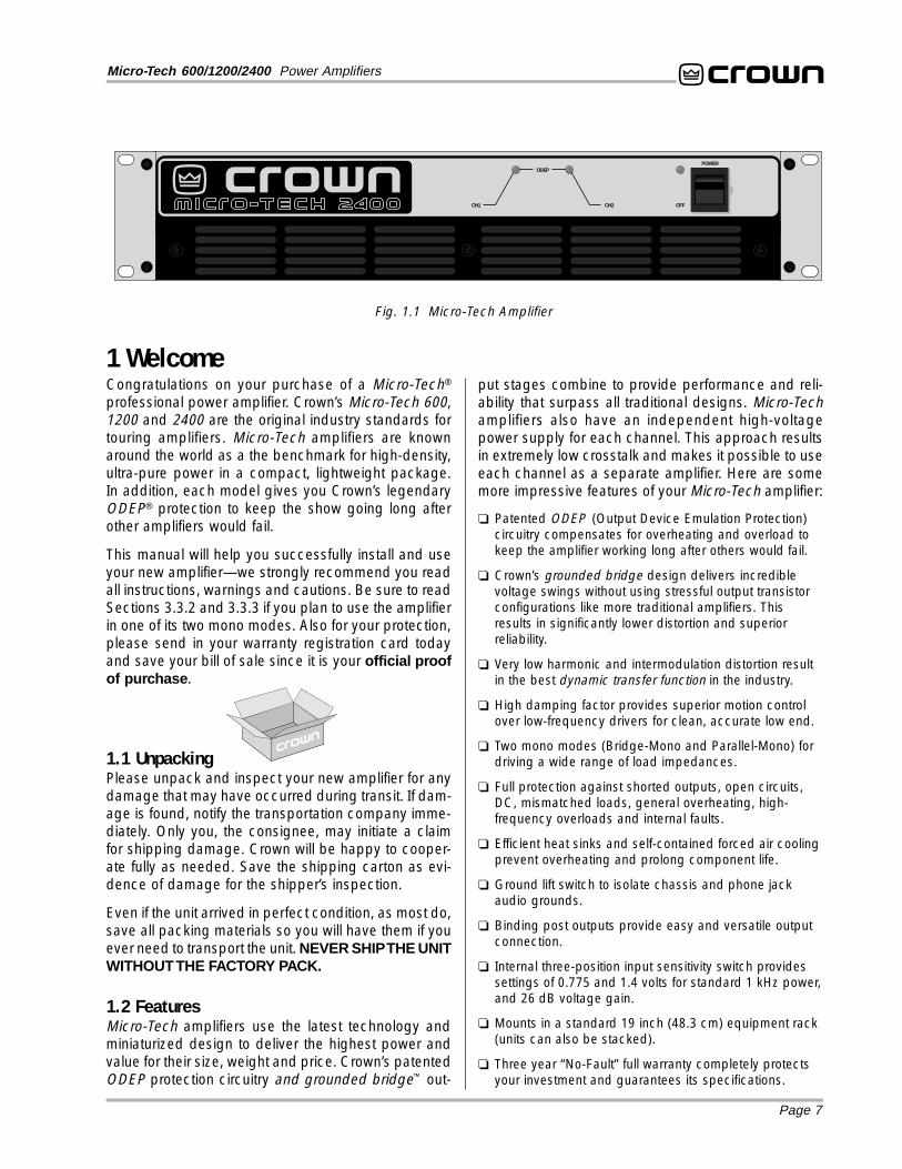
1 WelcomeCongratulations on your purchase of a Micro-Tech®
professional power amplifier. Crown’s Micro-Tech 600,1200 and 2400 are the original industry standards fortouring amplifiers. Micro-Tech amplifiers are knownaround the world as a the benchmark for high-density,ultra-pure power in a compact, lightweight package.In addition, each model gives you Crown’s legendaryODEP® protection to keep the show going long afterother amplifiers would fail.
This manual will help you successfully install and useyour new amplifier—we strongly recommend you readall instructions, warnings and cautions. Be sure to readSections 3.3.2 and 3.3.3 if you plan to use the amplifierin one of its two mono modes. Also for your protection,please send in your warranty registration card todayand save your bill of sale since it is your official proofof purchase .
1.1 UnpackingPlease unpack and inspect your new amplifier for anydamage that may have occurred during transit. If dam-age is found, notify the transportation company imme-diately. Only you, the consignee, may initiate a claimfor shipping damage. Crown will be happy to cooper-ate fully as needed. Save the shipping carton as evi-dence of damage for the shipper’s inspection.
Even if the unit arrived in perfect condition, as most do,save all packing materials so you will have them if youever need to transport the unit. NEVER SHIP THE UNITWITHOUT THE FACTORY PACK.
1.2 FeaturesMicro-Tech amplifiers use the latest technology andminiaturized design to deliver the highest power andvalue for their size, weight and price. Crown’s patentedODEP protection circuitry and grounded bridge™ out-
put stages combine to provide performance and reli-ability that surpass all traditional designs. Micro-Techamplifiers also have an independent high-voltagepower supply for each channel. This approach resultsin extremely low crosstalk and makes it possible to useeach channel as a separate amplifier. Here are somemore impressive features of your Micro-Tech amplifier:
Patented ODEP (Output Device Emulation Protection)circuitry compensates for overheating and overload tokeep the amplifier working long after others would fail.
Crown’s grounded bridge design delivers incrediblevoltage swings without using stressful output transistorconfigurations like more traditional amplifiers. Thisresults in significantly lower distortion and superiorreliability.
Very low harmonic and intermodulation distortion resultin the best dynamic transfer function in the industry.
High damping factor provides superior motion controlover low-frequency drivers for clean, accurate low end.
Two mono modes (Bridge-Mono and Parallel-Mono) fordriving a wide range of load impedances.
Full protection against shorted outputs, open circuits,DC, mismatched loads, general overheating, high-frequency overloads and internal faults.
Efficient heat sinks and self-contained forced air coolingprevent overheating and prolong component life.
Ground lift switch to isolate chassis and phone jackaudio grounds.
Binding post outputs provide easy and versatile outputconnection.
Internal three-position input sensitivity switch providessettings of 0.775 and 1.4 volts for standard 1 kHz power,and 26 dB voltage gain.
Mounts in a standard 19 inch (48.3 cm) equipment rack(units can also be stacked).
Three year “No-Fault” full warranty completely protectsyour investment and guarantees its specifications.
ODEP
CH1 CH2
POWER
OFF
Fig. 1.1 Micro-Tech Amplifier
Page 8
Micro-Tech 600/1200/2400 Power Amplifiers
Fig. 2.1 Front Facilities
ODEP
CH1 CH2
POWER
OFF
A B C C D
2 FacilitiesA. Filter GrilleThis metal grille supports and protects the dustfilter (B). To clean the dust filter, detach the grille byremoving the three screws that hold it in place.
B. Dust FilterThe dust filter removes large particles from the airdrawn by the cooling fan. Check the filter regularly toprevent clogging (see Sections 3.2 and 4.5).
C. ODEP IndicatorsDuring normal operation of the Output Device Emula-tion Protection circuitry, these amber indicators glowbrightly to show that reserve thermodynamic energy ispresent. They dim proportionally as energy reservesdecrease. In the rare event that energy reserves aredepleted, the ODEP indicators turn off and the protec-tion circuitry proportionally limits output drive so theamplifier can safely continue operating even undersevere conditions. These indicators also help identifymore unusual operating conditions (see Section 4.2).
D. Enable IndicatorThis indicator lights when the amplifier is turned on, ACpower is available and the low-voltage power supplyand fan are operational (see Section 4.2).
E. Power SwitchThis rocker switch is used to turn the amplifier on andoff. When turned on, the output is muted for approxi-mately four seconds to protect your system from start-up transients. (To change the start-up delay time,contact Crown’s Technical Support Group.)
F. Power CordAll units are shipped with an appropriate plug and cordfor the required AC voltage (see Figure 3.16). Also, re-fer to Section 7 for power usage information.
G. Stereo/Mono SwitchThe amplifier’s three operating modes are controlledby this switch. Use Stereo mode for normal two-chan-nel operation, Bridge-Mono mode to drive a singlechannel with a load impedance of at least 4 ohms, andParallel-Mono mode to drive a single channel with aload impedance less than 4 ohms. Important: Turn offthe amplifier before changing the stereo/monoswitch (see Section 3.3).
H. Reset Switches (Micro-Tech 2400 only)The Micro-Tech 2400 has two push-button resetswitches on the back panel that are used to reset thecircuit breakers for the high-voltage power supplies.
Page 9
Micro-Tech 600/1200/2400 Power Amplifiers
Fig. 2.2 Rear Facilities
CAUTION:THIS COVER IS NECESSARY FOREFFICIENT COOLING OF THE AMPLIFIER.REMOVE ONLY TO ACCESS GAIN SWITCH.
(AFFECTS PHONE INPUTS ONLY.)CAUTION: TURN OFF AMPLIFIER
BEFORE CHANGING THIS SWITCH!
STEREO
BRIDGEMONO
PARALLELMONO
CLASS 1OUTPUTWIRING
REQUIRED.
WARNING: TO REDUCE THE RISK OF FIRE ORELECTRIC SHOCK DO NOT EXPOSE THIS EQUIPMENTTO RAIN OR MOISTURE.
OUTPUTS
LIFTREG. U.S. PAT. OFF.
4,330,8094,611,180
MODEL: MICRO-TECH 2400 SERIES AC VOLTS: 120 AMPS: 17 60 Hz
MAXIMUM OUTPUT: 900 WATTSPER CHANNEL INTO 2 OHMS AT 1 KHzWITH NO MORE THAN 0.1% THD.
UNBALANCEDINPUT WIRING
BALANCEDINPUT WIRING
+–
TIP
RING
SLEEVEGND
+ TIP
SLEEVEGND
CH-2
(MONO)INPUTGAIN
CH-1
INPUT GAIN
THIS AMPLIFIER IS EQUIPPED WITH SELECTABLE INPUT SENSITIVITY. REMOVE COVER PLATE (ABOVE) TO ACCESS SENSITIVITY SWITCH.
® INTERNATIONAL, INC.ELECTRONIC EQUIPMENT
ELKHART, IN 46517MADE IN U.S.A.
SERIAL NUMBER
0000
000000
F G H I K KL M MJJ
PUSH TO RESET
I. Cover PlateThis cover plate is removed when changing theamplifier’s input sensitivity (see Section 4.4) or install-ing an MT-XLR or MT-BB accessory (see Section 8.2).
Input Sensitivity SwitchThe three-position input sensitivity switch is located in-side the amplifier behind the cover plate (I). Settingsinclude 0.775 volts and 1.4 volts for standard 1 kHzpower, and 26 dB gain (see Section 4.4).
J. Level ControlsThese back panel level controls are used to set theamplifier’s output levels (see Section 4.4). Be sure toturn down the channel 2 level control (fully counter-clockwise) when operating in Bridge-Mono mode.
K. Balanced Phone Jack InputsA balanced ¼-inch phone jack input is provided for
each channel. They may be wired for balanced (tip,ring and sleeve) or unbalanced (tip and sleeve) opera-tion (refer to Section 3.3.4). XLR and barrier block in-put connectors are available with the MT-XLR andMT-BB accessories (see Section 8.2). Caution: Do notuse the channel 2 input in either mono mode.
L. Ground Lift SwitchThis switch is used to isolate the phone jack signalgrounds from the AC power (chassis) ground. Movingthe switch to the “lift” position helps prevent the humassociated with ground loops (see Section 4.4).
M. Output JacksA pair of versatile binding posts is provided for outputconnection to each channel. Loudspeakers can beeasily connected using banana plugs, spade lugs orbare wire (European models do not accept bananaplugs). See Section 3.3.
Page 10
Micro-Tech 600/1200/2400 Power Amplifiers
3 Installation3.1 MountingMicro-Tech amplifiers are designed for standard 19-inch (48.3 cm) rack mounting or stacking without acabinet. In a rack, it is best to mount units directly ontop of each other. This provides the most efficient airflow and support. If the rack will be transported, werecommend that you provide support for the amplifier’sback panel or secure it to the rack to help support theunit’s weight.
Fig. 3.1 Mounting Dimensions
ODEP
CH1 CH2
POWER
OFF
19 in48.3 cm
16 in40.6 cm
3.5 in8.9 cm
SIDE VIEW
Fig. 3.2 Top View of a Rack-Mounted Unit
AIRFLOW
AIR FLOW
AMPLIFIER(TOP VIEW)
RACKCABINET
16 in
2 inMIN.
17 in
AIRFLOW
IMPORTANT: Be sure the back ofthe amplifier is supported.
3.2 CoolingMicro-Tech amplifiers include an internal fan that runswhen the unit is turned on. Before mounting your am-plifier, you should familiarize yourself with its coolingrequirements.
Here are some tips to help keep your amplifier cool.First, never block the amplifier’s front or side air vents.If the amplifier is rack-mounted, its sides should be atleast 2 inches (5 cm) away from the cabinet (see Fig-ure 3.2). Also, open spaces in the rack should be cov-ered to prevent heated air from the side exhaust ventsfrom being drawn into the front air intake.
BLOWER(OPTION 2)
BLOWER(OPTION 1)
AIRFLOW
FRONTOF
RACK
DOOR
AIRFLOW
EQUIPMENTRACK
(SIDE VIEW)
Fig. 3.3 Proper Air Flow with a Rack-Mounted Blower
You will know when your Micro-Tech amplifier has suffi-cient cooling because its ODEP indicators will bebrightly lit. If the amplifier’s ODEP indicators dim or turnoff, overly demanding conditions are forcing it to pro-tect itself from overheating. If you experience a coolingproblem, you should consider several factors that maybe contributing to the problem, including load imped-ance, air flow and ambient air temperature.
Low-impedance loads generate more heat than higherimpedance loads. To avoid impedance-related coolingproblems, connect loads to each channel with a totalimpedance of at least 2 ohms in Stereo, 4 ohms inBridge-Mono, and 1 ohm in Parallel-Mono mode (seeSection 3.3 for wiring instructions). If your loads arereasonable and you still have a cooling problem, checkfor shorts in the loudspeaker cables, and look for prob-lems with air flow or ambient air temperature.
Air flow restrictions are the most common cause of in-adequate cooling. They may result from impropermounting, bundles of power cords, clogged dust fil-ters and closed rack doors. Mount the amplifier to al-low sufficient air flow into the front intake, out the sideexhaust vents, and out the back of the rack. Move airflow restrictions like bundled power cords out of theway. Use the procedure in Section 4.5 to clean the airfilters. Leave rack doors open, remove them, or installa grille. If you install a grille, we recommend using awire grille because perforated panels restrict air flowby at least 40%.
If your ODEP indicators still dim under demanding con-ditions, you may want to install supplemental coolinglike a rack-mounted blower or an air conditioner. A“squirrel cage” blower can be installed at the bottom of
Page 11
Micro-Tech 600/1200/2400 Power Amplifiers
the rack so it blows outside air into the space betweenthe door and the front of the amplifiers. This will pres-surize the “chimney” behind the door (Figure 3.3, Op-tion 1). The blower should not blow air into or take airout of the space behind the amplifiers. For racks with-out a front door, you can evacuate the rack by mount-ing the blower at the top of the rack so air blows out theback (Figure 3.3, Option 2). You can estimate a rack’srequired air flow by adding each unit’s maximum airflow rating. Each Micro-Tech 600 and 1200 can move35 cubic feet (1 cubic meter) of air per minute, andeach Micro-Tech 2400 can move 45 cubic feet (1.3cubic meters) of air per minute. So if you put one ofeach in a rack, you would need 115 cubic feet (3.2 cu-bic meters) of air flow through the rack per minute un-der worst-case conditions (35 cubic feet + 35 cubicfeet + 45 cubic feet = 115 cubic feet).
Another cooling problem to consider is high ambientair temperature. If the ambient air temperature is ex-tremely high, ODEP may reduce the output to protectthe amplifier even when it is receiving the maximumrecommended air flow. Under these unusual condi-tions, it may be necessary to use air conditioning forsupplemental cooling. Air conditioning is rarely a ne-cessity because internal fans and rack-mounted blow-ers almost always provide enough air flow for the mostextreme conditions. Still, air conditioning helps reducethe ambient temperature of the air flowing through therack. If you plan to use air conditioning, refer to Sec-tion 7 for information on calculating the hourly thermaldissipation of your system.
3.3 WiringThe following section describes common ways to in-stall your amplifier in a sound system. The input andoutput terminals are located on the back panel. Pleaseuse care when making connections, selecting signalsources and controlling the output level. The load yousave may be your own! Crown assumes no liability fordamaged loads resulting from careless amplifier useor deliberate overpowering.
CAUTION: When making or changing connections,always disconnect the AC power and turn the levelcontrols off (fully counterclockwise). This is very im-portant because it reduces the chance of loud blaststhat can cause loudspeaker damage.
Micro-Tech amplifiers may be operated in one of threemodes (Stereo, Bridge-Mono and Parallel-Mono) byswitching the stereo/mono switch on the back panel.There are VERY IMPORTANT wiring differences amongthese three modes which are discussed next.
3.3.1 Stereo (Two-Channel) OperationIn Stereo mode, installation is very intuitive: input chan-nel 1 feeds output channel 1, and input channel 2 feedsoutput channel 2. To put the amplifier into Stereo mode,first turn it off, then slide the stereo/mono switch to thecenter position, and properly connect the output wir-ing as shown in Figure 3.4. Each channel has a pair ofbinding posts for easy loudspeaker cable connection.Observe correct polarity, and be very careful not toshort the two channels together.
Fig. 3.4 Stereo Wiring
STEREO MODE
MIXER LOUDSPEAKERS
MICRO-TECH AMPLIFIER
+
–
+
–
CHANNEL 1
CHANNEL 2
CHANNEL 1
CHANNEL 2
STEREO
BRIDGEMONO
PARALLELMONO
CAUTION: TURN OFF AMPLIFIERBEFORE CHANGING THIS SWITCH.
STEREO
BRIDGEMONO
PARALLELMONO
CH-2 CH-1
CH.2LEVEL
CONTROL
GROUNDLIFT
SWITCH
CH.1LEVEL
CONTROL
Page 12
Micro-Tech 600/1200/2400 Power Amplifiers
CAUTION: In Stereo mode, never tie the amplifier’soutputs directly together, and never parallel themwith the output of another amplifier. Such connec-tions do not increase the output power and may acti-vate the protection circuitry to prevent overheating.
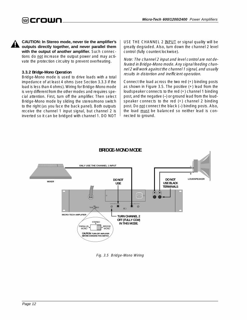
3.3.2 Bridge-Mono OperationBridge-Mono mode is used to drive loads with a totalimpedance of at least 4 ohms (see Section 3.3.3 if theload is less than 4 ohms). Wiring for Bridge-Mono modeis very different from the other modes and requires spe-cial attention. First, turn off the amplifier. Then selectBridge-Mono mode by sliding the stereo/mono switchto the right (as you face the back panel). Both outputsreceive the channel 1 input signal, but channel 2 isinverted so it can be bridged with channel 1. DO NOT
USE THE CHANNEL 2 INPUT or signal quality will begreatly degraded. Also, turn down the channel 2 levelcontrol (fully counterclockwise).
Note: The channel 2 input and level control are not de-feated in Bridge-Mono mode. Any signal feeding chan-nel 2 will work against the channel 1 signal, and usuallyresults in distortion and inefficient operation.
Connect the load across the two red (+) binding postsas shown in Figure 3.5. The positive (+) lead from theloudspeaker connects to the red (+) channel 1 bindingpost, and the negative (–) or ground lead from the loud-speaker connects to the red (+) channel 2 bindingpost. Do not connect the black (–) binding posts. Also,the load must be balanced so neither lead is con-nected to ground.
MIXERLOUDSPEAKER
–
+
ONLY USE THE CHANNEL 1 INPUT
DO NOTUSE
DO NOTUSE BLACKTERMINALS
STEREO
BRIDGEMONO
PARALLELMONO
CAUTION: TURN OFF AMPLIFIERBEFORE CHANGING THIS SWITCH.
STEREO
BRIDGEMONO
PARALLELMONO
CH-2 CH-1
TURN CHANNEL 2OFF (FULLY CCW)
IN THIS MODE.
MICRO-TECH AMPLIFIER
Fig. 3.5 Bridge-Mono Wiring
BRIDGE-MONO MODE
Page 13
Micro-Tech 600/1200/2400 Power Amplifiers
CAUTION: Only connect balanced equipment(meters, switches, etc.) to the Bridge-Mono output.Both sides of the line must be isolated from the in-put grounds or oscillations may occur.
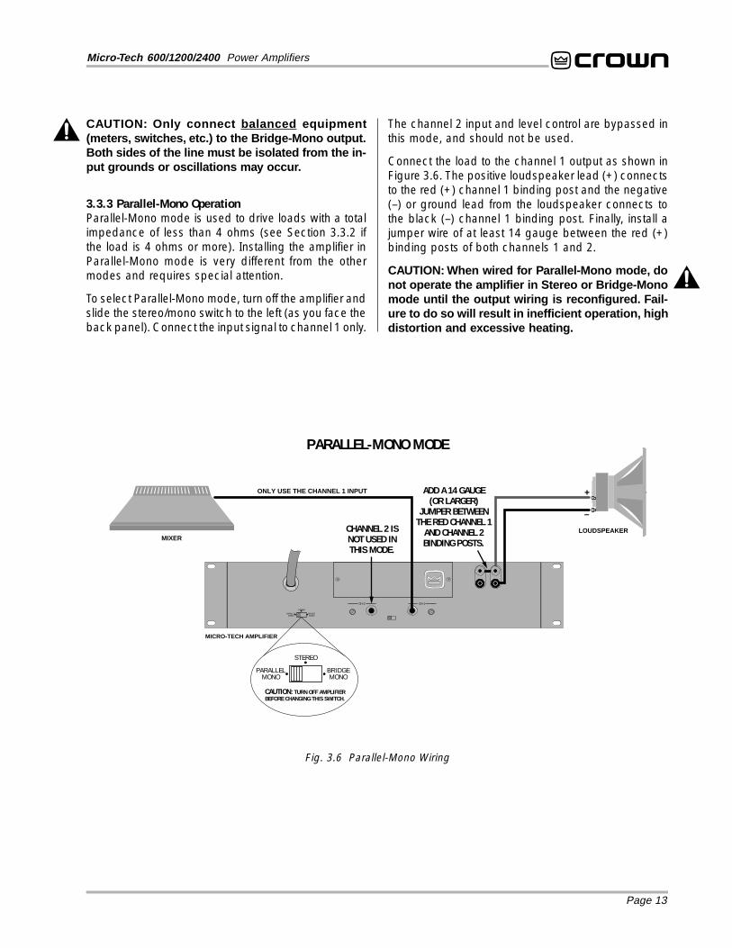
3.3.3 Parallel-Mono OperationParallel-Mono mode is used to drive loads with a totalimpedance of less than 4 ohms (see Section 3.3.2 ifthe load is 4 ohms or more). Installing the amplifier inParallel-Mono mode is very different from the othermodes and requires special attention.
To select Parallel-Mono mode, turn off the amplifier andslide the stereo/mono switch to the left (as you face theback panel). Connect the input signal to channel 1 only.
Fig. 3.6 Parallel-Mono Wiring
MIXERLOUDSPEAKER
–
+ONLY USE THE CHANNEL 1 INPUT
CHANNEL 2 ISNOT USED INTHIS MODE.
MICRO-TECH AMPLIFIER
STEREO
BRIDGEMONO
PARALLELMONO
CAUTION: TURN OFF AMPLIFIERBEFORE CHANGING THIS SWITCH.
STEREO
BRIDGEMONO
PARALLELMONO
CH-2 CH-1
ADD A 14 GAUGE(OR LARGER)
JUMPER BETWEENTHE RED CHANNEL 1
AND CHANNEL 2BINDING POSTS.
PARALLEL-MONO MODE
The channel 2 input and level control are bypassed inthis mode, and should not be used.
Connect the load to the channel 1 output as shown inFigure 3.6. The positive loudspeaker lead (+) connectsto the red (+) channel 1 binding post and the negative(–) or ground lead from the loudspeaker connects tothe black (–) channel 1 binding post. Finally, install ajumper wire of at least 14 gauge between the red (+)binding posts of both channels 1 and 2.
CAUTION: When wired for Parallel-Mono mode, donot operate the amplifier in Stereo or Bridge-Monomode until the output wiring is reconfigured. Fail-ure to do so will result in inefficient operation, highdistortion and excessive heating.
Page 14
Micro-Tech 600/1200/2400 Power Amplifiers
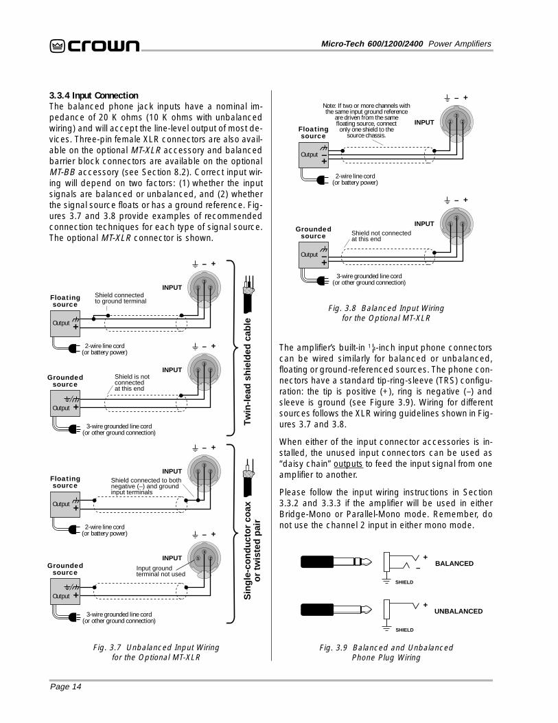
3.3.4 Input ConnectionThe balanced phone jack inputs have a nominal im-pedance of 20 K ohms (10 K ohms with unbalancedwiring) and will accept the line-level output of most de-vices. Three-pin female XLR connectors are also avail-able on the optional MT-XLR accessory and balancedbarrier block connectors are available on the optionalMT-BB accessory (see Section 8.2). Correct input wir-ing will depend on two factors: (1) whether the inputsignals are balanced or unbalanced, and (2) whetherthe signal source floats or has a ground reference. Fig-ures 3.7 and 3.8 provide examples of recommendedconnection techniques for each type of signal source.The optional MT-XLR connector is shown.
Fig. 3.7 Unbalanced Input Wiringfor the Optional MT-XLR
Tw
in-le
ad s
hiel
ded
cabl
e
2-wire line cord(or battery power)
Shield connectedto ground terminal
3-wire grounded line cord(or other ground connection)
Shield is notconnectedat this end
Groundedsource
3-wire grounded line cord(or other ground connection)
Input groundterminal not used
Groundedsource
Sin
gle-
cond
ucto
r co
axor
twis
ted
pair2-wire line cord
(or battery power)
Floatingsource
Shield connected to bothnegative (–) and groundinput terminals
+–
INPUT
Output
Floatingsource
+
3
1 2
+–
INPUT
+Output
3
1 2
+–
INPUT
Output +
3
1 2
+–
+Output
INPUT
3
1 2
3
1 2
+–
INPUT
2-wire line cord(or battery power)
Note: If two or more channels withthe same input ground reference
are driven from the samefloating source, connect
only one shield to thesource chassis.
Floatingsource
3-wire grounded line cord(or other ground connection)
Shield not connectedat this end
Groundedsource
3
1 2
Output+–
+–
Output+–
INPUT
Fig. 3.8 Balanced Input Wiringfor the Optional MT-XLR
The amplifier’s built-in 1¦4-inch input phone connectorscan be wired similarly for balanced or unbalanced,floating or ground-referenced sources. The phone con-nectors have a standard tip-ring-sleeve (TRS) configu-ration: the tip is positive (+), ring is negative (–) andsleeve is ground (see Figure 3.9). Wiring for differentsources follows the XLR wiring guidelines shown in Fig-ures 3.7 and 3.8.
When either of the input connector accessories is in-stalled, the unused input connectors can be used as“daisy chain” outputs to feed the input signal from oneamplifier to another.
Please follow the input wiring instructions in Section3.3.2 and 3.3.3 if the amplifier will be used in eitherBridge-Mono or Parallel-Mono mode. Remember, donot use the channel 2 input in either mono mode.
Fig. 3.9 Balanced and UnbalancedPhone Plug Wiring
+–
SHIELD
BALANCED
+
SHIELD
UNBALANCED
Page 15
Micro-Tech 600/1200/2400 Power Amplifiers
SOLVING INPUT PROBLEMSSometimes large subsonic (subaudible) frequenciesare present in the input signal. These can damageloudspeakers by overloading or overheating them. Toattenuate such frequencies, place a capacitor in se-ries with the input signal line. The graph in Figure 3.10shows some possible capacitor values and how theyaffect frequency response. Use only low-leakage pa-per, mylar or tantalum capacitors.
+
–
Balanced In
910 Ω
.003fµ
.015fµ
.018fµ
1.8 mH
2.5 mH
A
C
B
.015fµ
1.8 mH
D
Balanced Out
+
–910 Ω
1.8 mH
2.5 mH
1.8 mH
+
–
Balanced In Balanced Out
+
–
+
–
Balanced In Balanced Out
+
–
+
–
Balanced In Balanced Out
+
–
0.47 Film
0.47 Film
1 Hz 10 Hz 100 Hz 1 kHz 10 kHz
dB
0
–5
–10
–15
Frequency
0.04
7 µf
0.1
µf
0.47
µf
1.0
µf
0.22
µf
Fig. 3.10 Subsonic Filter Capacitors
For balanced input wiring, use one of the examples inFigure 3.12. Filters A, B and C correspond to the un-balanced filters above. Filter D also incorporates thesubsonic filter described previously.
Another problem to avoid is grgrgrgrground loopsound loopsound loopsound loopsound loops. These areundesired currents that flow in a grounded system and
Fig. 3.12 Balanced RF Filters
usually cause hum in the output. A common source ofground loop problems is the placement of input cablesparallel to power cables or near power transformers.The magnetic field that surrounds these conductorscan induce the 50 or 60 Hz alternating current into yourinput cables. To prevent this type of ground loop, it isalways a good idea to locate input cables away frompower cables and power transformers. We also rec-ommend using shielded or twisted pair wire. With loosewires, use tie-wraps to bundle together each pair ofinput wires. This helps reduce magnetically-inducedcurrent by minimizing the cross-sectional area between
Input Wiring Tips1. Use only shielded cable. Cables withhigher density shields are better. Spiralwrapped shield is not recommended.
2. When using unbalanced lines, keep thecables as short as possible. Avoid cablelengths greater than 10 feet (3 meters).
3. Do not run signal cables together withhigh-level wiring such as loudspeaker wiresor AC cords. This reduces the chance of humor noise being induced into the input cables.
4. Turn off the entire system before chang-ing connections. Turn down the level controls(fully counterclockwise) before powering thesystem back up. Crown is not liable for dam-age incurred when any transducer or com-ponent is overdriven.
Another problem to avoid is the presence of large lev-els of radio frequencies or RF in the input signal. Al-though high RF levels may not pose a threat to theamplifier, they can burn out tweeters or other loads thatare sensitive to high frequencies. Extremely high RFlevels may also cause the amplifier to prematurely ac-tivate its protection circuitry. RF can be introduced intoan input signal by local radio stations or the bias signalof many tape recorders. To prevent RF problems, in-stall appropriate low-pass filters on the inputs. Ex-amples are shown below for unbalanced wiring:
4 kHz 10 kHz 40 kHz 100 kHz
Frequenc y
dB
0
–10
–20
A
B
C
6 dB/octave
12 dB/octave
ToAmp
GND
ToAmp
GND
ToAmp
GND
Source
1.8 K ohm
.003fµ
.015fµ
.018fµ
3.9 mH
5 mH
600 ohmSource
R
600 ohmSource
R
A
C
B
Note: A low source impedance (R) can beincreased to 600 ohms with an a ppropriate resistor.
Fig. 3.11 Unbalanced RF Filters
Page 16
Micro-Tech 600/1200/2400 Power Amplifiers
conductors that could bisect the magnetic field.
Ground loops will also occur when the input and out-put grounds are tied together. DO NOT CONNECT THEINPUT AND OUTPUT GROUNDS TOGETHER. Tyingthe input and output grounds together can also causefeedback oscillation from the load current flowing inthe loop. To avoid this problem use proper grounding,isolate the inputs, and isolate other common AC de-vices. If necessary, the input phone jack grounds canbe isolated from the AC mains (chassis) ground withthe ground lift switch located on the back panel of theamplifier (see Figure 2.2 and Section 4.4).
3.3.5 Output ConnectionConsider the power-handling capacity of your load be-fore connecting it to the amplifier. Crown is not liable fordamage incurred at any time due to any load beingoverpowered. The use of loudspeaker protection fusesis highly recommended (see Section 3.3.6). Also,please pay close attention to the precautions in Sec-tion 4.1.
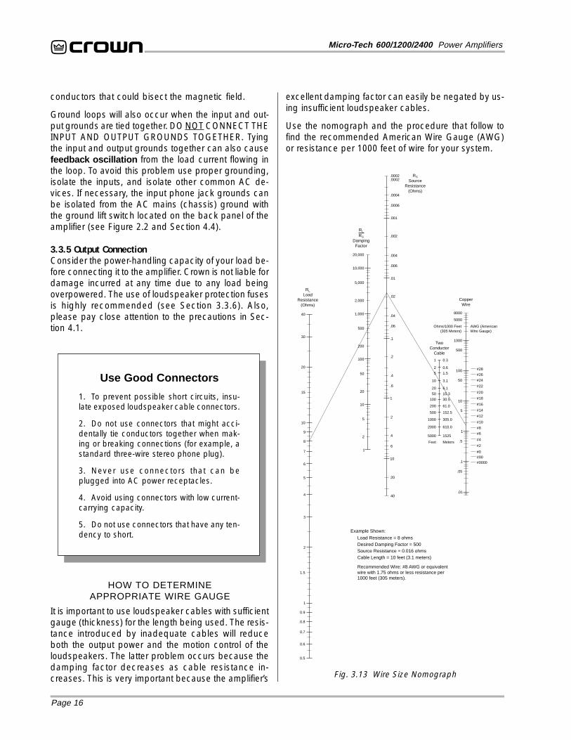
excellent damping factor can easily be negated by us-ing insufficient loudspeaker cables.
Use the nomograph and the procedure that follow tofind the recommended American Wire Gauge (AWG)or resistance per 1000 feet of wire for your system.
Use Good Connectors
1. To prevent possible short circuits, insu-late exposed loudspeaker cable connectors.
2. Do not use connectors that might acci-dentally tie conductors together when mak-ing or breaking connections (for example, astandard three-wire stereo phone plug).
3. Never use connectors that can beplugged into AC power receptacles.
4. Avoid using connectors with low current-carrying capacity.
5. Do not use connectors that have any ten-dency to short.
HOW TO DETERMINEAPPROPRIATE WIRE GAUGE
It is important to use loudspeaker cables with sufficientgauge (thickness) for the length being used. The resis-tance introduced by inadequate cables will reduceboth the output power and the motion control of theloudspeakers. The latter problem occurs because thedamping factor decreases as cable resistance in-creases. This is very important because the amplifier’s
Recommended Wire: #8 AWG or equivalentwire with 1.75 ohms or less resistance per1000 feet (305 meters).
1
0.5
200
500
1,000
2,000
20,000
5,000
10,000
.01
.001
.02
.004
.006
.002
.0004
.0006
.0002
0.3
1.5
0.6
3.1
6.1
15.3
30.5
61.0
152.5
305.0
610.0
1525
1
5
2
10
20
50
100
200
500
1000
2000
5000
.0002
0.6
0.7
0.8
1.5
0.9
Fig. 3.13 Wire Size Nomograph
Page 17
Micro-Tech 600/1200/2400 Power Amplifiers
1. Note the load resistance of the loudspeakers connectedto each channel of the amplifier. Mark this value on the“Load Resistance” line of the nomograph.
2. Select an acceptable damping factor and mark it on the“Damping Factor” line. Your amplifier can provide an excel-lent damping factor of 1,000 from 10 to 400 Hz in Stereomode with an 8 ohm load. In contrast, typical damping fac-tors are 50 or lower at these frequencies. Higher dampingfactors yield lower distortion and greater motion control overthe loudspeakers. A common damping factor for commer-cial applications is between 50 and 100. Higher dampingfactors may be desirable for live sound, but long cablelengths often limit the highest damping factor that can beachieved practically. (Under these circumstances, Crown’sIQ System is often used so amplifiers can be easily moni-tored and controlled when they are located very near theloudspeakers.) In recording studios and home hi-fi, a damp-ing factor of 500 or more is very desirable.
3. Draw a line through the two points with a pencil, and con-tinue until it intersects the “Source Resistance” line.
4. On the “Two Conductor Cable” line, mark the length ofthe cable run.
5. Draw a pencil line from the mark on the “Source Resis-tance” line through the mark on the “Two Conductor Cable”line and intersect the “Copper Wire” line.
6. The required wire gauge for the selected wire length anddamping factor is the value on the right-hand scale of the“Copper Wire” line. For metric wire sizes, find the recom-mended resistance in ohms per 305 meters (1000 feet) anduse this information to reference the correct wire size. Note:Wire size increases as the AWG gets smaller.
7. If the size of the cable exceeds what you want to use,(1) find a way to use shorter cables, like using the IQ Sys-tem, (2) settle for a lower damping factor, or (3) use morethan one cable for each line. Options 1 and 2 will require thesubstitution of new values for cable length or damping factorin the nomograph. For option 3, doubling the number ofconductors of equal thickness will reduce the resistance inohms per 1000 feet (305 meters) by half. When using AWGstandards, you can estimate the effective wire gauge bysubtracting 3 from the given wire gauge every time the num-ber of conductors of equal gauge is doubled. So, if #10 wireis too large, two #13 wires can be substituted, or four #16wires can be used for the same effect.
SOLVING OUTPUT PROBLEMSHigh-frequency oscillations can cause your ampli-fier to prematurely activate its protection circuitry. Theeffects of this problem are similar to the effects of theRF problems described in Section 3.3.4. To preventhigh-frequency oscillations, follow these guidelines:
1. When using long cable runs, or when differentamplifiers share a common cable tray or jacket,use tie-wraps to bundle individual conductors
so the wires for each loudspeaker are keptclose together. Do not bundle wires from differ-ent amplifiers. This reduces the chance of con-ductors acting like antennas that transmit orreceive the high frequencies that can cause os-cillations.
2. Avoid using shielded loudspeaker cable.
3. Never tie together input and output grounds.
4. Never tie together different amplifier outputs.
5. Keep output cables separated from inputcables.
6. Install an RF filter in series with each input (seeSection 3.3.4).
7. Install input wiring according to the instructionsin Section 3.3.4.
Another problem to avoid is the presence of large sub-sonic currents when primarily inductive loads areused. Examples of inductive loads are 70-volt step-uptransformers and electrostatic loudspeakers.
Inductive loads can act like a short circuit at low fre-quencies. This can cause the amplifier to producelarge low-frequency currents and activate its protec-tion circuitry. Always take the precaution of installing asubsonic filter in series with each of the amplifier’s in-puts when inductive loads are used. A three-pole, 18dB per octave filter with a –3 dB frequency of 50 Hz isrecommended (some applications may benefit from aneven higher –3 dB frequency). See Section 3.3.4 forsome examples.
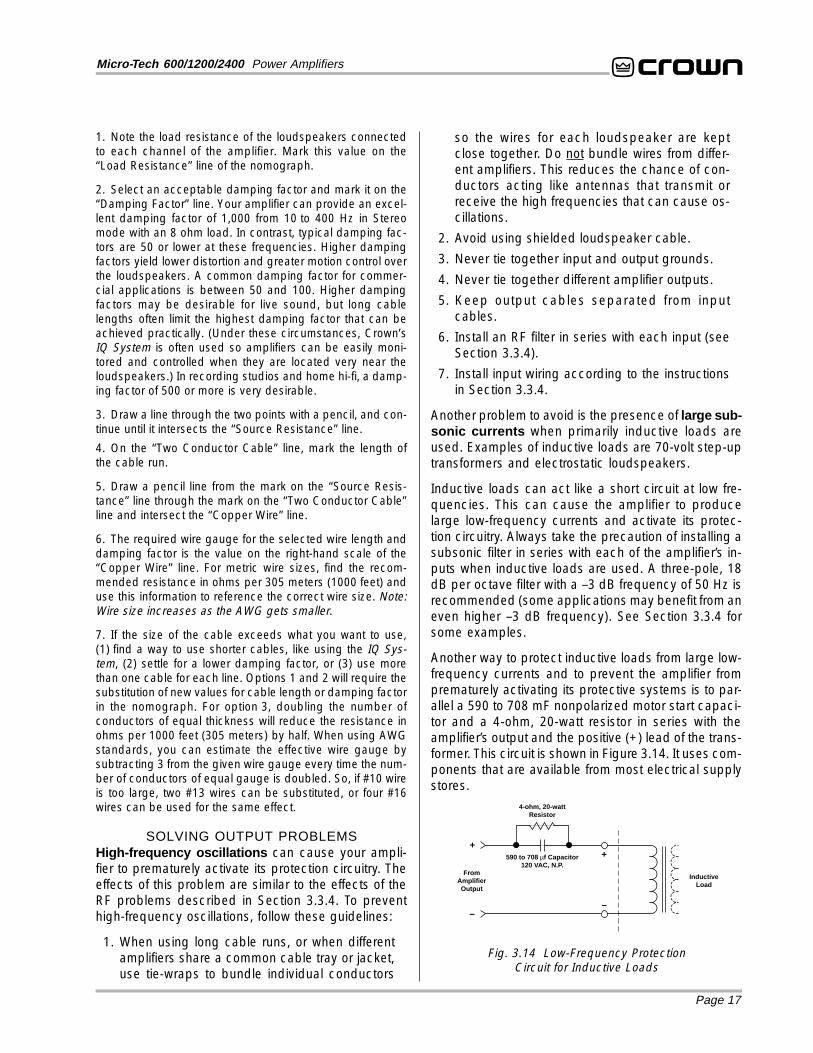
Another way to protect inductive loads from large low-frequency currents and to prevent the amplifier fromprematurely activating its protective systems is to par-allel a 590 to 708 mF nonpolarized motor start capaci-tor and a 4-ohm, 20-watt resistor in series with theamplifier’s output and the positive (+) lead of the trans-former. This circuit is shown in Figure 3.14. It uses com-ponents that are available from most electrical supplystores.
4-ohm, 20-wattResistor
590 to 708 µf Capacitor120 VAC, N.P.
+
–
InductiveLoad
+
–
FromAmplifierOutput
Fig. 3.14 Low-Frequency ProtectionCircuit for Inductive Loads
Page 18
Micro-Tech 600/1200/2400 Power Amplifiers
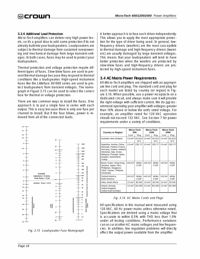
A better approach is to fuse each driver independently.This allows you to apply the most appropriate protec-tion for the type of driver being used. In general, low-frequency drivers (woofers) are the most susceptibleto thermal damage and high-frequency drivers (tweet-ers) are usually damaged by large transient voltages.This means that your loudspeakers will tend to havebetter protection when the woofers are protected byslow-blow fuses and high-frequency drivers are pro-tected by high-speed instrument fuses.
3.4 AC Mains Power RequirementsAll Micro-Tech amplifiers are shipped with an appropri-ate line cord and plug. The standard cord and plug foreach model are listed by country (or region) in Fig-ure 3.16. When possible, use a power receptacle on adedicated circuit, and always make sure it will providethe right voltage with sufficient current. We do not rec-ommend operating your amplifier with voltages greaterthan 10% above or below the unit’s rated voltage. Forexample, an amplifier rated for 120 VAC operatonshould not exceed 132 VAC. See Section 7 for powerrequirements under a variety of conditions.
3.3.6 Additional Load ProtectionMicro-Tech amplifiers can deliver very high power lev-els, so it’s a good idea to add some protection if its notalready built into your loudspeakers. Loudpseakers aresubject to thermal damage from sustained overpower-ing and mechanical damage from large transient volt-ages. In both cases, fuses may be used to protect yourloudspeakers.
Thermal protection and voltage protection require dif-ferent types of fuses. Slow-blow fuses are used to pre-vent thermal damage because they respond to thermalconditions like a loudspeaker. High-speed instrumentfuses like the Littlefuse 361000 series are used to pro-tect loudspeakers from transient voltages. The nomo-graph in Figure 3.15 can be used to select the correctfuse for thermal or voltage protection.
There are two common ways to install the fuses. Oneapproach is to put a single fuse in series with eachoutput. This is easy because there is only one fuse perchannel to install. But if the fuse blows, power is re-moved from all of the connected loads.
All specifications in this manual were measured using120 VAC, 60 Hz power mains unless otherwise noted.Specifications are derived using a mains voltage thatis accurate to within 0.5% with THD less than 1.0%under all testing conditions. Performance variationscan occur at other AC mains voltages and line frequen-cies. In addition, line regulation problems will directlyaffect the output power available from the amplifier.Fig. 3.15 Loudspeaker Fuse Nomograph
Fig. 3.16 AC Mains Cords and Plugs
Country or RegionMicro-Tech
600Cord Plug Cord Plug
Australia, New Zealand
Brazil, Guam, Hong Kong,Jamaica, Japan, Peru,Phillipines, Singapore,Tahiti, Taiwan, Thailand,Venezuela
NEMA5-15P
14/3 SJT NEMA5-15P
12/3 SO NEMA5-15P
1.5 mm2 AS 311210 A
14/3 SJT
BS 546
BS 1363
1.5 mm2
1.5 mm2
BS 546
BS 1363
1.5 mm2
1.5 mm2
BS 546
BS 1363
1.5 mm2
1.5 mm2
Central America,North America
NEMA5-15P
14/3 SJT NEMA5-15P
12/3 SO NEMA5-20P
14/3 SJT
India, South Africa
Ireland, Norway,United Kingdom,United Arab Emirates
4 Operation4.1 PrecautionsAlthough your amplifier is protected from internal andexternal faults, you should still take the following pre-cautions for optimum perfromance and safety:
1. Improper wiring for the Stereo, Bridge-Mono andParallel-Mono modes can result in serious operat-ing difficulties (see Section 3.3).
2. WARNING: Do not change the position of thestereo/mono switch unless the amplifier is fir stturned off.
3. CAUTION: In Parallel-Mono mode, a jumper isused between the red (+) channel 1 and 2 redoutput binding posts. Remove this jumper forBridge-Mono and Stereo modes, or high distor-tion and excessive heating will occur. Also,check the stereo/mono switch for proper setting.
4. Turn off the amplifier and unplug it fr om the A Cmains before removing the back panel cover plateor before removing and cleaning the dust filter.
5. Use care when making connections, selecting sig-nal sources and controlling the output level. Theload you save may be your own!
6. Do not short the ground lead of an output cable tothe input signal ground. This will form a ground loopand may cause oscillations.
7. Operate the amplifier from AC mains of not morethan 10% above or below the selected line voltageand only at the specified line frequency.
8. Never connect the output to a power supply out-put, battery or power main. Such connectionsmay result in electrical shock.
9. Tampering with the circuitry by unqualified person-nel or making unauthorized circuit changes may behazardous and invalidates all agency listings.
Remember: Crown is not liable for damage that resultsfrom overdriving other system components.
4.2 IndicatorsThe amber enable indicator is provided to show thatthe amplifier has been turned on (or enabled), and itslow-voltage power supply and forced-air cooling sys-tem are working. It does not indicate the status of thehigh-voltage power supplies. For example, the enableindicator will remain lit during unusual conditions thatwould cause the amplifier’s protection systems to tem-
porarily remove power from a high-voltage power sup-ply (see Section 4.3).
The amber ODEP indicators confirm the normal op-eration of Crown’s patented Output Device EmulationProtection circuitry. During normal operation, they glowbrightly to show the presence of reserve thermody-namic energy. They dim proportionally as the energyreserve decreases. In the rare event that there is noreserve, the indicators turn off and ODEP proportion-ally limits the drive level of the output stages so theamplifier can continue safe operation even when con-ditions are severe. (For a more detailed description ofODEP, see Section 4.3.1.)
The ODEP indicators also turn off if the amplifier losesAC power, the power switch is turned off, or the low-voltage power supply fuse blows. The ODEP indicatorfor the affected channel will turn off if a high-voltagepower supply fuse or breaker blows, or if the channelactivates transformer thermal protection. Conditionsthat activate “drive protection” do not affect the ODEPindicators (see Section 4.3.3).
4.3 Protection SystemsMicro-Tech amplifiers have extensive protection sys-tems including ODEP, ultrasonic/RF protection, driveprotection, and power supply fuses or breakers.
4.3.1 ODEPCrown invented ODEP to solve two long-standing prob-lems in amplifier design: to prevent amplifier shutdownduring demanding operation, and to increase the effi-ciency of the output circuitry.
To do this, Crown established a rigorous program tomeasure the safe operating area (SOA) of each outputtransistor before installing it in an amplifier. Next, Crowndesigned intelligent circuitry to simulate the instanta-neous operating conditions of those output transistors.Its name describes what it does: Output Device Emu-lation Protection or ODEP. In addition to simulating out-put transistor operating conditions, it compares theiroperation to their known SOA. If ODEP sees that more
ODEP
CH1 CH2
POWER
OFF
Fig. 4.1 Indicators
Page 20
Micro-Tech 600/1200/2400 Power Amplifiers
4.3.4 Transformer Thermal ProtectionAll Micro-Tech amplifiers have transformer thermal pro-tection. The amplifier’s transformer thermal protectioncircuitry is activated in very unusual circumstanceswhere the unit’s transformer temperature rises to un-safe levels. Under these abnormal conditions, the am-plifier will remove power from the affected channel’shigh-voltage power supply which puts the channel indrive protection mode. The amplifier channel will re-turn to normal operation after its transformer cools to asafe temperature.
It is extremely unlikely that you will ever see aMicro-Tech amplifier activate transformer thermal pro-tection as long as it is operated within rated conditions(see Section 6). One reason is that ODEP keeps theamplifier working under very severe conditions. Evenso, higher than rated output levels, excessively low-impedance loads and unreasonably high input signalscan generate more heat in the transformer than in theoutput devices. These conditions can overheat a trans-former and activate its protection system.
Micro-Tech amplifiers are designed to keep workingunder conditions where other amplifiers would fail. Buteven when a Micro-Tech’s limits are exceeded, it willstill protect itself—and your investment—from damage.
4.3.5 Fuses and Circuit Breakers120 VAC, 60 Hz models and all Micro-Tech 2400s havean internal fuse that protects the low-voltage supplyand cooling fan. Micro-Tech 600 and 1200 high-volt-age supplies are protected by internal fuses, while Mi-cro-Tech 2400 high-voltage supplies are protected bycircuit breakers. With rated loads and output levels,the fuses (or circuit breakers) should only shut downthe amplifier in the rare instance of a catastrophic fail-ure. ODEP protection keeps the amplifier operationalunder most other severe conditions. The fuses (or cir-cuit breakers) can also shut down the amplifier in caseswhere extremely low-impedance loads and high out-put levels result in current draw that exceeds their rat-ing. Again, this should only be possible when operatingoutside rated conditions like when the amplifier is usedto drive a 1 ohm load in Stereo mode, or when an inputsignal is clipped severely.
Micro-Tech amplifiers do not blow their fuses or triptheir breakers unless something is wrong. In the rareevent that an internal fuse blows, please refer the unitto a qualified technician. If a breaker in a Micro-Tech2400 trips, try to identify and correct the problem be-fore resetting the breakers. If the problem persists, re-fer the unit to a qualified technician.
power is needed from the output devices than theycan deliver under the present conditions, ODEP imme-diately limits the drive level until it falls within the SOA.Limiting is proportional and kept to an absolute mini-mum—only what is required to prevent damage. Un-der normal conditions, no limiting is required and ODEPis transparent to the audio signal.
This level of protection enables Crown to increase out-put efficiency to never-before-achieved levels whilegreatly increasing reliability. As described previously,ODEP operation is monitored by the front panel ODEPindicators. They show whether the amplifier is function-ing correctly or if ODEP is limiting the drive level.
With ODEP you get maximum power with maximumprotection so the show goes on.
4.3.2 Ultrasonic and Radio Frequency ProtectionMicro-Tech amplifiers have a controlled slew rate. Thismeans that their design limits the frequencies they canreproduce. At the same time, the amplifier’s controlledslew rate has no effect on its audio performance be-cause limiting occurs well above 20 kHz. This ap-proach protects the amplifier from radio frequencies,and also protects some sensitive loads (like tweeters).In the real world, an amplifier’s slew rate only needs tobe large enough to deliver the maximum voltage at thehighest required frequency—higher slew rates actu-ally allow the reproduction of undesirable frequencies.
4.3.3 Drive ProtectionThe drive protection system temporarily removes drivefrom the output stages to protect the amplifier and itsload(s). Drive protection can be activated in two situa-tions. First, if dangerous subsonic frequencies or di-rect current (DC) is detected in the amplifier’s output,the unit will activate its DC/low-frequency protectioncircuitry which puts the affected channel in drive pro-tection mode. This protects the load(s) and preventsoscillation. The amplifier resumes normal operationwhen it no longer detects dangerous output. Althoughit is extremely unlikely that you will ever activate theamplifier’s DC/low-frequency protection system, im-proper source materials like subsonic square waves ora severely clipped signal can activate this system.
The amplifier’s fault protection system puts the affectedchannel into drive protection mode in rare situationswhere heavy common-mode current is detected in itsoutput. The amplifier should never output heavy com-mon-mode current unless its circuitry is damaged.Activating drive protection helps prevent further dam-age.
Page 21
Micro-Tech 600/1200/2400 Power Amplifiers
4.4 ControlsThe power switch is located on the front panel so youcan easily turn the amplifier on or off. If you ever needto make any wiring or installation changes, don’t forgetto disconnect the power cord. Please follow thesesteps when first turning on your amplifier:
1. Turn down the level of your audio source. Forexample, set your mixer’s volume to “∞” (off).
2. Turn down the amplifier’s level controls locatedon the back panel.
3. Turn on the power switch. The enable indicatorbeside the switch should glow.
4. After the turn-on delay, turn up the level of youraudio source to the maximum desired level.
5. Turn up the level controls on the back panel ofthe amplifier until the maximum desired loud-ness or power level is achieved.
6. Turn down the level of your audio source to itsnormal range.
You can adjust each channel’s output using the backpanel level controls . These controls are located onthe back panel to help prevent unwanted tampering.
A three-position input sensitivity switch is located in-side the amplifier’s back panel cover plate. The switchis set at the factory to a sensitivity of 0.775 volts forstandard 1 kHz power into 8 ohms. If desired, the sen-sitivity can be switched to 1.4 volts for standard 1 kHzpower into 8 ohms, or a voltage gain of 26 dB. The 26dB gain setting is equivalent to a sensitivity of 2.1 voltsfor the Micro-Tech 600, 2.5 volts for the Micro-Tech1200 and 3.2 volts for the Micro-Tech 2400.
To change the input sensitivity:
1. Turn off the amplifier and disconnect its powercord from the AC power source.
2. Remove the back panel cover plate (or inputconnector accessory).
3. Locate the access hole for the sensitivity switchinside the chassis opening (Figure 4.2). Thesensitivity switch will not be visible because it ismounted below the hole. Use your little finger toreach it.
4. Set the switch to the desired position noted onthe label beside the access hole.
5. Replace the back panel cover plate (or inputconnector accessory) and restore power.
The back panel stereo/mono switch is used to selectStereo, Bridge-Mono or Parallel-Mono operating mode.Power must be removed from the amplifier before se-lecting a different operating mode. There are also im-portant wiring differences among the different modes,so be sure to read Section 3.3 before changing theposition of the stereo/mono switch.
The ground lift switch is located on the back paneland can isolate the input signal grounds from the AC(chassis) ground. It affects only the phone jack inputsand has no affect on accessory input connectors. Slid-ing the switch to the left isolates or “lifts” the groundsby placing an impedance between the sleeve of eachphone jack and the AC ground.
The Micro-Tech 2400 has two reset switches for itshigh-voltage power supplies. Refer to Section 4.3.5 inthe unusual event of a tripped breaker.
4.5 Filter CleaningA dust filter is provided on the air intake to the coolingsystem (Figure 2.1). If this filter becomes clogged, theunit will not cool as efficiently as it should and may pro-duce lower-than-normal output levels due to high heatsink temperature.
To remove the filter, use a phillips screwdriver to re-move the three screws that hold the front grille in place.Wash the filter with mild dishwashing detergent andwarm water. Be sure to dry the filter before reinstallingit. Replacement filters may be ordered from the fac-tory.
Dust filters are not 100% efficient—depending on thelocal environment, the internal heat sinks of the ampli-fier will benefit from periodic cleaning by a qualifiedtechnician. Internal cleaning information is availablefrom our Technical Support Group.Fig. 4.2 Input Sensitivity and Ground Lift Switches
0.77 V26 dB
SENSITIVITY SWITCH INSIDE ACCESS HOLE
1.4 V
UNBALANCEDINPUT WIRING
BALANCEDINPUT WIRING
+–
TIP
RING
SLEEVEGND
+ TIP
SLEEVEGND
THIS AMPLIFIER IS EQUIPPED WITH SELECTABLE INPUT SENSITIVITY. REMOVE COVER PLATE (ABOVE) TO ACCESS SENSITIVITY SWITCH.
CH-2
INPUT GROUND LIFT
(AFFECTS PHONE INPUTS ONLY.) (MONO)INPUTGAIN
CH-1
INPUT GAINLIFT 0
1
2
3
45 6 7
89
10
11120
1
2
3
45 6 7
89
10
1112
GROUND LIFT SWITCH
Page 22
Micro-Tech 600/1200/2400 Power Amplifiers
5 Technical Information5.1 OverviewMicro-Tech amplifiers incorporate several technologi-cal advancements including real-time computer simu-lation of output transistor stress, low-stress outputstages and an advanced heat sink embodiment.
Custom circuitry is incorporated to limit temperatureand current to safe levels making it highly reliable andtolerant of faults. Unlike many lesser amplifiers, it canoperate at its voltage and current limits without self-destructing.
Micro-Tech amplifiers are protected from all commonhazards that plague high-power amplifiers includingshorted, open or mismatched loads; overloaded powersupplies; excessive temperature, chain-destructionphenomenon, input overload and high-frequency blow-ups. The unit protects loudspeakers from input andoutput DC, as well as turn-on and turn-off transients.
Real-time computer simulation is used to create ananalogue of the junction temperature of the output de-vices (output transistors). Current is limited only whenthe device temperature becomes excessive—and onlyby the minimum amount required). This patented ap-proach called Output Device Emulation Protection (orODEP) maximizes the available output power and pro-tects against overheating—the major cause of devicefailure.
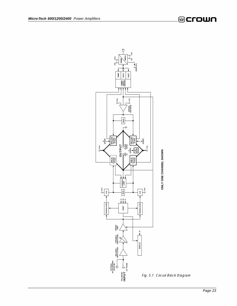
Crown also invented the four-quadrant topology usedin the output stages of each Micro-Tech amplifier (seeFigure 5.1). This special circuitry is called the groundedbridge. It makes full use of the power supply by deliv-ering peak-to-peak voltages to the load that are twicethe voltage seen by the output devices.
As its name suggests, the grounded bridge topologyis referenced to ground. Composite devices are con-structed as gigantic NPN and PNP devices to handlecurrents which exceed the limits of available devices.Each output stage has two composite NPN devicesand two composite PNP devices.
The devices connected to the load are referred to as“high-side NPN and PNP” and the devices connectedto ground are referred to as “low-side NPN and PNP.”Positive current is delivered to the load by increasingconductance simultaneously in the high-side NPN andlow-side PNP stage, while decreasing conductance ofthe high-side PNP and low-side NPN.
The two channels may be used together to double thevoltage (Bridge-Mono) or current (Parallel-Mono) pre-
sented to the load. This feature gives you flexibility tomaximize power available to the load.
A wide bandwidth, multiloop design is used for state-of-the-art compensation. This produces ideal behaviorand results in ultra-low distortion values.
Aluminum extrusions have been widely used for heatsinks in power amplifiers due to their low cost and rea-sonable performance. But measured on a watts perpound or watts per volume basis, the extrusion tech-nology doesn’t perform nearly as well as the heat sinktechnology developed for Micro-Tech amplifiers.
The heat sinks in a Micro-Tech amplifier are fabricatedfrom custom convoluted fin stock that provides an ex-tremely high ratio of area to volume, or area to weight.All power devices are mounted directly to massive heatspreaders that are electrically at the Vcc potential.Making the heat spreaders electrically alive improvesthermal performance by eliminating the insulating in-terface underneath each power device. The chassisitself is also used as part of the thermal circuit to maxi-mize utilization of the available resources.
5.2 Circuit TheoryEach channel is powered by its own power transformerT100 or T200. Both channels share a common low-voltage supply. The secondary output of T100 is full-wave rectified by D109 and is filtered by a largecomputer grade capacitor. A thermal switch embed-ded in the transformer protects it from overheating.
The low-voltage fanformer is rectified by diodes D1,D2, D3 and D4 to generate an unregulated 24 volts.Monolithic regulators U1 and U2 provide a regulated±15 volts.
5.2.1 Stereo OperationFor simplicity, the discussion of Stereo operation willrefer to one channel only. Mono operation will be dis-cussed later. For specific circuit references, see theblock diagram in Figure 5.1 and the schematics pro-vided at the back of this manual.
The signal at the ¼-inch phone jack input passes di-rectly to the balanced gain stage (U104-A andU104-B). The balanced gain stage causes balancedto single-ended conversion using a difference ampli-fier. From there, gain can be controlled with a potenti-ometer. The error amp (U104-C) amplifies thedifference between the output signal and the input sig-nal from the gain pot, and drives the voltage translatorstage.
Page 23
Micro-Tech 600/1200/2400 Power Amplifiers
FAUL
T
ON
LY
ON
E C
HA
NN
EL
SH
OW
N
NP
N H
IO
UT
PU
TS
TA
GE
NP
N L
OW
OU
TP
UT
ST
AG
E
PN
P L
OW
OU
TP
UT
ST
AG
E
PN
P H
IO
UT
PU
TS
TA
GE
RE
D(+
)B
LA
CK
(GN
D)
OU
TP
UT
+Vcc
–Vcc
TR
AN
SL
AT
OR
LVA
LVA+V
cc
–Vcc
BIA
SC
UR
RE
NT
LIM
IT
TR
AN
SL
AT
OR
BA
LA
NC
EIN
PU
T S
TA
GE
BA
LA
NC
ED
INP
UT
VA
RIA
BL
EG
AIN
ST
AG
EE
RR
OR
AM
P
DIS
PL
AY
BIA
S
BR
IDG
EB
AL
AN
CE
+Vcc
–Vcc
POW
ERSU
PPLY
CON
TRO
LDC
/LF
TIM
ER
POW
ER+Vcc
–Vcc
OD
EP
A B
A(O
DE
P)
B(O
DE
P)
SUPP
LY
D
C
HS
TE
MP
C(O
DE
P)
+24
–24
1/4"
PH
ON
E
OP
TIO
NA
LM
T-X
LR
(S
HO
WN
)O
R M
T-B
B
D(D
ISP
LA
Y)
Fig. 5.1 Circuit Block Diagram
Page 24
Micro-Tech 600/1200/2400 Power Amplifiers
From the error amp, the voltage translator stage routesthe signal to the Last Voltage Amplifiers (LVAs) basedon signal polarity. The +LVA (Q105) and the –LVA(Q110), with their push-pull effect through the bias servoQ318, drive the fully complementary output stage.
The bias servo Q318 is thermally coupled to the heatsink and sets the quiescent bias current in the outputstage to lower the distortion in the crossover region ofthe output signal. D301, D302, D303, and D304 re-move the charge on the unused portion of the outputstage based on the polarity of the output signal.
With the voltage swing provided by the LVAs, the sig-nal then gains current amplification through theDarlington emitter-follower output stage.
The bridge-balanced circuit (U104-D) receives a sig-nal from the output of the amplifier and compares it tothe signal at the Vcc supply. The bridge-balanced cir-cuit then develops a voltage to drive the bridge-bal-anced output stage. This results in the Vcc supplyhaving exactly one half of the output voltage added totheir quiescent voltage. D309, D310, D311 and a trim-mer resistor set the quiescent current point for thebridge-balanced output stage.
The protection mechanisms that affect the signal pathare implemented to protect the amplifier under real-world conditions. These conditions are high instanta-neous current, excessive temperature, and outputdevice operation outside safe conditions.
Q107 and Q108 sense output current and act as acommon current limiter. When instantaneous currentexceeds the design criteria, the limiters remove the drivefrom the LVAs to limit output current to safe levels.
To further protect the output stages, the patented ODEPcircuitry produces an analog output proportional to thealways changing die temperature of the output transis-tor. This output controls the translator stage previouslymentioned, removing any further drive that may exceedthe safe operating area of the output stage.
Thermal sensors S100 and S200 give the ODEP cir-
cuits vital information on the operating temperature ofthe heat sink on which the output devices are mounted.
Should the amplifier fail in a way that would cause DCacross the output lead, the DC protection circuit sensesthis on the negative feedback loop and shuts down theoutput stage drive until the DC is removed.
5.2.2 Bridge-Mono OperationBy setting the back panel stereo/mono switch to Bridge-Mono, you can convert a Micro-Tech amplifier forbridged-mono operation. With a signal applied to thechannel 1 input and the load connected between thepositive (+) output terminals, twice the voltage can bedelivered to the load.
The channel 1 output feeds the channel 2 error ampU204-A. The signal feeding channel 2 is inverted sothe channel 2 output will have the opposite polarity ofchannel 1. This makes it possible to deliver twice asmuch voltage to the load while the protection mecha-nisms for each channel continue to work independently.
5.2.3 Parallel-Mono OperationWith the stereo/mono switch set to Parallel-Mono, theoutput of channel 2 is paralleled with that of channel 1.A suitable jumper capable of handling high current mustbe connected across the positive (+) output terminalsto gain the benefits of this operating mode.
The signal path for channel 1 is the same as previouslydiscussed, except that channel 1 also drives the out-put stage of channel 2. The balanced input, error amp,translators, and LVAs of channel 2 are disconnectedand no longer control the channel 2 output stage. Thechannel 2 output stage and protection mechanismsare also coupled through S1 and function as one.
In Parallel-Mono mode, the amplifier can deliver twicethe current of a single channel. Because the channel 2ODEP circuit is coupled through S1, the amplifier gainsadditional protection if a fault occurs in the channel 2output stage. The channel 2 ODEP circuit will limit theoutput of both output stages by removing the drive fromthe channel 1 voltage translator.
Page 25
Micro-Tech 600/1200/2400 Power Amplifiers
6 SpecificationsThe following applies to units in Stereo mode with with both channelsdriven into 8 ohm loads and an input sensitivity of 26 dB unless other-wise specified.
Standard 1 kHz Power: refers to maximum average power in watts at1 kHz with 0.1% THD+noise.
Full Bandwidth Power: refers to maximum average power in wattsfrom 20 Hz to 20 kHz with 0.1% THD+noise.
120 VAC, 60 Hz Units: refers to amplifiers with dedicated transform-ers for 120 VAC, 60 Hz power mains.
International Units: refers to amplifiers with special multi-tap trans-formers that can be configured for several AC mains voltages (somemay be labeled 601, 1201 or 2401).
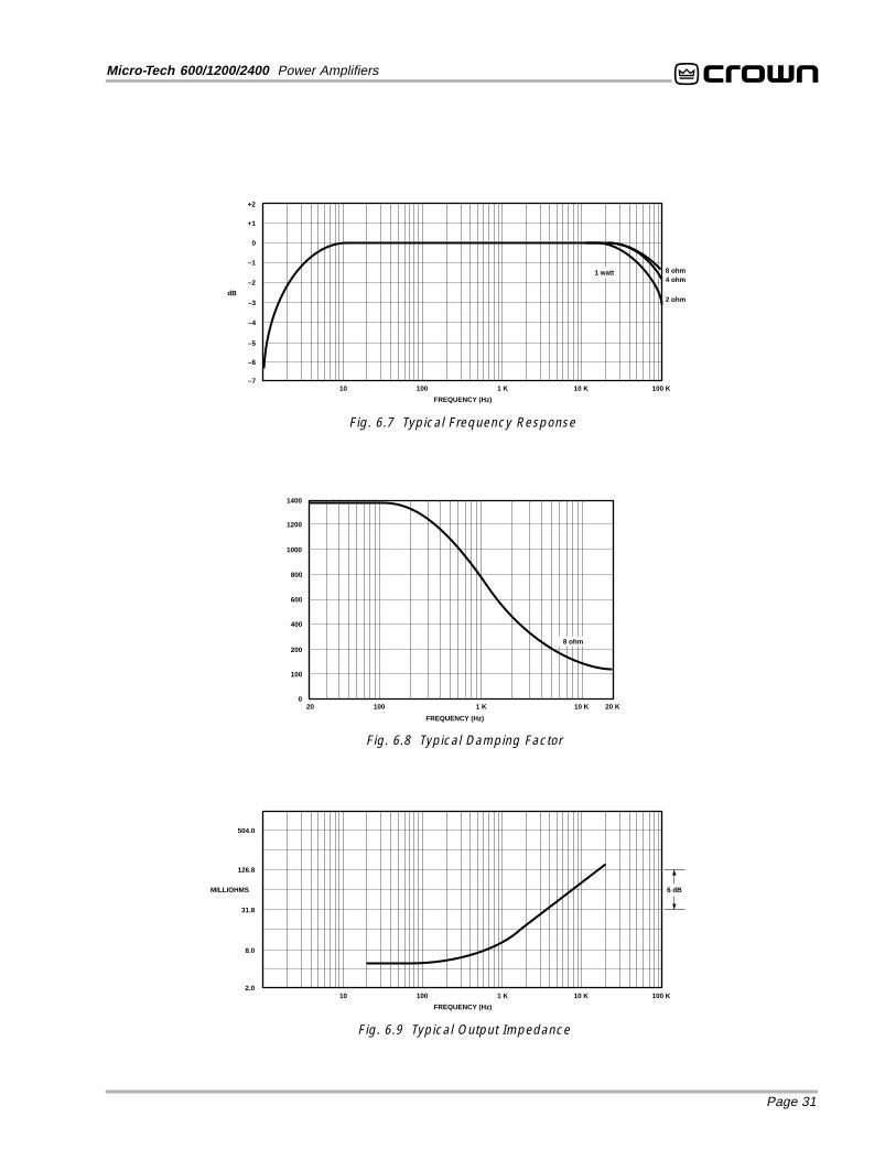
PerformanceFrequency Response: ±0.1 dB from 20 Hz to 20 kHz at1 watt (see Figure 6.7).
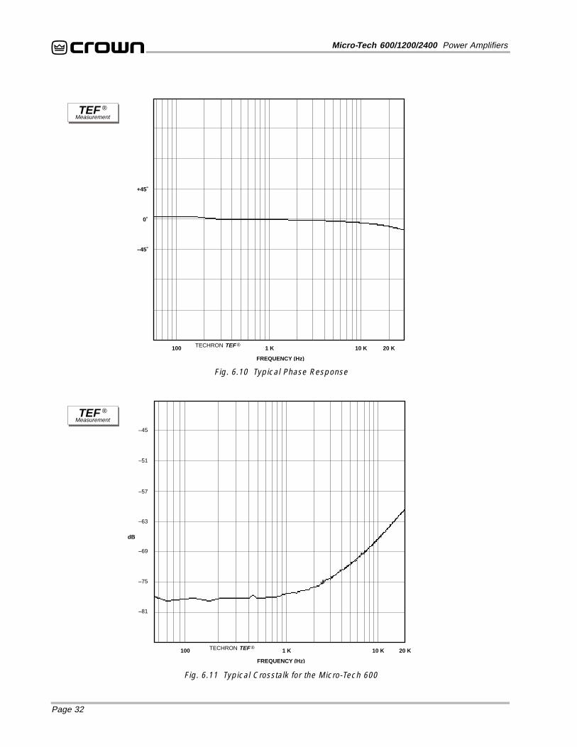
Phase Response: ±10 degrees from 10 Hz to 20 kHz at1 watt (see Figure 6.10).
Signal-to-Noise: A-weighted, better than 105 dB belowfull bandwidth power. From 20 Hz to 20 kHz, better than100 dB below full bandwidth power.
Total Harmonic Distortion (THD): Less than 0.05% at fullbandwidth power from 20 Hz to 1 kHz increasing linearly to0.1% at 20 kHz.
Intermodulation Distortion (IMD): (60 Hz and 7 kHz 4:1)Less than 0.05% from 163 milliwatts to full bandwidthpower.
Damping Factor: Greater than 1,000 from 10 Hz to 400 Hz(see Figure 6.8).
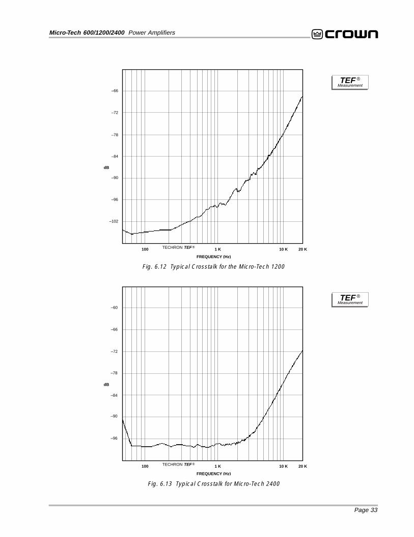
Crosstalk: See Figures 6.11, 6.12 and 6.13.
Controlled Slew Rate: Greater than 13 volts /ms.
Common Mode Rejection (CMR): At rated full bandwidthpower, better than 70 dB from 20 Hz to 1 kHz falling linearlyto better than 50 dB at 20 kHz.
Voltage Gain: 20: 1 ±3% or 26 dB ±0.25 dB at the maxi-mum level setting (also see Section 4.4).
Micro-Tech 600: 55:1 ±12% or 35 dB ±1 dB at 0.775 voltsensitivity; 31:1 ±12% or 30 dB ±1 dB at 1.4 volt sensitivity.
Micro-Tech 1200: 64:1 ±12% or 36 dB ±1 dB at 0.775 voltsensitivity; 34:1 ±12% or 31 dB ±1 dB at 1.4 volt sensitivity.
Micro-Tech 2400: 83:1 ±12% or 38 dB ±1 dB at 0.775 voltsensitivity; 46:1 ±12% or 33 dB ±1 dB at 1.4 volt sensitivity.
PowerOutput Power: The following are guaranteed minimumsfor standard 1 kHz power from 120 VAC, 60 Hz North Ameri-can units. For more information or specifications on inter-national units, see the power matrices that follow.
Micro-Tech 600Stereo mode (both channels driven):
400 watts into 2 ohms.325 watts into 4 ohms.220 watts into 8 ohms.
Bridge-Mono mode:750 watts into 4 ohms.655 watts into 8 ohms.450 watts into 16 ohms.
Parallel-Mono mode:700 watts into 1 ohm.665 watts into 2 ohms.450 watts into 4 ohms.
1,050 watts into 2 ohms.800 watts into 4 ohms.520 watts into 8 ohms.
Bridge-Mono mode:2,070 watts into 4 ohms.1,585 watts into 8 ohms.1,035 watts into 16 ohms.
Parallel-Mono mode:2,080 watts into 1 ohm.1,605 watts into 2 ohms.1,035 watts into 4 ohms.
Load Impedance: Safe with all types of loads. Rated for 2to 16 ohms in Stereo, 4 to 16 ohms in Bridge-Mono and 1to 4 ohms in Parallel-Mono mode.
Required AC Mains: 100, 120, 220 and 240 VAC (±10%),50 and 60 Hz units are available. All units draw 90 watts orless when idle. AC mains current, frequency and voltagerequirements are provided on the unit’s back panel (alsosee Section 7).
Important: Your amplifier must have sufficient AC power.Amplifiers cannot create energy—they require proper volt-age and current to deliver the power you expect.
Page 26
Micro-Tech 600/1200/2400 Power Amplifiers
ControlsPower: A front panel rocker switch used to turn the ampli-fier on and off.
Level: A back panel rotary potentiometer for each chan-nel used to control the output level.
Stereo/Mono: A three-position back panel switch used toselect Stereo, Bridge-Mono or Parallel-Mono mode.
Sensitivity: A three-position switch inside the back coverplate used to select the input sensitivity for both channels:0.775 volts or 1.4 volts for standard 1 kHz power into8 ohms, or 26 dB gain (see Section 4.4).
Ground Lift: A two-position back panel switch used toisolate the phone jack input grounds from the AC ground.
Reset (Micro-Tech 2400 only): A back panel push buttonfor each channel used to reset the circuit breaker for eachchannel.
IndicatorsEnable: This amber indicator shows the on/off status ofthe low-voltage power supply and cooling fan.
ODEP: These amber indicators show the thermodynamicenergy reserve for each channel. Normally they are brightlyilluminated to show that reserve energy is available. In therare event there is no reserve, they will dim in proportion toODEP limiting. They remain off if the power is turned off,disconnected, or if the low-voltage power supply fuseblows. A channel’s ODEP indicator will also remain off if itshigh-voltage supply fuse blows (or breaker opens) or iftransformer thermal protection is activated.
Input/OutputInput Connector: Two balanced ¼-inch phone jacks. SeeSection 8.2 for XLR and barrier block accessories.
Input Impedance: Nominally 20 K ohms, balanced. Nomi-nally 10 K ohms, unbalanced.
Input Sensitivity: Settings include 0.775 volts and 1.4 voltsfor standard 1 kHz power, or 26 dB gain (see Section 4.4).
Output Connectors: Two sets of color-coded bindingposts for banana plugs, spade lugs or bare wire (Euro-pean models do not accept banana plugs).
Output Impedance: Less than 10 milliohms in series withless than 2 microhenries (see Figure 6.9).
DC Output Offset: (Shorted input) ±10 millivolts.
Output SignalStereo: Unbalanced, two-channel.
Bridge-Mono: Balanced, single-channel. Channel 1 con-trols are active; channel 2 should be turned down.
Parallel-Mono: Unbalanced, single-channel. Channel 1controls are active; channel 2 is bypassed.
ProtectionMicro-Tech amplifiers are protected against shorted, openor mismatched loads; overloaded power supplies; exces-sive temperature, chain destruction phenomena, input over-load damage and high-frequency blowups. They alsoprotect loudspeakers from input/output DC and turn-on/turn-off transients.
If unreasonable operating conditions occur, the patentedODEP circuitry will proportionally limit the drive level toprotect the output stages, particularly in the case of el-evated temperature. Transformer overheating will result ina temporary shutdown of the affected channel; when it hascooled to a safe temperature, the transformer will auto-matically reset itself. Controlled slew rate voltage amplifi-ers prevent RF burnouts, and input overload protection isprovided by the input current limit. Refer to Section 4.3.
Turn On: The four-second turn-on delay prevents danger-ous turn-on transients. Turn-on occurs at zero crossing ofthe AC waveform, so power sequencers are rarely neededwith multiple units. Note: To change the turn-on delay time,contact Crown’s Technical Support Group.
ConstructionSteel chassis with durable black finish, front panel Lexanoverlay and specially designed “flow-through” ventilationfrom front to side panels.
Dimensions: Standard 19 inch (48.3 cm) rack mount width(EIA RS-310-B), 3.5 inch (8.9 cm) height and 16 inch(40.6 cm) depth behind the mounting surface.
Approximate Weight: Center of gravity is 6 inches(15.2 cm) behind the front mounting surface.
120 VAC, 60 Hz Units:Micro-Tech 600: 36 pounds, 4 ounces (16.5 kg) net;41 pounds, 2 ounces (18.7 kg) shipping weight.
Micro-Tech 1200: 41 pounds, 1 ounce (18.6 kg) net;45 pounds, 3 ounces (20.5 kg) shipping weight.
Micro-Tech 2400: 46 pounds, 14 ounces (21.3 kg) net;55 pounds, 12 ounces (25.3 kg) shipping weight.
International Units:Micro-Tech 600: 39 pounds, 7 ounces (17.9 kg) net;44 pounds, 2 ounces (20.0 kg) shipping weight.
Micro-Tech 1200: 41 pounds, 0 ounces (18.6 kg) net;45 pounds, 4 ounces (20.5 kg) shipping weight.
Micro-Tech 2400: 47 pounds, 9 ounces (21.6 kg) net;56 pounds, 6 ounces (25.6 kg) shipping weight.
Page 27
Micro-Tech 600/1200/2400 Power Amplifiers
Crown specifications are guaranteed for three years.In an effort to provide you with as much information as possible about the high power-producing capabilities of your amplifier, we have createdthe following power matrices.
Minim um Power SpecificationsCrown’s minimum power specifications represent the absolute smallest amount of output power you can expect from your amplifier when it isdriven to full output under the given conditions. Some spaces in each matrix may be left blank because the same guarantee is not provided forthose conditions—however, your amplifier will perform well under all conditions listed in each matrix.
When measuring power, 0.1% THD appears to be the industry standard for distortion. Two of the maximum average power specifications shownin each minimum power matrix are measured at 0.1% THD+noise so you can easily compare Crown specifications to those of other manufactur-ers. But this high level of distortion actually allows for some clipping which is undesirable. Because of this, a maximum average power specifica-tion at 0.05% THD+noise is included in each minimum power matrix which represents non-clipped conditions. Although most manufacturers donot give you power specifications at 0.05% THD, we encourage them to provide these specifications so you will have a more realistic represen-tation of the way amplifiers should be used in the real world—without a clipped output signal.
Many manufacturers publish power specs with a tolerance of ±1 dB or worse. This means their amplifier can deviate more than 20% in output! A100 watt amplifier would meet their specification if it only produced 79.4 watts. Other manufacturers qualify their specifications by saying theyare “typical,” “subject to manufacturing tolerances,” “single channel driven” or that they are specified with “fuses bypassed.” Each of thesestatements effectively removes any performance guarantee. In fact, some manufacturers use these tactics to generate large power numbers,and they don’t even print a disclaimer. We take a different approach at Crown—our amplifiers are guaranteed to meet or exceed their specifica-tions for three years. Further, because our published specs are set below our “in-house” measurements, you can expect every Crown amplifierto exceed its published minimum power specs. We believe you should get what you pay for.
8
2
Micro-Tech 600 – Minimum Guaranteed Power (Watts)
Stereo/MonoMode
Stereo(both channels
driven)
Bridge-Mono(balanced output)
Parallel-Mono
1
16
4
4
FTC Continuous Average0.1% THD + Noise
(See note 4)
1 kHz 20Hz-20kHz
285
210
570
420
320
220
645
450
635
450
Maximum Average
Load
(Ohm
s)
AC M
ains
120
VAC,
60
Hz U
nits
1 kHz
0.1% THD+N(See note 1)
0.1% THD+N(See note 2)
400
325
225
750
655
450
700
665
450
20Hz-20kHz
335
300
210
650
605
425
4
2
8
8
2Stereo
(both channelsdriven)
Bridge-Mono(balanced output)
Parallel-Mono
1
16
4
4
285
215
565
430
320
230
645
465
645
455
380
335
230
730
680
465
680
665
460
305
220
625
440
0.05% THD+N(See note 3)
1 kHz
395
325
220
745
650
445
695
660
450
375
330
230
725
670
465
675
665
455
4
2
8
Inte
rnat
iona
l Uni
ts
Minimum Power Notes:All minimum power specifications are based on 0.5%regulated AC mains with THD of less than 1.0% andan ambient room temperature of 70° F (21° C). Inter-national units with multi-tap transformers are speci-fied for the worst-case transformer tap (normally 100VAC, 50 Hz). The standard EIA power measurement(RS-490) is not identified here because it is identicalto the FTC Continuous Average Power specification.
1. A 1 kHz sine wave is presented to the amplifierand the output monitored for nonlinear distortion.The level is increased until THD+noise reaches0.1%. At this level the average power per chan-nel is reported.
2. A sine wave is presented to the amplifier overthe range from 20 Hz to 20 kHz and the outputmonitored for nonlinear distortion. The level ateach frequency is increased until THD+noisereaches 0.1%. At this level the average powerper channel is reported.
3. A 1 kHz sine wave is presented to the amplifierand the output monitored for nonlinear distortion.The level is increased until THD+noise reaches0.05%. At this level the average power per chan-nel is reported.
4. Continuous power in the context of Federal TradeCommission testing is understood to be a mini-mum of five minutes of operation. Harmonic dis-tortion is measured as the RMS sum total andgiven as a percentage of the fundamental out-put voltage. This applies for all wattages greaterthan 0.25 watts.
Fig. 6.1 Micro-Tech 600 Minimum Power Matrix
Page 28
Micro-Tech 600/1200/2400 Power Amplifiers
Fig. 6.3 Micro-Tech 2400 Minimum Power Matrix
8
2
Micro-Tech 2400 – Minimum Guaranteed Power (Watts)
Stereo/MonoMode
Stereo(both channels
driven)
Bridge-Mono(balanced output)
Parallel-Mono
1
16
4
4
FTC Continuous Average0.1% THD + Noise
(See note 4)
1 kHz 20Hz-20kHz
685
495
1,355
955
770
505
1,530
1,005
1,470
1,005
Maximum Average
Load
(Ohm
s)
AC M
ains
120
VAC,
60
Hz U
nits
1 kHz
0.1% THD+N(See note 1)
0.1% THD+N(See note 2)
1,050
800
520
2,070
1,585
1,035
2,080
1,605
1,035
20Hz-20kHz
850
750
505
1,670
1,485
1,000
4
2
8
8
2Stereo
(both channelsdriven)
Bridge-Mono(balanced output)
Parallel-Mono
1
16
4
4
660
500
1,320
980
690
505
1,395
1,010
1,400
1,000
895
745
510
1,775
1,485
1,030
1,765
1,470
1,020
715
500
1,420
1,000
0.05% THD+N(See note 3)
1 kHz
1,025
785
510
2,030
1,565
1,020
2,050
1,590
1,025
875
735
510
1,735
1,475
1,020
1,750
1,460
1,010
4
2
8
Inte
rnat
iona
l Uni
ts
8
2
Micro-Tech 1200 – Minimum Guaranteed Power (Watts)
Stereo/MonoMode
Stereo(both channels
driven)
Bridge-Mono(balanced output)
Parallel-Mono
1
16
4
4
FTC Continuous Average0.1% THD + Noise
(See note 4)
1 kHz 20Hz-20kHz
425
295
850
585
475
305
960
620
950
610
Maximum Average
Load
(Ohm
s)
AC M
ains
120
VAC,
60
Hz U
nits
1 kHz
0.1% THD+N(See note 1)
0.1% THD+N(See note 2)
675
480
310
1,300
970
620
1,300
965
620
20Hz-20kHz
585
450
295
1,130
895
590
4
2
8
8
2Stereo
(both channelsdriven)
Bridge-Mono(balanced output)
Parallel-Mono
1
16
4
4
365
265
730
535
410
280
830
570
820
565
520
420
285
1,045
845
570
1,040
845
570
455
385
275
920
780
540
0.05% THD+N(See note 3)
1 kHz
660
480
305
1,285
960
615
1,290
960
615
515
415
285
1,030
840
565
1,040
845
570
4
2
8
Inte
rnat
iona
l Uni
ts
Fig. 6.2 Micro-Tech 1200 Minimum Power Matrix
Page 29
Micro-Tech 600/1200/2400 Power Amplifiers
Maximum Power SpecificationsCrown’s maximum power specifications represent the largest amount of output power you can expect from your amplifier when it is driven to fulloutput under the given conditions. These specifications can be used to prevent loudspeaker and hearing damage.
The maximum power matrices include specifications for single cycle and 40 millisecond burst sine waves. Burst signals act like large transientpeaks that are present in common source signals. Loudspeakers can respond to a single cycle burst, so the single cycle burst specificationsshould be used to help you protect your loudspeakers. In contrast, a 40 millisecond burst represents the typical response time of the human ear.Your ear will not respond to the entire dynamic change of a burst that lasts less than 40 milliseconds.
The burst power specifications are provided at 0.05% THD plus noise which is a practical low distortion condition. Operating the amplifier atlevels higher than 0.05% THD can result in output power levels that are higher than those listed in the maximum power matrices.
Maximum Power Notes:All maximum power specifications are based on 0.5% regulated AC mains with THD of less than 1.0% and an ambient room temperature of 70° F (21° C).International units with multi-tap transformers are specified for the best-case transformer tap (normally 240 VAC, 60 Hz). Although it is an unusual condition,your amplifier can function well with AC mains voltages up to 10% over the specified line voltage. With overvoltage conditions, your amplifier may be capableof delivering instantaneous power levels up to 20% greater than the specifications in the matrix.
1. A single cycle sine wave is presented to the amplifier and monitored for nonlinear distortion. The average power during the burst is reported. Loudspeakersmust be able to withstand this level if they are to be safely used with this amplifier.
2. A 40 millisecond sine wave burst (10 percent duty cycle) is presented to the amplifier and monitored for nonlinear distortion. The average power during theburst is reported. This power level is a measurement of the amplifier’s maximum transient power that can be perceived by the human ear.
8
2Stereo
(both channelsdriven)
Bridge-Mono(balanced output)
Parallel-Mono
1
16
4
4
430
340
235
855
685
465
860
690
465
460
375
245
910
750
510
920
750
510
460
350
255
820
700
510
905
765
520
460
430
280
910
860
565
920
865
560
475
575
325
930
1,165
655
940
1,155
650
4
2
8
8
2Stereo
(both channelsdriven)
Bridge-Mono(balanced output)
Parallel-Mono
1
16
4
4
460
370
250
915
730
500
895
735
505
455
355
245
895
710
485
890
710
485
490
385
260
960
770
525
940
765
530
490
415
270
970
825
545
915
845
540
450
375
260
945
745
520
880
740
525
495
475
310
970
950
620
915
960
610
505
615
350
985
1,240
700
930
1,230
700
4
2
8
Micro-Tech 600 – Maximum Power (Watts)
Stereo/MonoMode
40 Millisecond Tone Burst0.05% Distortion + Noise
(See note 2)
Single Cycle Tone Burst0.05% Distortion + Noise
(See note 1)
50 Hz 1 kHzLoad
(Ohm
s)
20 Hz 50 Hz 1 kHz
495
560
320
940
1,130
640
970
1,120
635
515
605
345
990
1,210
680
970
1,225
675
7 kHz 7 kHz
AC M
ains
120
VAC,
60
Hz U
nits
Inte
rnat
iona
l Uni
ts
Fig. 6.4 Micro-Tech 600 Maximum Power Matrix
Page 30
Micro-Tech 600/1200/2400 Power Amplifiers
8
2Stereo
(both channelsdriven)
Bridge-Mono(balanced output)
Parallel-Mono
1
16
4
4
685
500
320
1,395
1,040
665
1,340
980
630
755
535
345
1,475
1,120
695
1,495
1,060
675
685
515
350
1,475
1,030
675
1,325
1,010
690
885
620
375
1,730
1,240
745
1,735
1,230
750
1,050
770
420
2,025
1,585
870
1,980
1,515
830
4
2
8
8
2Stereo
(both channelsdriven)
Bridge-Mono(balanced output)
Parallel-Mono
1
16
4
4
640
485
320
1,265
980
640
1,250
965
645
725
525
335
1,395
1,120
695
1,405
1,030
660
680
505
335
1,330
1,020
670
1,315
1,005
665
755
550
350
1,495
1,105
695
1,485
1,075
685
635
490
330
1,255
990
655
1,240
975
655
850
620
385
1,650
1,255
765
1,635
1,250
765
1,075
810
440
2,090
1,615
880
1,980
1,605
890
4
2
8
Micro-Tech 1200 – Maximum Power (Watts)
Stereo/MonoMode
40 Millisecond Tone Burst0.05% Distortion + Noise
(See note 2)
Single Cycle Tone Burst0.05% Distortion + Noise
(See note 1)
50 Hz 1 kHzLoad
(Ohm
s)
20 Hz 50 Hz 1 kHz
1,060
750
410
1,945
1,640
890
2,010
1,465
810
1,090
785
425
2,120
1,565
850
1,995
1,555
855
7 kHz 7 kHz
AC M
ains
120
VAC,
60
Hz U
nits
Inte
rnat
iona
l Uni
ts
8
2Stereo
(both channelsdriven)
Bridge-Mono(balanced output)
Parallel-Mono
1
16
4
4
1,090
795
510
2,175
1,590
1,025
2,145
1,580
1,020
1,250
860
545
2,465
1,775
1,085
2,510
1,695
1,125
1,015
780
565
2,010
1,590
1,120
1,960
1,565
1,125
1,405
965
600
2,745
1,915
1,185
2,780
1,955
1,185
1,715
1,310
710
3,380
2,610
1,420
3,145
2,605
1,410
4
2
8
8
2Stereo
(both channelsdriven)
Bridge-Mono(balanced output)
Parallel-Mono
1
16
4
4
1,080
835
565
2,140
1,670
1,145
2,155
1,685
1,125
1,145
830
535
2,265
1,660
1,065
2,225
1,630
1,060
1,135
875
585
2,250
1,740
1,190
2,235
1,735
1,170
1,340
975
625
2,660
1,950
1,245
2,645
1,940
1,235
1,025
835
570
2,055
1,670
1,165
2,035
1,665
1,135
1,485
1,085
690
3,000
2,165
1,395
2,965
2,160
1,375
1,655
1,515
825
3,390
3,055
1,675
3,065
3,040
1,655
4
2
8
Micro-Tech 2400 – Maximum Power (Watts)
Stereo/MonoMode
40 Millisecond Tone Burst0.05% Distortion + Noise
(See note 2)
Single Cycle Tone Burst0.05% Distortion + Noise
(See note 1)
50 Hz 1 kHzLoad
(Ohm
s)
20 Hz 50 Hz 1 kHz
1,675
1,270
690
3,380
2,550
1,375
3,045
2,505
1,365
1,680
1,480
800
3,335
2,935
1,610
3,085
2,945
1,600
7 kHz 7 kHz
AC M
ains
120
VAC,
60
Hz U
nits
Inte
rnat
iona
l Uni
ts
Fig. 6.6 Micro-Tech 2400 Maximum Power Matrix
Fig. 6.5 Micro-Tech 1200 Maximum Power Matrix
Page 31
Micro-Tech 600/1200/2400 Power Amplifiers
Fig. 6.7 Typical Frequency Response
Fig. 6.8 Typical Damping Factor
Fig. 6.9 Typical Output Impedance
10 100 1 K 10 K 100 K
FREQUENCY (Hz)
+2
+1
0
–1
–2
–3
–4
dB
–5
–6
–7
4 ohm8 ohm1 watt
504.0
126.8
31.8
MILLIOHMS
8.0
2.0
6 dB
20 100 1 K 10 K 20 K
400
200
100
0
600
800
1000
1200
1400
FREQUENCY (Hz)
8 ohm
10 100 1 K 10 K 100 K
FREQUENCY (Hz)
2 ohm
Page 32
Micro-Tech 600/1200/2400 Power Amplifiers
TECHRON TEF ®
+45˚
0˚
–45˚
100 1 K 10 K 20 K
FREQUENCY (Hz)
100 1 K 10 K 20 K
FREQUENCY (Hz)
dB
TECHRON TEF ®
–81
–75
–69
–63
–57
–51
–45
Fig. 6.10 Typical Phase Response
Fig. 6.11 Typical Crosstalk for the Micro-Tech 600
TEF ®Measurement
TEF ®Measurement
Page 33
Micro-Tech 600/1200/2400 Power Amplifiers
–102
100 1 K 10 K 20 K
FREQUENCY (Hz)
dB
TECHRON TEF ®
–96
–90
–84
–78
–72
–66
100 1 K 10 K 20 K
FREQUENCY (Hz)
dB
TECHRON TEF ®
–60
–66
–72
–78
–84
–90
–96
Fig. 6.13 Typical Crosstalk for Micro-Tech 2400
Fig. 6.12 Typical Crosstalk for the Micro-Tech 1200
TEF ®Measurement
TEF ®Measurement
Page 34
Micro-Tech 600/1200/2400 Power Amplifiers
Here are the equations used to calculate the data pre-sented in Figures 7.1, 7.2 and 7.3:
AC Mains PowerDraw (watts)
=
Total output power will allchannels driven (watts)
x DutyCycle
Amplifier Efficiency (.65)+ Quiescent Power
Draw (watts)
The quiescent power draw figures provided in the op-posite column are typical and include power drawn bythe fan. The following equation converts power draw inwatts to current draw in amperes:
Current Draw(amperes)
=
AC Mains PowerDraw (watts)
xAC MainsVoltage
PowerFactor (.83)
The power factor of 0.83 is needed to compensate forthe difference in phase between the AC mains voltageand current. The following equation is used to calcu-late thermal dissipation:
Total output power with allchannels driven (watts)
ThermalDissipation
(btu/hr)= +
Quiescent PowerDraw (watts)
x DutyCycle
Amplifier Efficiency (.65)( )x 3.415.35x
The constant 0.35 is inefficiency (1.00–0.65) and thefactor 3.415 converts watts to btu/hr. Thermal dissipa-tion in btu is divided by the constant 3.968 to get kcal.If you plan to measure output power under real-worldconditions, the following equation may also be helpful:
Total measured output powerfrom all channels (watts)
ThermalDissipation
(btu/hr)= +
Quiescent PowerDraw (watts)
.35x
Amplifier Efficiency (.65)( )x 3.415
7 AC Power Draw and Thermal DissipationThis section provides detailed information about theamount of power and current drawn from the AC mainsby Micro-Tech amplifiers and the amount of heat pro-duced under various conditions. The calculations pre-sented here are intended to provide a realistic andreliable depiction of the amplifiers. The following as-sumptions or approximations were made:
• The amplifier’s available channels are loaded, and fullpower is being delivered.
• Amplifier efficiency at standard 1 kHz power is esti-mated to be 65%.
• Typical quiescent power draw for the Micro-Tech 600is 65 watts; typical quiescent power draw for the Mi-cro-Tech 1200 and 2400 is 80 watts.
• Quiescent thermal dissipation equals 222 btu/hr at65 watts and 273 btu/hr at 80 watts.
• The estimated duty cycles take into account the typi-cal crest factor for each type of source material.
• Duty cycle of pink noise is 50%.
• Duty cycle of highly compressed rock ‘n’ roll midrangeis 40%.
• Duty cycle of rock ‘n’ roll is 30%.
• Duty cycle of background music is 20%.
• Duty cycle of continuous speech is 10%.
• Duty cycle of infrequent paging is 1%.
Fig. 7.1 Micro-Tech 600 Power Draw, Current Draw andThermal Dissipation at Various Duty Cycles
Fig. 7.3 Micro-Tech 2400 Power Draw, Current Draw andThermal Dissipation at Various Duty Cycles
Page 36
Micro-Tech 600/1200/2400 Power Amplifiers
8 Accessories8.1 Cooling Fan OptionsEvery Micro-Tech amplifier has a built-in high-velocityfan that provides optimum cooling. Two optional re-placement fan blades are available for special coolingrequirements. Crown part C 6594-3 is a quieter, low-velocity fan blade that in many cases can provide ad-equate cooling. Crown part C 6593-5 is a reverse airflow fan blade which changes the direction of the airflow in and out of the amplifier (not recommended forthe Micro-Tech 2400). Important: The optional replace-ment fan blades should only be installed by a qualifiedtechnician.
8.2 Input ConnectorsThere are two input connector accessories available atthe time of this printing: the MT-XLR and the MT-BB.Important: The MT-XLR and MT-BB must be installed atan authorized service center or the Crown factory.
8.2.1 MT-XLRThe MT-XLR is an accessory panel that provides twostandard 3-pin female XLR input connectors. TheMT-XLR accessory makes it easy to quickly changeconnections in a system that uses standard XLR con-nectors. It can also be used in systems that need todaisy chain an input signal from one amplifier to an-other. Because the MT-XLR connectors are in parallelwith the amplifier’s built in phone connectors, an inputsignal fed to either input can be fed to another ampli-fier from the unused connector for that channel.
8.2.2 MT-BBThe MT-BB is an accessory panel that provides barrierstrip input connectors. An MT-BB accessory might bedesirable in applications requiring bare wire connec-tions. It can also be used to daisy chain an input signalfrom one amplifier to another just like the MT-XLR.
Fig. 8.1 MT-XLR Fig. 8.2 MT-BB
MT-BB– +– +
C H - 2 I N P U T C H - 1 I N P U TMT-XLR C H - 2 I N P U T C H - 1 I N P U TPUSH PUSH
3
1 2GNDTHESE XLR INPUTS ARE CONNECTED IN PARALLEL WITH THE PHONE JACK INPUTS.
Page 37
Micro-Tech 600/1200/2400 Power Amplifiers
9 ServiceThis unit has very sophisticated circuitry which shouldonly be serviced by a fully trained technician. This isone reason why each unit bears the following label:
CAUTION: To prevent electric shock, do not removecovers. No user serviceable parts inside. Refer ser-vicing to a qualified technician.
9.1 Worldwide ServiceService may be obtained from an authorized servicecenter. (Contact your local Crown/Amcron representa-tive or our office for a list of authorized service cen-ters.) To obtain service, simply present the bill of saleas proof of purchase along with the defective unit to anauthorized service center. They will handle the neces-sary paperwork and repair.
Remember to transport your unit in the original factorypack.
9.2 North American ServiceService may be obtained in one of two ways: from anauthorized service center or from the factory. You maychoose either. It is important that you have your copyof the bill of sale as your proof of purchase.
9.2.1 Service at a North American Service CenterThis method usually saves the most time and effort.Simply present your bill of sale along with the defectiveunit to an authorized service center to obtain service.They will handle the necessary paperwork and repair.Remember to transport the unit in the original factorypack. A list of authorized service centers in your areacan be obtained from our Technical Support Group.
9.2.2 Factory ServiceTo obtain factory service, fill out the service informa-tion page that follows and send it along with your proofof purchase and the defective unit to the Crown fac-tory. For warranty service, we will pay for ground ship-ping both ways in the United States after receivingcopies of the shipping receipts. Shipments should besent “UPS ground.” (If the unit is under warranty, youmay send it C.O.D. for the cost of freight via UPSground.) The factory will return it via UPS ground.Please contact us if other arrangements are required.
your unit’s shipping pack. Do not send the ser-vice information form separately.
2. To ensure the safe transportation of your unit tothe factory, ship it in an original factory packingcontainer. If you don’t have one, call or writeCrown’s Parts Department. With the exceptionof polyurethane or wooden crates, any otherpacking material will not be sufficient to with-stand the stress of shipping. Do not use loose,small size packing materials.
3. Do not ship the unit in any kind of cabinet (woodor metal). Ignoring this warning may result in ex-tensive damage to the unit and the cabinet. Ac-cessories are not needed—do not send theinstruction manual, cables and other hardware.
If you have any questions, please call or write theCrown Technical Support Group.
Always use theoriginal factory packto transport the unit.
Factory Service Shipping Instructions:
1. When sending a Crown product to the factoryfor service, be sure to fill out the service infor-mation form that follows and enclose it inside
Crown Audio DivisionTechnical Support / Factory ServicePlant 2 SW, 1718 W. Mishawaka Rd., Elkhart,Indiana 46517 U.S.A.
Telephone: 219-294-8200800-342-6939 (North America, Puerto Rico, and Virgin Islands only)