7366546 (Rev. B 1/24/18) Systems tested and certified by the Water Quality Association against CSA B483.1. Systems tested and certified by NSF International against NSF/ANSI Standard 44 for hardness reduction and efficiency, and certified to NSF/ANSI Standard 372. Installation and Operation Manual If you have any questions or concerns when installing, operating or maintaining your water softener, call our toll free number: 1-800-972-0135 or visit www.northstarwater.com When you call, please be prepared to provide the model and serial number of your product, found on the rating decal, located on the back of the controller top cover. Manufactured and warranted by North Star Water Treatment Systems 1890 Woodlane Drive Woodbury, MN 55125 Designed, Engineered & Assembled in the U.S.A. How to install, operate and maintain your Demand Controlled Water Softener Models NST30ED NST45ED1 NST70ED1
Transcript
7366546 (Rev. B 1/24/18)
Systems tested and certified by the Water QualityAssociation against CSA B483.1.
Systems tested and certified by NSF Internationalagainst NSF/ANSI Standard 44
for hardness reduction and efficiency, and certified to NSF/ANSI Standard 372. In
stal
latio
n an
d O
pera
tion
Man
ual
If you have any questions or concerns wheninstalling, operating or maintaining your water
softener, call our toll free number:
1-800-972-0135or visit www.northstarwater.com
When you call, please be prepared to providethe model and serial number of your product,found on the rating decal, located on the back
of the controller top cover.
Manufactured and warranted byNorth Star Water Treatment Systems
1890 Woodlane DriveWoodbury, MN 55125
Designed, Engineered &Assembled in the U.S.A.
How to install, operateand maintain your DemandControlled Water Softener
WATER SOFTENER WARRANTYWarrantor: North Star Water Treatment Systems, 1890 Woodlane Drive, Woodbury, MN 55125
Warrantor guarantees, to the original owner, that:One Year Full Warranty:
● For a period of one (1) year from the date of purchase, all parts will be free from defects in materials and workman-ship and will perform their normal functions.
Limited Warranties: ● For a period of ten (10) years from the date of purchase, the salt storage tank and fiberglass mineral tank will not rust,
corrode, leak, burst, or in any other manner, fail to perform their proper functions. ● For a period of three (3) years from the date of purchase, the electronic control board and valve body will be free of
defects in materials and workmanship and will perform their normal functions.If, during such respective period, a part proves to be defective, Warrantor will ship a replacement part directly to yourhome, without charge.
General ProvisionsDamage to any part of this water softener because of misuse, misapplication, neglect, alteration, accident, installation oroperation contrary to our printed instructions, or damage caused by any unusual force of nature such as, but not limited to,freezing, flood, hurricane, tornado, or earthquake is not covered by this warranty. In all such cases, regular parts and serv-ice charges will apply.We assume no warranty liability in connection with this water softener other than specified herein. This warranty is in lieuof all other warranties, expressed or implied, including warranties of fitness for a particular purpose. We do not authorizeany person or representative to assume for us any other obligations on the sale of this water softener.Should a defect or malfunction occur, contact your contractor. If you are unable to contact your contractor, return the part,freight prepaid, directly to the factory at the address below. Enclose with the part a full description of the problem, withyour name, full address, date purchased, model and serial numbers, and selling contractor's name and address. We willrepair or replace the part and return it to you at no cost if our repair department determines it to be defective under theterms of the warranty.This warranty gives you specific legal rights and you may have other rights which vary from state to state.
This water softener is manufactured byNorth Star Water Treatment Systems, 1890 Woodlane Drive, Woodbury, MN 55125
Customer Information Telephone No. 1-800-972-0135
Inspect ShipmentThe parts required to assemble and install the watersoftener are included with the unit. Thoroughly checkthe water softener for possible shipping damage andparts loss. Also inspect and note any damage to theshipping carton.
Remove and discard (or recycle) all packing materials.To avoid loss of small parts, we suggest you keep thesmall parts in the parts bag until you are ready to usethem.
3
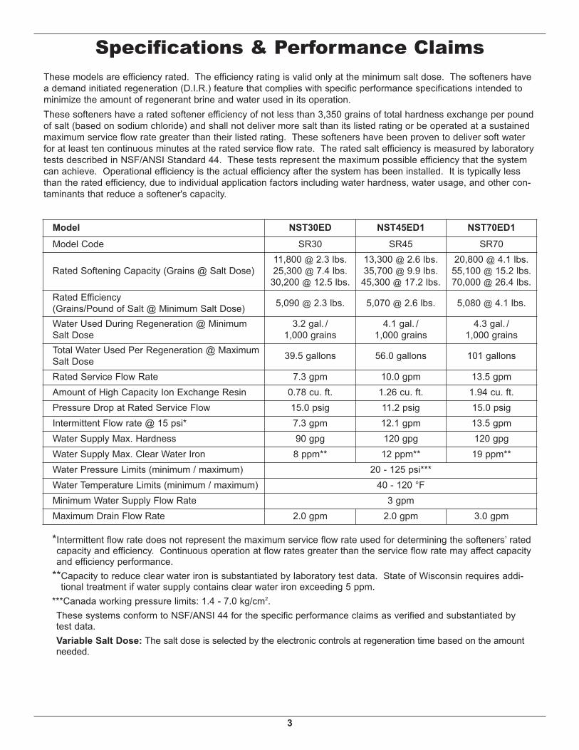
Specifications & Performance Claims
Model NST30ED NST45ED1 NST70ED1Model Code SR30 SR45 SR70
Rated Efficiency(Grains/Pound of Salt @ Minimum Salt Dose) 5,090 @ 2.3 lbs. 5,070 @ 2.6 lbs. 5,080 @ 4.1 lbs.
Water Used During Regeneration @ MinimumSalt Dose
3.2 gal. /1,000 grains
4.1 gal. /1,000 grains
4.3 gal. /1,000 grains
Total Water Used Per Regeneration @ MaximumSalt Dose 39.5 gallons 56.0 gallons 101 gallons
Rated Service Flow Rate 7.3 gpm 10.0 gpm 13.5 gpmAmount of High Capacity Ion Exchange Resin 0.78 cu. ft. 1.26 cu. ft. 1.94 cu. ft.Pressure Drop at Rated Service Flow 15.0 psig 11.2 psig 15.0 psigIntermittent Flow rate @ 15 psi* 7.3 gpm 12.1 gpm 13.5 gpmWater Supply Max. Hardness 90 gpg 120 gpg 120 gpgWater Supply Max. Clear Water Iron 8 ppm** 12 ppm** 19 ppm**Water Pressure Limits (minimum / maximum) 20 - 125 psi***Water Temperature Limits (minimum / maximum) 40 - 120 °FMinimum Water Supply Flow Rate 3 gpmMaximum Drain Flow Rate 2.0 gpm 2.0 gpm 3.0 gpm
These models are efficiency rated. The efficiency rating is valid only at the minimum salt dose. The softeners havea demand initiated regeneration (D.I.R.) feature that complies with specific performance specifications intended tominimize the amount of regenerant brine and water used in its operation.These softeners have a rated softener efficiency of not less than 3,350 grains of total hardness exchange per poundof salt (based on sodium chloride) and shall not deliver more salt than its listed rating or be operated at a sustainedmaximum service flow rate greater than their listed rating. These softeners have been proven to deliver soft waterfor at least ten continuous minutes at the rated service flow rate. The rated salt efficiency is measured by laboratorytests described in NSF/ANSI Standard 44. These tests represent the maximum possible efficiency that the systemcan achieve. Operational efficiency is the actual efficiency after the system has been installed. It is typically lessthan the rated efficiency, due to individual application factors including water hardness, water usage, and other con-taminants that reduce a softener's capacity.
*Intermittent flow rate does not represent the maximum service flow rate used for determining the softeners’ ratedcapacity and efficiency. Continuous operation at flow rates greater than the service flow rate may affect capacityand efficiency performance.
**Capacity to reduce clear water iron is substantiated by laboratory test data. State of Wisconsin requires addi-tional treatment if water supply contains clear water iron exceeding 5 ppm.
***Canada working pressure limits: 1.4 - 7.0 kg/cm2. These systems conform to NSF/ANSI 44 for the specific performance claims as verified and substantiated by test data. Variable Salt Dose: The salt dose is selected by the electronic controls at regeneration time based on the amountneeded.
4
18"DIA.
39"
C
14"
3-3/4"
OU
TLE
T
INLE
TINLET -OUTLET
AB
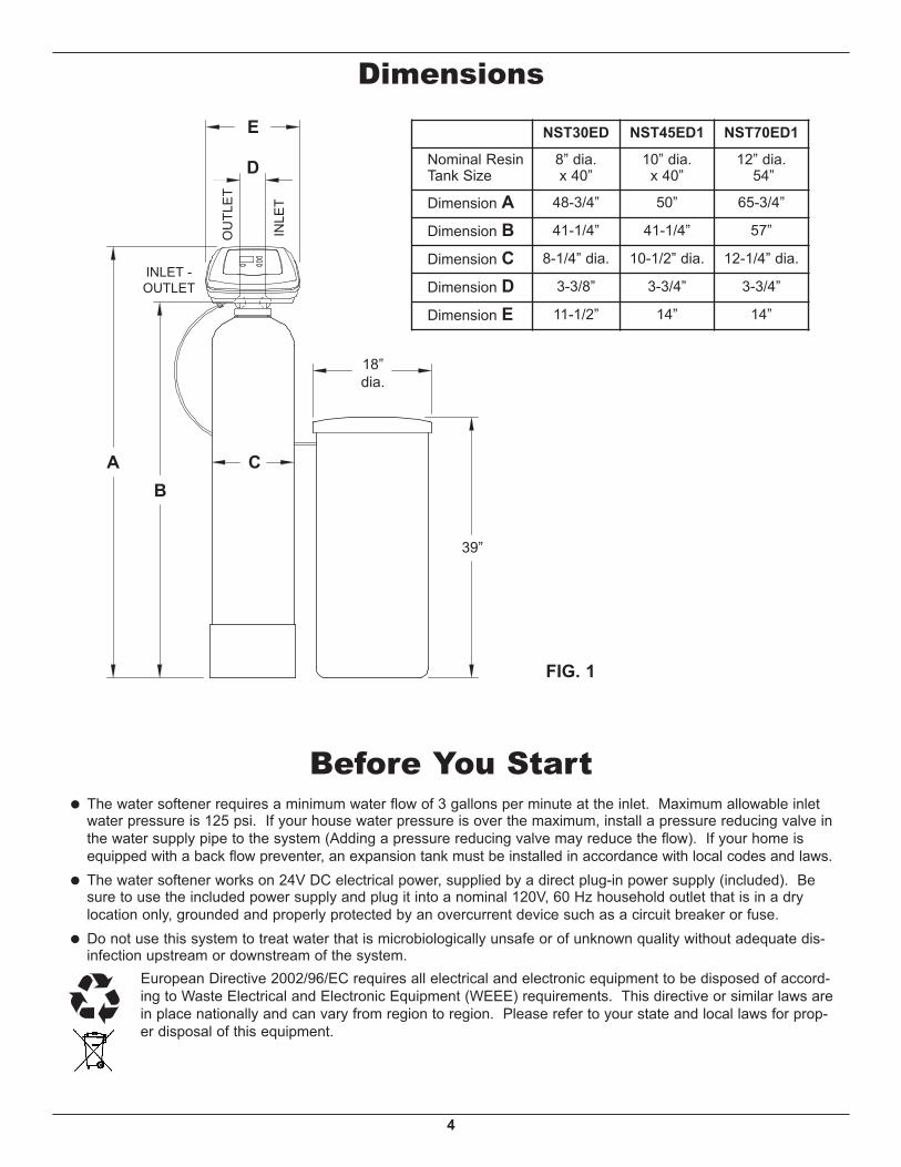
FIG. 1
Dimensions
INLE
T
OU
TLE
T
INLET -OUTLET
18”dia.
39”
AB
C
D
= The water softener requires a minimum water flow of 3 gallons per minute at the inlet. Maximum allowable inletwater pressure is 125 psi. If your house water pressure is over the maximum, install a pressure reducing valve inthe water supply pipe to the system (Adding a pressure reducing valve may reduce the flow). If your home isequipped with a back flow preventer, an expansion tank must be installed in accordance with local codes and laws.
= The water softener works on 24V DC electrical power, supplied by a direct plug-in power supply (included). Besure to use the included power supply and plug it into a nominal 120V, 60 Hz household outlet that is in a drylocation only, grounded and properly protected by an overcurrent device such as a circuit breaker or fuse.
= Do not use this system to treat water that is microbiologically unsafe or of unknown quality without adequate dis-infection upstream or downstream of the system.
European Directive 2002/96/EC requires all electrical and electronic equipment to be disposed of accord-ing to Waste Electrical and Electronic Equipment (WEEE) requirements. This directive or similar laws arein place nationally and can vary from region to region. Please refer to your state and local laws for prop-er disposal of this equipment.
Before You Start
NST30ED NST45ED1 NST70ED1
Nominal ResinTank Size
8” dia.x 40”
10” dia.x 40”
12” dia. 54”
Dimension A 48-3/4” 50” 65-3/4”
Dimension B 41-1/4” 41-1/4” 57”
Dimension C 8-1/4” dia. 10-1/2” dia. 12-1/4” dia.
Dimension D 3-3/8” 3-3/4” 3-3/4”
Dimension E 11-1/2” 14” 14”
E
5
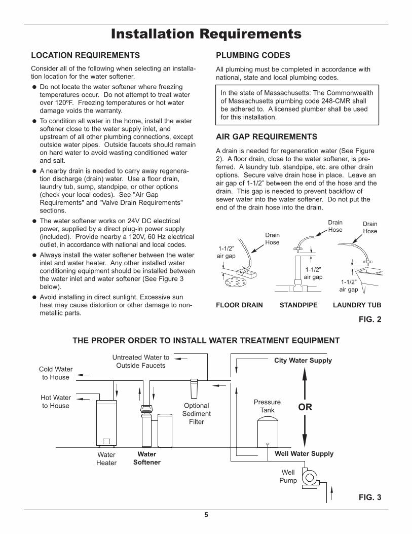
THE PROPER ORDER TO INSTALL WATER TREATMENT EQUIPMENT
FIG. 3
PressureTank
City Water Supply
Well Water Supply
WellPump
OROptionalSediment
Filter
WaterHeater
WaterSoftener
Untreated Water toOutside Faucets
Hot Waterto House
Cold Waterto House
LOCATION REQUIREMENTSConsider all of the following when selecting an installa-tion location for the water softener.= Do not locate the water softener where freezing
temperatures occur. Do not attempt to treat waterover 120ºF. Freezing temperatures or hot waterdamage voids the warranty.
= To condition all water in the home, install the watersoftener close to the water supply inlet, andupstream of all other plumbing connections, exceptoutside water pipes. Outside faucets should remainon hard water to avoid wasting conditioned waterand salt.
= A nearby drain is needed to carry away regenera-tion discharge (drain) water. Use a floor drain,laundry tub, sump, standpipe, or other options(check your local codes). See "Air GapRequirements" and "Valve Drain Requirements"sections.
= The water softener works on 24V DC electricalpower, supplied by a direct plug-in power supply(included). Provide nearby a 120V, 60 Hz electricaloutlet, in accordance with national and local codes.
= Always install the water softener between the waterinlet and water heater. Any other installed waterconditioning equipment should be installed betweenthe water inlet and water softener (See Figure 3below).
= Avoid installing in direct sunlight. Excessive sunheat may cause distortion or other damage to non-metallic parts.
Installation RequirementsPLUMBING CODESAll plumbing must be completed in accordance withnational, state and local plumbing codes.
LAUNDRY TUBSTANDPIPE
1-1/2”air gap
FLOOR DRAIN
In the state of Massachusetts: The Commonwealthof Massachusetts plumbing code 248-CMR shallbe adhered to. A licensed plumber shall be usedfor this installation.
AIR GAP REQUIREMENTSA drain is needed for regeneration water (See Figure2). A floor drain, close to the water softener, is pre-ferred. A laundry tub, standpipe, etc. are other drainoptions. Secure valve drain hose in place. Leave anair gap of 1-1/2” between the end of the hose and thedrain. This gap is needed to prevent backflow ofsewer water into the water softener. Do not put theend of the drain hose into the drain.
FIG. 2
1-1/2”air gap
DrainHose
DrainHose
1-1/2”air gap
DrainHose
6
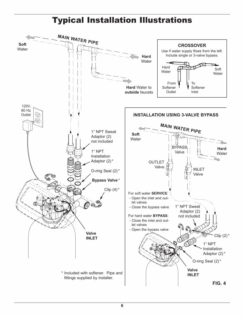
FIG. 4
SoftWater
HardWater
Hard Water tooutside faucets
CROSSOVERUse if water supply flows from the left.
Include single or 3-valve bypass.
MAIN WATER PIPE
HardWater
SoftWater
ToSoftenerInlet
FromSoftener
Outlet
1” NPT SweatAdaptor (2)not included
1” NPTInstallationAdaptor (2) *
O-ring Seal (2) *
Bypass Valve *
Clip (4) *
* Included with softener. Pipe andfittings supplied by installer.
ValveINLET
ValveINLET
1” NPTInstallationAdaptor (2) *
O-ring Seal (2) *
Clip (2) *
1” NPT SweatAdaptor (2)
not included
INLETValve
OUTLETValve
BYPASSValve
MAIN WATER PIPE
INSTALLATION USING 3-VALVE BYPASS
For soft water SERVICE:- Open the inlet and out-
let valves- Close the bypass valve
For hard water BYPASS:- Close the inlet and out-
let valves- Open the bypass valve
SoftWater
HardWater
120V,60 HzOutlet
Typical Installation Illustrations
7
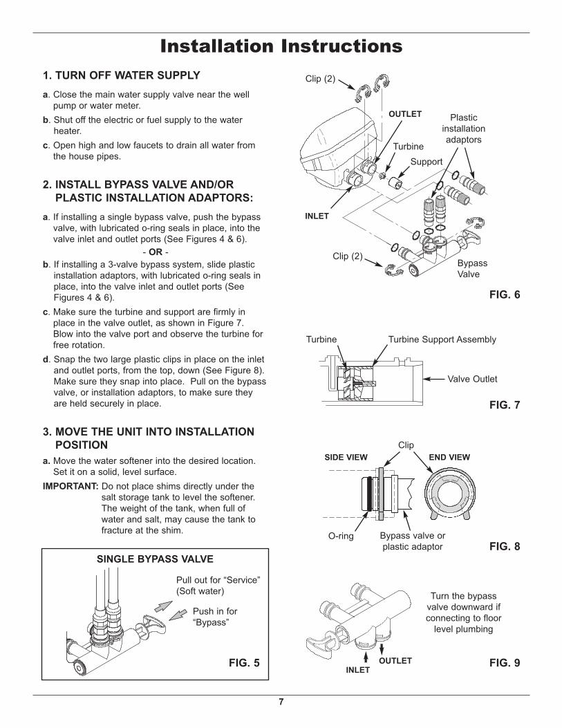
1. TURN OFF WATER SUPPLYa. Close the main water supply valve near the well
pump or water meter.b. Shut off the electric or fuel supply to the water
heater.c. Open high and low faucets to drain all water from
a. If installing a single bypass valve, push the bypassvalve, with lubricated o-ring seals in place, into thevalve inlet and outlet ports (See Figures 4 & 6).
- OR -b. If installing a 3-valve bypass system, slide plastic
installation adaptors, with lubricated o-ring seals inplace, into the valve inlet and outlet ports (SeeFigures 4 & 6).
c. Make sure the turbine and support are firmly inplace in the valve outlet, as shown in Figure 7.Blow into the valve port and observe the turbine forfree rotation.
d. Snap the two large plastic clips in place on the inletand outlet ports, from the top, down (See Figure 8).Make sure they snap into place. Pull on the bypassvalve, or installation adaptors, to make sure theyare held securely in place.
3. MOVE THE UNIT INTO INSTALLATIONPOSITION
a. Move the water softener into the desired location.Set it on a solid, level surface.
IMPORTANT: Do not place shims directly under thesalt storage tank to level the softener.The weight of the tank, when full ofwater and salt, may cause the tank tofracture at the shim.
FIG. 8O-ring
Clip
Bypass valve orplastic adaptor
END VIEWSIDE VIEW
FIG. 7
Turbine Turbine Support Assembly
Valve Outlet
FIG. 9
Turn the bypassvalve downward ifconnecting to floor
level plumbing
INLETOUTLETFIG. 5
SINGLE BYPASS VALVE
Pull out for “Service”(Soft water)
Push in for“Bypass”
FIG. 6
INLET
OUTLET
Clip (2)
BypassValve
Plasticinstallationadaptors
Clip (2)
TurbineSupport
Installation Instructions
8
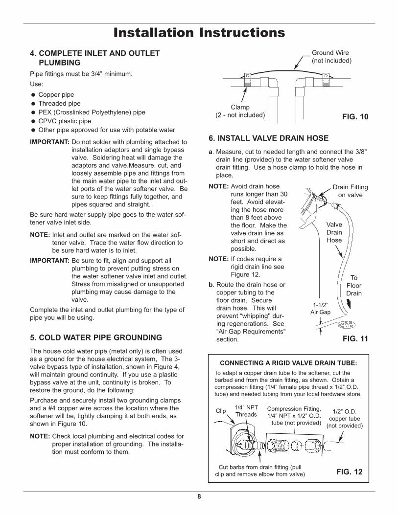
Installation Instructions4. COMPLETE INLET AND OUTLET
PLUMBINGPipe fittings must be 3/4” minimum.Use:= Copper pipe= Threaded pipe= PEX (Crosslinked Polyethylene) pipe= CPVC plastic pipe= Other pipe approved for use with potable water
IMPORTANT: Do not solder with plumbing attached toinstallation adaptors and single bypassvalve. Soldering heat will damage theadaptors and valve.Measure, cut, andloosely assemble pipe and fittings fromthe main water pipe to the inlet and out-let ports of the water softener valve. Besure to keep fittings fully together, andpipes squared and straight.
Be sure hard water supply pipe goes to the water sof-tener valve inlet side.
NOTE: Inlet and outlet are marked on the water sof-tener valve. Trace the water flow direction tobe sure hard water is to inlet.
IMPORTANT: Be sure to fit, align and support allplumbing to prevent putting stress onthe water softener valve inlet and outlet.Stress from misaligned or unsupportedplumbing may cause damage to thevalve.
Complete the inlet and outlet plumbing for the type ofpipe you will be using.
5. COLD WATER PIPE GROUNDINGThe house cold water pipe (metal only) is often usedas a ground for the house electrical system, The 3-valve bypass type of installation, shown in Figure 4,will maintain ground continuity. If you use a plasticbypass valve at the unit, continuity is broken. Torestore the ground, do the following:Purchase and securely install two grounding clampsand a #4 copper wire across the location where thesoftener will be, tightly clamping it at both ends, asshown in Figure 10.
NOTE: Check local plumbing and electrical codes forproper installation of grounding. The installa-tion must conform to them.
6. INSTALL VALVE DRAIN HOSEa. Measure, cut to needed length and connect the 3/8"
drain line (provided) to the water softener valvedrain fitting. Use a hose clamp to hold the hose inplace.
NOTE: Avoid drain hoseruns longer than 30feet. Avoid elevat-ing the hose morethan 8 feet abovethe floor. Make thevalve drain line asshort and direct aspossible.
NOTE: If codes require arigid drain line seeFigure 12.
b. Route the drain hose orcopper tubing to thefloor drain. Securedrain hose. This willprevent “whipping'' dur-ing regenerations. See“Air Gap Requirements"section. FIG. 11
Drain Fittingon valve
ValveDrainHose
1-1/2”Air Gap
ToFloorDrain
CONNECTING A RIGID VALVE DRAIN TUBE:To adapt a copper drain tube to the softener, cut thebarbed end from the drain fitting, as shown. Obtain acompression fitting (1/4” female pipe thread x 1/2” O.D.tube) and needed tubing from your local hardware store.
FIG. 12
1/4” NPTThreadsClip Compression Fitting,
1/4” NPT x 1/2” O.D.tube (not provided)
Cut barbs from drain fitting (pullclip and remove elbow from valve)
1/2” O.D.copper tube
(not provided)
FIG. 10
Ground Wire(not included)
Clamp(2 - not included)
9
Nozzle/Venturi
Ferrule Nut
BrineValve
Tubing
Brinewell
Grommet
HoseAdaptor
ToDrain
OverflowDrain Hose
BrinewellCover
Brine TankResin Tank FIG. 13
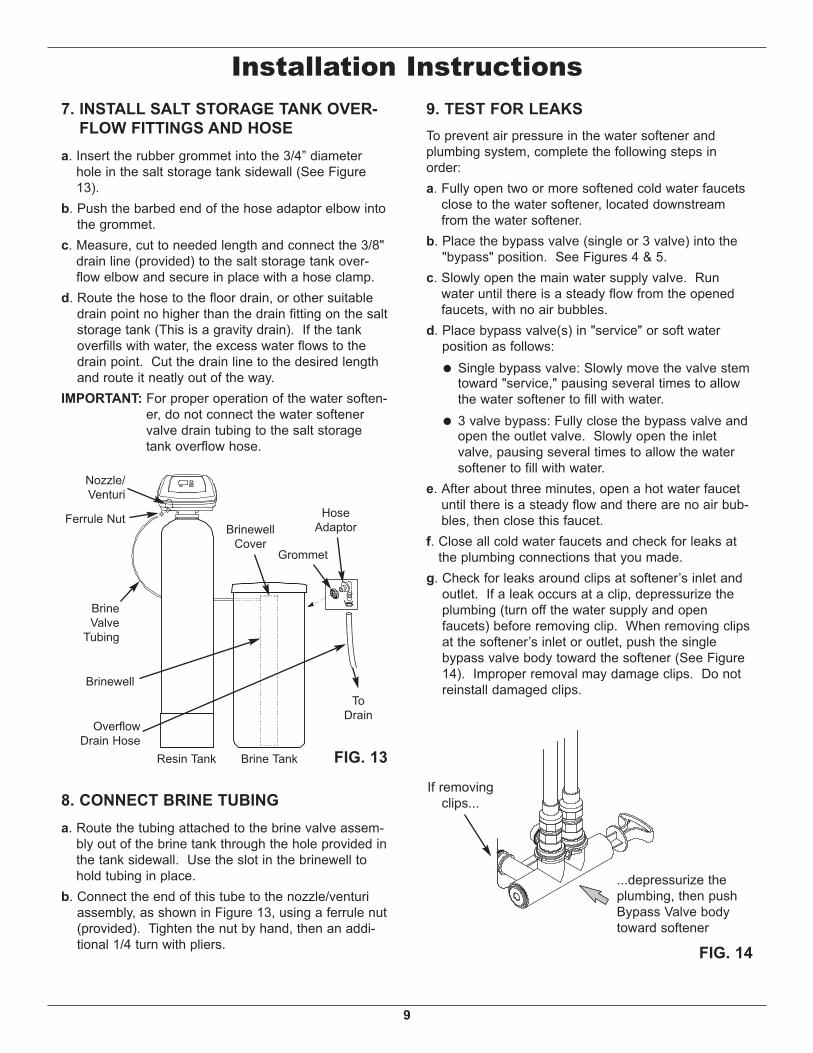
8. CONNECT BRINE TUBINGa. Route the tubing attached to the brine valve assem-
bly out of the brine tank through the hole provided inthe tank sidewall. Use the slot in the brinewell tohold tubing in place.
b. Connect the end of this tube to the nozzle/venturiassembly, as shown in Figure 13, using a ferrule nut(provided). Tighten the nut by hand, then an addi-tional 1/4 turn with pliers.
9. TEST FOR LEAKSTo prevent air pressure in the water softener andplumbing system, complete the following steps inorder:a. Fully open two or more softened cold water faucets
close to the water softener, located downstreamfrom the water softener.
b. Place the bypass valve (single or 3 valve) into the"bypass" position. See Figures 4 & 5.
c. Slowly open the main water supply valve. Runwater until there is a steady flow from the openedfaucets, with no air bubbles.
d. Place bypass valve(s) in "service" or soft waterposition as follows:
= Single bypass valve: Slowly move the valve stemtoward "service," pausing several times to allowthe water softener to fill with water.
= 3 valve bypass: Fully close the bypass valve andopen the outlet valve. Slowly open the inletvalve, pausing several times to allow the watersoftener to fill with water.
e. After about three minutes, open a hot water faucetuntil there is a steady flow and there are no air bub-bles, then close this faucet.
f. Close all cold water faucets and check for leaks atthe plumbing connections that you made.
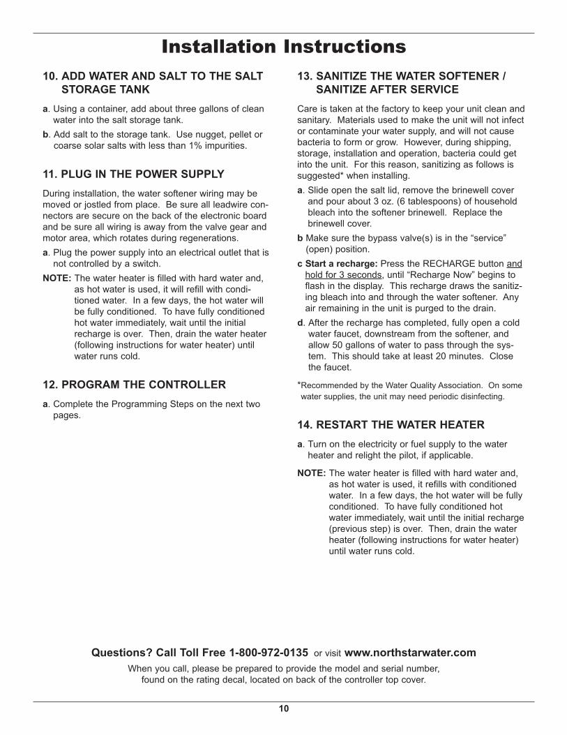
g. Check for leaks around clips at softener’s inlet andoutlet. If a leak occurs at a clip, depressurize theplumbing (turn off the water supply and openfaucets) before removing clip. When removing clipsat the softener’s inlet or outlet, push the singlebypass valve body toward the softener (See Figure14). Improper removal may damage clips. Do notreinstall damaged clips.
7. INSTALL SALT STORAGE TANK OVER-FLOW FITTINGS AND HOSE
a. Insert the rubber grommet into the 3/4” diameterhole in the salt storage tank sidewall (See Figure13).
b. Push the barbed end of the hose adaptor elbow intothe grommet.
c. Measure, cut to needed length and connect the 3/8"drain line (provided) to the salt storage tank over-flow elbow and secure in place with a hose clamp.
d. Route the hose to the floor drain, or other suitabledrain point no higher than the drain fitting on the saltstorage tank (This is a gravity drain). If the tankoverfills with water, the excess water flows to thedrain point. Cut the drain line to the desired lengthand route it neatly out of the way.
IMPORTANT: For proper operation of the water soften-er, do not connect the water softenervalve drain tubing to the salt storagetank overflow hose.
FIG. 14
...depressurize theplumbing, then pushBypass Valve bodytoward softener
If removingclips...
Installation Instructions
10
Installation Instructions10. ADD WATER AND SALT TO THE SALT
STORAGE TANKa. Using a container, add about three gallons of clean
water into the salt storage tank.b. Add salt to the storage tank. Use nugget, pellet or
coarse solar salts with less than 1% impurities.
11. PLUG IN THE POWER SUPPLYDuring installation, the water softener wiring may bemoved or jostled from place. Be sure all leadwire con-nectors are secure on the back of the electronic boardand be sure all wiring is away from the valve gear andmotor area, which rotates during regenerations.a. Plug the power supply into an electrical outlet that is
not controlled by a switch.NOTE: The water heater is filled with hard water and,
as hot water is used, it will refill with condi-tioned water. In a few days, the hot water willbe fully conditioned. To have fully conditionedhot water immediately, wait until the initialrecharge is over. Then, drain the water heater(following instructions for water heater) untilwater runs cold.
12. PROGRAM THE CONTROLLERa. Complete the Programming Steps on the next two
pages.
13. SANITIZE THE WATER SOFTENER /SANITIZE AFTER SERVICE
Care is taken at the factory to keep your unit clean andsanitary. Materials used to make the unit will not infector contaminate your water supply, and will not causebacteria to form or grow. However, during shipping,storage, installation and operation, bacteria could getinto the unit. For this reason, sanitizing as follows issuggested* when installing.a. Slide open the salt lid, remove the brinewell cover
and pour about 3 oz. (6 tablespoons) of householdbleach into the softener brinewell. Replace thebrinewell cover.
b Make sure the bypass valve(s) is in the “service”(open) position.
c Start a recharge: Press the RECHARGE button andhold for 3 seconds, until “Recharge Now” begins toflash in the display. This recharge draws the sanitiz-ing bleach into and through the water softener. Anyair remaining in the unit is purged to the drain.
d. After the recharge has completed, fully open a coldwater faucet, downstream from the softener, andallow 50 gallons of water to pass through the sys-tem. This should take at least 20 minutes. Closethe faucet.
*Recommended by the Water Quality Association. On somewater supplies, the unit may need periodic disinfecting.
14. RESTART THE WATER HEATERa. Turn on the electricity or fuel supply to the water
heater and relight the pilot, if applicable.
NOTE: The water heater is filled with hard water and,as hot water is used, it refills with conditionedwater. In a few days, the hot water will be fullyconditioned. To have fully conditioned hotwater immediately, wait until the initial recharge(previous step) is over. Then, drain the waterheater (following instructions for water heater)until water runs cold.
Questions? Call Toll Free 1-800-972-0135 or visit www.northstarwater.comWhen you call, please be prepared to provide the model and serial number,
found on the rating decal, located on back of the controller top cover.
11
Programming the Electronic Controller
CONTROLLER SETTINGS REQUIREDupon installation, and after an extended power outage.
When the power supply is plugged into the electricaloutlet, a model code (see table on page 3) and a soft-ware version number (example: J3.9), are brieflyshown in the display. Then the words “PRESENTTIME” appear and 12:00 PM begins to flash.
A. SET PRESENT TIME OF DAYIf the words “PRESENT TIME" do not show in the dis-play, press the SELECT button several times untilthey do.
FIG. 16
FIG. 17
2. When the correct time is displayed, press theSELECT button, and the display will change toshow the “Hardness” screen.
B. SET WATER HARDNESS NUMBERNOTE: If “HARDNESS” and a number do not show in
the display, press the SELECT button a fewtimes until they do.
1. Press the UP (È) or DOWN (–) buttons to set thepresent time. Up moves the display ahead; downsets the time back. Be sure AM or PM is correct.
NOTE: Press buttons and quickly release to slowlyadvance the display. Hold the buttons downfor fast advance.
1. Press the UP (È) or DOWN (–) buttons to set thevalue of your water’s hardness in grains per gallon(gpg).
NOTE: If your water supply contains iron, compen-sate for it by adding to the water hardnessnumber. For example, assume your water is20 gpg hard and contains 2 ppm iron. Add 5to the hardness number for each 1 ppm ofiron. In this example, you would use 30 foryour hardness number.
20 gpg hardness 2 ppm iron x 5 = 10 +10 (times) 30 HARDNESS NUMBER
2. When finished setting your water’s hardness num-ber, press the SELECT button, and the display willchange to show the “Recharge Time” screen.
FIG. 18
continued on next page
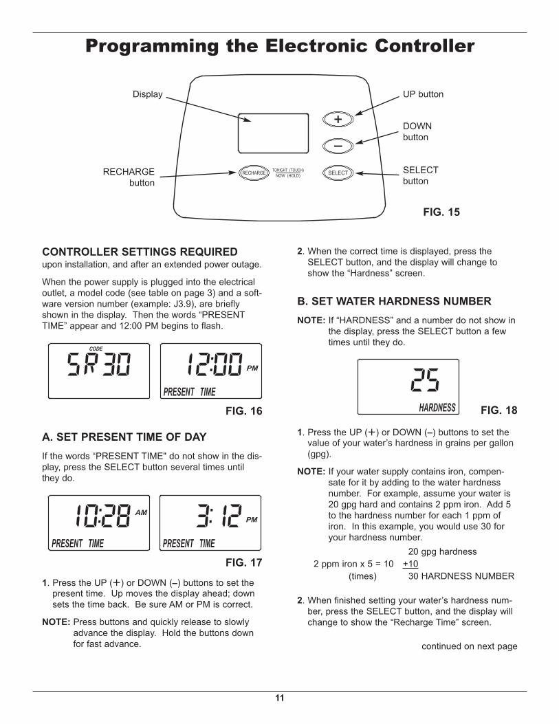
FIG. 15
UP button
DOWNbutton
Display
RECHARGEbutton
SELECTbutton
12
OPTIONAL RECHARGE CONTROLSSometimes a manually initiated regeneration (re -charge) may be desired or needed. Two examples:= You have used more water than usual (guests,
extra washing, etc.) and you may run out of softwater before the next scheduled regeneration.
= You did not refill the storage tank with salt before ithad run completely out.
Use one of the following two features to begin aregeneration either immediately or at the next presetregeneration start time:
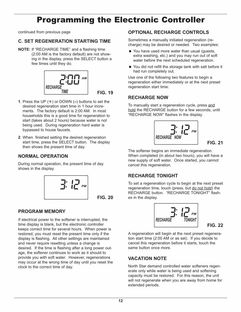
RECHARGE NOWTo manually start a regeneration cycle, press andhold the RECHARGE button for a few seconds, until“RECHARGE NOW” flashes in the display.
The softener begins an immediate regeneration.When completed (in about two hours), you will have anew supply of soft water. Once started, you cannotcancel this regeneration.
RECHARGE TONIGHTTo set a regeneration cycle to begin at the next presetregeneration time, touch (press, but do not hold) theRECHARGE button. “RECHARGE TONIGHT” flash-es in the display.
FIG. 21
A regeneration will begin at the next preset regenera-tion start time (2:00 AM or as set). If you decide tocancel this regeneration before it starts, touch thesame button once more.
VACATION NOTENorth Star demand controlled water softeners regen-erate only while water is being used and softeningcapacity must be restored. For this reason, the unitwill not regenerate when you are away from home forextended periods.
FIG. 22
Programming the Electronic Controller
FIG. 19
FIG. 20
continued from previous page
1. Press the UP (È) or DOWN (–) buttons to set thedesired regeneration start time in 1 hour incre-ments. The factory default is 2:00 AM. In mosthouseholds this is a good time for regeneration tostart (takes about 2 hours) because water is notbeing used. During regeneration hard water isbypassed to house faucets.
2. When finished setting the desired regenerationstart time, press the SELECT button. The displaythen shows the present time of day.
NORMAL OPERATIONDuring normal operation, the present time of dayshows in the display.
C. SET REGENERATION STARTING TIMENOTE: If “RECHARGE TIME” and a flashing time
(2:00 AM is the factory default) are not show-ing in the display, press the SELECT button afew times until they do.
PROGRAM MEMORYIf electrical power to the softener is interrupted, thetime display is blank, but the electronic controllerkeeps correct time for several hours. When power isrestored, you must reset the present time only if thedisplay is flashing. All other settings are maintainedand never require resetting unless a change isdesired. If the time is flashing after a long power out-age, the softener continues to work as it should toprovide you with soft water. However, regenerationsmay occur at the wrong time of day until you reset theclock to the correct time of day.
13
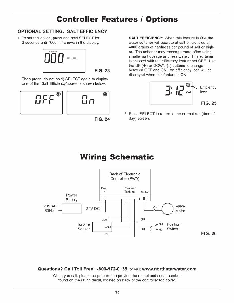
OPTIONAL SETTING: SALT EFFICIENCY1. To set this option, press and hold SELECT for
3 seconds until “000 - -” shows in the display.
Then press (do not hold) SELECT again to displayone of the “Salt Efficiency” screens shown below.
SALT EFFICIENCY: When this feature is ON, thewater softener will operate at salt efficiencies of4000 grains of hardness per pound of salt or high-er. The softener may recharge more often usingsmaller salt dosage and less water. This softeneris shipped with the efficiency feature set OFF. Usethe UP (È) or DOWN (–) buttons to changebetween OFF and ON. An efficiency icon will bedisplayed when this feature is ON.
Controller Features / Options
FIG. 23
FIG. 242. Press SELECT to return to the normal run (time of
day) screen.
FIG. 25
EfficiencyIcon
Questions? Call Toll Free 1-800-972-0135 or visit www.northstarwater.comWhen you call, please be prepared to provide the model and serial number,
found on the rating decal, located on back of the controller top cover.
FIG. 26
NO
ValveMotor
PositionSwitchNC
Back of ElectronicController (PWA)
Pwr.In
Position/Turbine Motor
24V DC120V AC
60Hz
PowerSupply
Corg
grn
TurbineSensor
+5
OUT
GND
Wiring Schematic
14
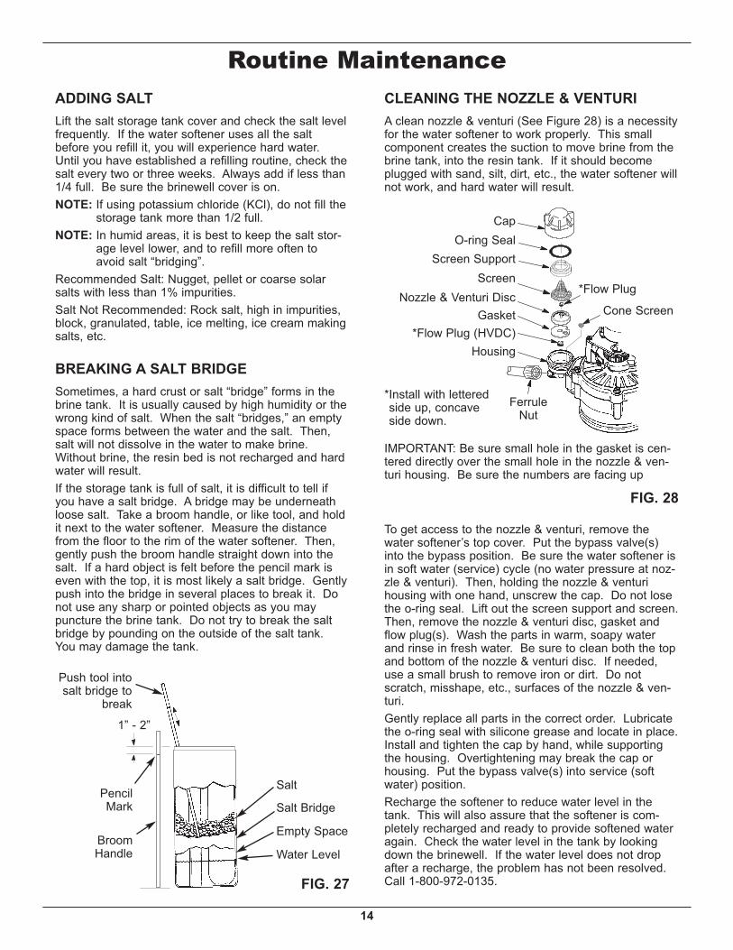
FIG. 27
BroomHandle
PencilMark
1” - 2”
Salt
Salt Bridge
Water Level
Push tool intosalt bridge to
break
FIG. 28
CapO-ring Seal
Screen SupportScreen
Gasket*Flow Plug (HVDC)
Housing
FerruleNut
Cone Screen
*Flow Plug
*Install with letteredside up, concaveside down.
CLEANING THE NOZZLE & VENTURIA clean nozzle & venturi (See Figure 28) is a necessityfor the water softener to work properly. This smallcomponent creates the suction to move brine from thebrine tank, into the resin tank. If it should becomeplugged with sand, silt, dirt, etc., the water softener willnot work, and hard water will result.
Nozzle & Venturi Disc
IMPORTANT: Be sure small hole in the gasket is cen-tered directly over the small hole in the nozzle & ven-turi housing. Be sure the numbers are facing up
Routine MaintenanceADDING SALTLift the salt storage tank cover and check the salt levelfrequently. If the water softener uses all the saltbefore you refill it, you will experience hard water.Until you have established a refilling routine, check thesalt every two or three weeks. Always add if less than1/4 full. Be sure the brinewell cover is on.NOTE: If using potassium chloride (KCl), do not fill the
storage tank more than 1/2 full.NOTE: In humid areas, it is best to keep the salt stor-
age level lower, and to refill more often toavoid salt “bridging”.
Recommended Salt: Nugget, pellet or coarse solarsalts with less than 1% impurities.Salt Not Recommended: Rock salt, high in impurities,block, granulated, table, ice melting, ice cream makingsalts, etc.
BREAKING A SALT BRIDGESometimes, a hard crust or salt “bridge” forms in thebrine tank. It is usually caused by high humidity or thewrong kind of salt. When the salt “bridges,” an emptyspace forms between the water and the salt. Then,salt will not dissolve in the water to make brine.Without brine, the resin bed is not recharged and hardwater will result.If the storage tank is full of salt, it is difficult to tell ifyou have a salt bridge. A bridge may be underneathloose salt. Take a broom handle, or like tool, and holdit next to the water softener. Measure the distancefrom the floor to the rim of the water softener. Then,gently push the broom handle straight down into thesalt. If a hard object is felt before the pencil mark iseven with the top, it is most likely a salt bridge. Gentlypush into the bridge in several places to break it. Donot use any sharp or pointed objects as you maypuncture the brine tank. Do not try to break the saltbridge by pounding on the outside of the salt tank.You may damage the tank.
To get access to the nozzle & venturi, remove thewater softener’s top cover. Put the bypass valve(s)into the bypass position. Be sure the water softener isin soft water (service) cycle (no water pressure at noz-zle & venturi). Then, holding the nozzle & venturihousing with one hand, un screw the cap. Do not losethe o-ring seal. Lift out the screen support and screen.Then, remove the nozzle & venturi disc, gasket andflow plug(s). Wash the parts in warm, soapy waterand rinse in fresh water. Be sure to clean both the topand bottom of the nozzle & venturi disc. If needed,use a small brush to remove iron or dirt. Do notscratch, misshape, etc., surfaces of the nozzle & ven-turi.Gently replace all parts in the correct order. Lubricatethe o-ring seal with silicone grease and locate in place.Install and tighten the cap by hand, while supportingthe housing. Overtightening may break the cap orhousing. Put the bypass valve(s) into service (softwater) position.Recharge the softener to reduce water level in thetank. This will also assure that the softener is com-pletely recharged and ready to provide softened wateragain. Check the water level in the tank by lookingdown the brinewell. If the water level does not dropafter a recharge, the problem has not been resolved.Call 1-800-972-0135.
Empty Space
15
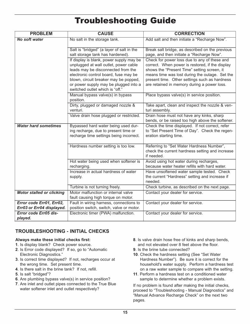
Troubleshooting GuidePROBLEM CAUSE CORRECTION
No soft water No salt in the storage tank. Add salt and then initiate a “Recharge Now”.
Salt is “bridged” (a layer of salt in thesalt storage tank has hardened).
Break salt bridge, as described on the previouspage, and then initiate a “Recharge Now”.
If display is blank, power supply may beunplugged at wall outlet, power cableleads may be disconnected from theelectronic control board, fuse may beblown, circuit breaker may be popped,or power supply may be plugged into aswitched outlet which is “off.”
Check for power loss due to any of these andcorrect. When power is restored, if the displayshows the “Present Time” setting screen, itmeans time was lost during the outage. Set thepresent time. Other settings such as hardnessare retained in memory during a power loss.
Manual bypass valve(s) in bypassposition.
Place bypass valve(s) in service position.
Dirty, plugged or damaged nozzle &venturi.
Take apart, clean and inspect the nozzle & ven-turi assembly.
Valve drain hose plugged or restricted. Drain hose must not have any kinks, sharpbends, or be raised too high above the softener.
Water hard sometimes Bypassed hard water being used dur-ing recharge, due to present time orrecharge time settings being incorrect.
Check the time displayed. If not correct, referto “Set Present Time of Day”. Check the regen-eration starting time.
Hardness number setting is too low. Referring to “Set Water Hardness Number”,check the current hardness setting and increaseif needed.
Hot water being used when softener isrecharging.
Avoid using hot water during recharges,because water heater refills with hard water.
Increase in actual hardness of watersupply.
Have unsoftened water sample tested. Checkthe current “Hardness” setting and increase ifneeded.
Turbine is not turning freely. Check turbine, as described on the next page.Motor stalled or clicking Motor malfunction or internal valve
fault causing high torque on motor.Contact your dealer for service.
Error code Err01, Err02,Err03 or Err04 displayed.
Fault in wiring harness, connections toposition switch, switch, valve or motor.
Contact your dealer for service.
Error code Err05 dis-played.
Electronic timer (PWA) malfunction. Contact your dealer for service.
TROUBLESHOOTING - INITIAL CHECKSAlways make these initial checks first:1. Is display blank? Check power source.2. Is Error code displayed? If so, go to “Automatic
Electronic Diagnostics.”3. Is correct time displayed? If not, recharges occur at
the wrong time. Set present time.4. Is there salt in the brine tank? If not, refill.5. Is salt “bridged”?6. Are plumbing bypass valve(s) in service position?7. Are inlet and outlet pipes connected to the True Blue
water softener inlet and outlet respectively?
8. Is valve drain hose free of kinks and sharp bends,and not elevated over 8 feet above the floor.
9. Is the brine tube connected?10. Check the hardness setting (See “Set Water
Hardness Number”). Be sure it is correct for thehousehold's water supply. Perform a hardness teston a raw water sample to compare with the setting.
11. Perform a hardness test on a conditioned watersample to determine whether a problem exists.
If no problem is found after making the initial checks,proceed to “Troubleshooting - Manual Diagnostics” and“Manual Advance Recharge Check” on the next twopages.
16
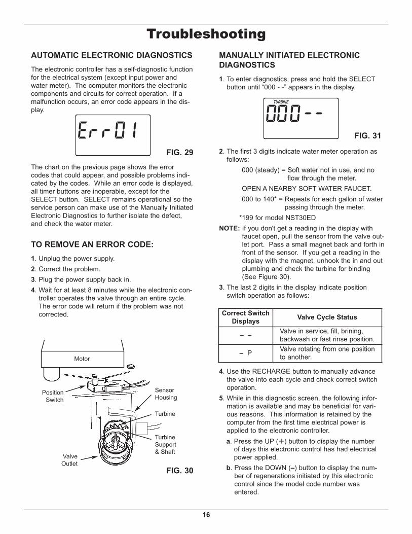
TroubleshootingAUTOMATIC ELECTRONIC DIAGNOSTICSThe electronic controller has a self-diagnostic functionfor the electrical system (except input power andwater meter). The computer monitors the electroniccomponents and circuits for correct operation. If amalfunction occurs, an error code appears in the dis-play.
FIG. 29
FIG. 30
The chart on the previous page shows the errorcodes that could appear, and possible problems indi-cated by the codes. While an error code is displayed,all timer buttons are inoperable, except for theSELECT button. SELECT remains operational so theservice person can make use of the Manually InitiatedElectronic Diagnostics to further isolate the defect,and check the water meter.
TO REMOVE AN ERROR CODE:1. Unplug the power supply.2. Correct the problem.3. Plug the power supply back in.4. Wait for at least 8 minutes while the electronic con-
troller operates the valve through an entire cycle.The error code will return if the problem was notcorrected.
FIG. 31
MANUALLY INITIATED ELECTRONICDIAGNOSTICS1. To enter diagnostics, press and hold the SELECT
button until “000 - -” appears in the display.
2. The first 3 digits indicate water meter operation asfollows:
000 (steady) = Soft water not in use, and noflow through the meter.
OPEN A NEARBY SOFT WATER FAUCET. 000 to 140* = Repeats for each gallon of water
passing through the meter.*199 for model NST30ED
NOTE: If you don't get a reading in the display withfaucet open, pull the sensor from the valve out-let port. Pass a small magnet back and forth infront of the sensor. If you get a reading in thedisplay with the magnet, unhook the in and outplumbing and check the turbine for binding(See Figure 30).
3. The last 2 digits in the display indicate positionswitch operation as follows:
4. Use the RECHARGE button to manually advancethe valve into each cycle and check correct switchoperation.
5. While in this diagnostic screen, the following infor-mation is available and may be beneficial for vari-ous reasons. This information is retained by thecomputer from the first time electrical power isapplied to the electronic controller.
a. Press the UP (È) button to display the numberof days this electronic control has had electricalpower applied.
b. Press the DOWN (–) button to display the num-ber of regenerations initiated by this electroniccontrol since the model code number wasentered.
Correct SwitchDisplays Valve Cycle Status
– – Valve in service, fill, brining,backwash or fast rinse position.
– P Valve rotating from one positionto another.Motor
ValveOutlet
PositionSwitch
SensorHousing
Turbine
TurbineSupport& Shaft
17
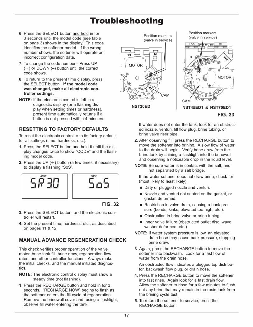
FIG. 33
This check verifies proper operation of the valvemotor, brine tank fill, brine draw, regeneration flowrates, and other controller functions. Always makethe initial checks, and the manual initiated diagnos-tics.NOTE: The electronic control display must show a
steady time (not flashing).1. Press the RECHARGE button and hold in for 3
seconds. “RECHARGE NOW” begins to flash asthe softener enters the fill cycle of regeneration.Remove the brinewell cover and, using a flashlight,observe fill water entering the tank.
MANUAL ADVANCE REGENERATION CHECK
Troubleshooting6. Press the SELECT button and hold in for
3 seconds until the model code (see tableon page 3) shows in the display. This codeidentifies the softener model. If the wrongnumber shows, the softener will operate onincorrect configuration data.
7. To change the code number - Press UP(È) or DOWN (–) button until the correctcode shows.
8. To return to the present time display, pressthe SELECT button. If the model codewas changed, make all electronic con-troller settings.
NOTE: If the electronic control is left in adiagnostic display (or a flashing dis-play when setting times or hardness),present time automatically returns if abutton is not pressed within 4 minutes.
3. Press the SELECT button, and the electronic con-troller will restart.
4. Set the present time, hardness, etc., as describedon pages 11 & 12.
If water does not enter the tank, look for an obstruct-ed nozzle, venturi, fill flow plug, brine tubing, orbrine valve riser pipe.
2. After observing fill, press the RECHARGE button tomove the softener into brining. A slow flow of waterto the drain will begin. Verify brine draw from thebrine tank by shining a flashlight into the brinewelland observing a noticeable drop in the liquid level.
NOTE: Be sure water is in contact with the salt, andnot separated by a salt bridge.
If the water softener does not draw brine, check for(most likely to least likely):
= Dirty or plugged nozzle and venturi. = Nozzle and venturi not seated on the gasket, or
gasket deformed. = Restriction in valve drain, causing a back-pres-
sure (bends, kinks, elevated too high, etc.). = Obstruction in brine valve or brine tubing = Inner valve failure (obstructed outlet disc, wave
washer deformed, etc.)NOTE: If water system pressure is low, an elevated
drain hose may cause back pressure, stoppingbrine draw.
3. Again, press the RECHARGE button to move thesoftener into backwash. Look for a fast flow ofwater from the drain hose.
An obstructed flow indicates a plugged top distribu-tor, backwash flow plug, or drain hose.
4. Press the RECHARGE button to move the softenerinto fast rinse. Again look for a fast drain flow.Allow the softener to rinse for a few minutes to flushout any brine that may remain in the resin tank fromthe brining cycle test.
5. To return the softener to service, press theRECHARGE button.
FIG. 32
NST45ED1 & NST70ED1
MOTOR
CAM
Position markers(valve in service)Position markers
(valve in service)
CAM
MOTOR
NST30ED
RESETTING TO FACTORY DEFAULTSTo reset the electronic controller to its factory defaultfor all settings (time, hardness, etc.):1. Press the SELECT button and hold it until the dis-
play changes twice to show “CODE” and the flash-ing model code.
2. Press the UP (È) button (a few times, if necessary)to display a flashing “SoS”.
18
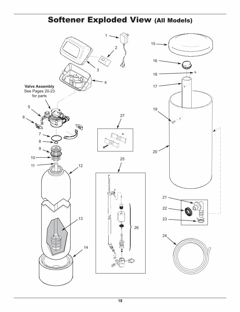
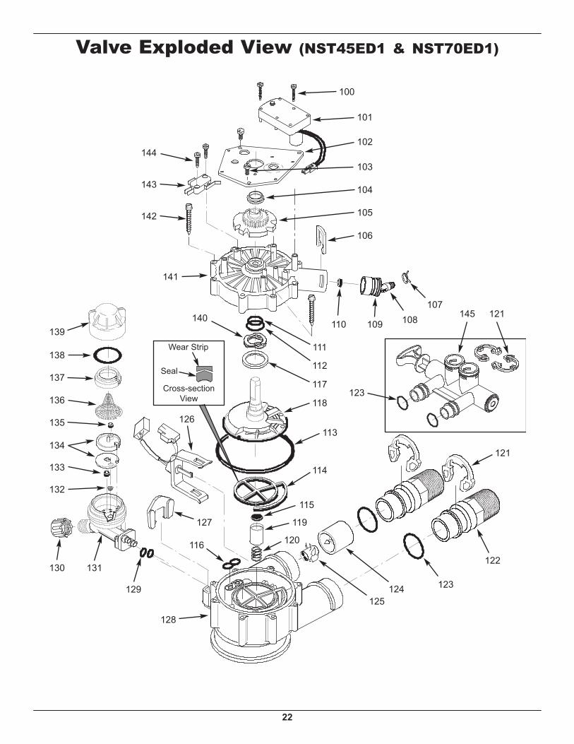
Softener Exploded View (All Models)
Valve AssemblySee Pages 20-23
for parts
5
6
7
8
9
10
11
13
12
4
3
2
18
17
1927
25
20
21
22
23
26
24
15
16
1
14
19
KeyNo. Part No. Description
1 7351054 Power Supply, 24V DC
2 7309358 Repl.Electronic Control Board(PWA)
3
7180291 Faceplate Cover, NST30ED(also order following decal)
7260554Faceplate Cover,NST45ED1 & NST70ED1(also order following decal)
– 7185487 Seal Kit (includes Key Nos. 111-116)111 á O-Ring, 5/8” x 13/16”112 á O-Ring, 1-1/8” x 1-1/2”113 á O-Ring, 4-1/2” x 4-7/8”114 á Rotor Seal115 á Seal116 á Seal, Nozzle & Venturi117 7174313 Bearing, Wave Washer118 7185500 Rotor & Disc