Modern Molar Endodontic Access and Directed Dentin Conservation David Clark, DDS a, *, John Khademi, DDS, MS b During patient treatment, the clinician needs to consider many factors that will affect the ultimate outcome. In simple terms, these factors can be grouped into 3 categories: the operator needs, the restoration needs, and the tooth needs. The operator needs are the conditions the clinician needs to treat the tooth. The restoration needs are the prep dimensions and tooth conditions for optimal strength and longevity. The tooth needs are the biologic and structural limitations for a treated tooth to remain predict- ably functional. This article discusses molar access and failures of endodontically treated teeth that occur not because of chronic or acute apical lesions but because of structural compromises to the teeth that ultimately renders them useless. What both authors have discovered in their respective practices through careful observa- tions of failing cases and modes of failure, and observation of the truly long-term (decades) successful cases, is that the current models of endodontic treatment do not lead to long-term success. The authors want to coronally shift the focus to the cervical area of the tooth and create awareness for an endorestorative interface. This article introduces a set of criteria that will guide the clinician in treatment deci- sions to maintain optimal functionality of the tooth and help in deciding whether the treatment prognosis is poor and alternatives should be considered. This article is not an update on traditional endodontic access, as the authors believe the traditional approach to endodontic access is fundamentally flawed. Traditional endodontic access has been endodontic centric, primarily focused on operator needs, and has been decoupled from the restorative needs and tooth needs. Central to our philosophy is that balance needs to be restored to these 3 needs, which are almost always in conflict when performing complete cusp-tip to root-tip treatment. Disclosure: Drs Clark and Khademi will receive a royalty from the sales of CK Endodontic Access burs. http://www.sswhiteburs.com. a 3402 South 38th Street, Tacoma, WA 98409, USA b 2277 West 2nd Avenue, Durango, CO 81301-4658, USA * Corresponding author. E-mail address: [email protected]KEYWORDS Molar Endodontic Access Dentin Dent Clin N Am 54 (2010) 249–273 doi:10.1016/j.cden.2010.01.001 dental.theclinics.com 0011-8532/10/$ – see front matter ª 2010 Elsevier Inc. All rights reserved.
Transcript
Modern MolarEndodontic Accessand Directed DentinConservation
David Clark, DDSa,*, John Khademi, DDS, MSb
KEYWORDS
� Molar � Endodontic � Access � Dentin
During patient treatment, the clinician needs to consider many factors that will affectthe ultimate outcome. In simple terms, these factors can be grouped into 3 categories:the operator needs, the restoration needs, and the tooth needs. The operator needsare the conditions the clinician needs to treat the tooth. The restoration needs arethe prep dimensions and tooth conditions for optimal strength and longevity. The toothneeds are the biologic and structural limitations for a treated tooth to remain predict-ably functional. This article discusses molar access and failures of endodonticallytreated teeth that occur not because of chronic or acute apical lesions but becauseof structural compromises to the teeth that ultimately renders them useless. Whatboth authors have discovered in their respective practices through careful observa-tions of failing cases and modes of failure, and observation of the truly long-term(decades) successful cases, is that the current models of endodontic treatment donot lead to long-term success. The authors want to coronally shift the focus to thecervical area of the tooth and create awareness for an endorestorative interface.This article introduces a set of criteria that will guide the clinician in treatment deci-sions to maintain optimal functionality of the tooth and help in deciding whether thetreatment prognosis is poor and alternatives should be considered. This article isnot an update on traditional endodontic access, as the authors believe the traditionalapproach to endodontic access is fundamentally flawed. Traditional endodonticaccess has been endodontic centric, primarily focused on operator needs, and hasbeen decoupled from the restorative needs and tooth needs. Central to our philosophyis that balance needs to be restored to these 3 needs, which are almost always inconflict when performing complete cusp-tip to root-tip treatment.
Disclosure: Drs Clark and Khademi will receive a royalty from the sales of CK Endodontic Accessburs. http://www.sswhiteburs.com.a 3402 South 38th Street, Tacoma, WA 98409, USAb 2277 West 2nd Avenue, Durango, CO 81301-4658, USA* Corresponding author.E-mail address: [email protected]
Dent Clin N Am 54 (2010) 249–273doi:10.1016/j.cden.2010.01.001 dental.theclinics.com0011-8532/10/$ – see front matter ª 2010 Elsevier Inc. All rights reserved.
SETTING THE STAGE FOR CONTEMPORARY MOLAR ENDODONTIC ACCESS
Modern clinicians must factor the unique and dramatically higher biting force of themolar tooth when designing the endodontic portion of the endo-endorestorative-pros-thodontic (EERP) continuum. The occlusal forces created by the attachment positionof the elevator muscles to the mandible generate occlusal forces that vary dramaticallythroughout the dentition, with light biting force in the front of the mouth to increasinglyheavier forces at the back of the mouth. In physics, the mandible with its hingedaccess (the temporomandibular joint) is classified as a moment arm. The closer tothe hinge, the higher the moment, or force, applied. The ability of the incisor to splayforward when loaded occlusally also comes into play when evaluating tooth stressesduring occlusal loading. However, the molar absorbs a more vertical force and, there-fore, a significantly higher net compressive force. When these 2 factors are combined(moment arm and splay), the overall compressive forces on the molar create a situationthat requires a different set of rules for the calculation of ferrule, post and core design,resistance to fracturing, and (of utmost importance) endodontic access and removal ofradicular dentin during endodontic shaping.
There are also different forces. The incisor must withstand milder, but more oblique,shearing forces. Most of the in vitro and in vivo research of post and core design hasbeen conducted on maxillary incisor teeth, and attempting to extrapolate these find-ings to the molar tooth is not feasible. Placing a post in a round, husky maxillary ante-rior root and subjecting it to mild shearing force has little relevance to placing a post ina delicate, ovoid root in a mandibular molar and subjecting it to heavy compressiveforce.
Box 1 presents a compelling argument for change, or, perhaps, a return to the pre-Schilder era of directed dentin conservation. Many people were hopeful that thepromise of point number 1, the endodontic monoblock of bonded endodontic obtu-rants, posts, and cores, could revitalize a hollowed-out tooth. This has not reachedfruition. Most restorative dentists are unaware of point number 2. Most have alwaysassumed that coronal composite restorations, especially those that are bonded toenamel, strengthen the crown of the tooth and prevent coronal fracturing. Thiscommon notion has created a false hope, as no such intracoronal splinting benefitexists. Point number 4 eliminates posts as a reconstructive asset in molars. Point 5presents the troubling fact that altering the thickness of radicular dentin, especiallyin the ovoid and fluted root, predisposes the root to fracture. Yet the dentin in theendodontically treated tooth has virtually the same strength and moisture contentas a tooth with intact pulp. Root fractures in endodontically treated teeth should beconsidered as iatrogenically generated, not because of any fault of the tooth. Theauthors have exhausted the means to reinforce the endodontically treated molarstump, and now realize that dentin is the key.
Box 1
Current research and restorative trends
(1) The failure of the endodontic monoblock1
(2) The failure of intracoronal splinting using adhesive dentistry2
(3) The resurgence of partial coverage posterior restorations
(4) The recognition that molars do not benefit from placement of posts3
(5) Crack initiation in stress tests of endodontically treated roots4,5
Molar Endodontic Access and Dentin Conservation 251
Endodontic accesses are traditionally conservative to the occlusal/incisal toothstructure. However, with the changes that occur in restorative dentistry, this techniqueis unnecessarily restrictive for the operator and potentially damaging to the more crit-ical cervical area of the tooth.
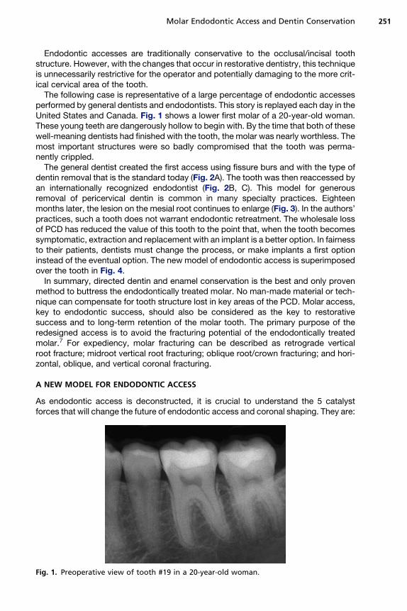
The following case is representative of a large percentage of endodontic accessesperformed by general dentists and endodontists. This story is replayed each day in theUnited States and Canada. Fig. 1 shows a lower first molar of a 20-year-old woman.These young teeth are dangerously hollow to begin with. By the time that both of thesewell-meaning dentists had finished with the tooth, the molar was nearly worthless. Themost important structures were so badly compromised that the tooth was perma-nently crippled.
The general dentist created the first access using fissure burs and with the type ofdentin removal that is the standard today (Fig. 2A). The tooth was then reaccessed byan internationally recognized endodontist (Fig. 2B, C). This model for generousremoval of pericervical dentin is common in many specialty practices. Eighteenmonths later, the lesion on the mesial root continues to enlarge (Fig. 3). In the authors’practices, such a tooth does not warrant endodontic retreatment. The wholesale lossof PCD has reduced the value of this tooth to the point that, when the tooth becomessymptomatic, extraction and replacement with an implant is a better option. In fairnessto their patients, dentists must change the process, or make implants a first optioninstead of the eventual option. The new model of endodontic access is superimposedover the tooth in Fig. 4.
In summary, directed dentin and enamel conservation is the best and only provenmethod to buttress the endodontically treated molar. No man-made material or tech-nique can compensate for tooth structure lost in key areas of the PCD. Molar access,key to endodontic success, should also be considered as the key to restorativesuccess and to long-term retention of the molar tooth. The primary purpose of theredesigned access is to avoid the fracturing potential of the endodontically treatedmolar.7 For expediency, molar fracturing can be described as retrograde verticalroot fracture; midroot vertical root fracturing; oblique root/crown fracturing; and hori-zontal, oblique, and vertical coronal fracturing.
A NEW MODEL FOR ENDODONTIC ACCESS
As endodontic access is deconstructed, it is crucial to understand the 5 catalystforces that will change the future of endodontic access and coronal shaping. They are:
Fig. 1. Preoperative view of tooth #19 in a 20-year-old woman.
Fig. 2. (A) The deroofing problem. The likely bur used by the referring general dentist isa 56 carbide; one of the most popular burs in dentistry,6 it is possibly the most iatrogenicinstrument in modern medicine. Red arrow delineates the typical gouging. (B) Postoperativeview provided by the endodontist. Blue arrow indicates the grossly excessive dentin removalof pericervical dentin (PCD). This serious gouging is typical of round bur access. Yellowarrow indicates the large canal flaring with unacceptable dentin removal (blind funneling).(C) Green circle highlights worsening lesion on mesial root ends.
Clark & Khademi252
1. Implant success rates2. Operating microscopes and micro-endodontics3. Biomimetic dentistry4. Minimally invasive dentistry5. Esthetic demands of patients.
In both of the authors’ practices, the endodontic goals and armamentarium havebeen in a constant state of flux for nearly a decade as we have collaborated to bringthe EERP continuum to maturity. The goal is to satisfy the demands of the big 5 forcesfor change mentioned earlier. In so doing, we have come to realize that, when cuttingendodontic access, our previous needs as dentists were often in conflict with theneeds of the tooth.
Table 1 presents the hierarchy of needs to maintain optimal strength, fracture resis-tance, and several other characteristics needed for long-term full function of theendodontically treated tooth. Banking of tooth structure is key and is age- andcase-sensitive. For example, in the case of the importance of pericervical enamel,the cementoenamel junction (CEJ) is an invaluable asset in the physiologically youngmolar. Margins of direct and indirect restorations placed on enamel have been shown
Fig. 3. Eighteen-month follow-up. Despite generous access and aggressive canal enlarge-ment, the lesion on the mesial root continues to enlarge.
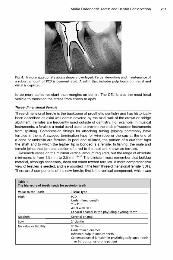
Fig. 4. A more appropriate access shape is overlayed. Partial deroofing and maintenance ofa robust amount of PCD is demonstrated. A soffit that includes pulp horns on mesial anddistal is depicted.
Molar Endodontic Access and Dentin Conservation 253
to be more caries resistant than margins on dentin. The CEJ is also the most idealvehicle to transition the stress from crown to apex.
Three-dimensional Ferrule
Three-dimensional ferrule is the backbone of prosthetic dentistry and has historicallybeen described as axial wall dentin covered by the axial wall of the crown or bridgeabutment. Ferrules are frequently used outside of dentistry. For example, in musicalinstruments, a ferule is a metal band used to prevent the ends of wooden instrumentsfrom splitting. Compression fittings for attaching tubing (piping) commonly haveferrules in them. A swaged termination type for wire rope or the cap at the end ofa cane or umbrella are ferrules. In pool and billiards, the portion of a cue that topsthe shaft and to which the leather tip is bonded is a ferrule. In fishing, the male andfemale joints that join one section of a rod to the next are known as ferrules.
Research varies on the minimal vertical amount required, but the range of absoluteminimums is from 1.5 mm to 2.5 mm.8–23 The clinician must remember that buildupmaterial, although necessary, does not count toward ferrules. A more comprehensiveview of ferrules is needed, and is embodied in the term three-dimensional ferrule (3DF).There are 3 components of the new ferrule; first is the vertical component, which was
Table 1The hierarchy of tooth needs for posterior teeth
Value to the Tooth Tissue Type
High PCDUndermined dentinThe D2JAxial wall DEJCervical enamel in the physiologic young tooth
Medium Coronal enamel
Low 2� dentin
No value or liability 3� DentinUndermined enamelInflamed pulp in mature teethCementoenamel junction in physiologically aged tooth
or in root caries–prone patient
Clark & Khademi254
described earlier, and is the traditional ferrule. The second component is dentin girth(thickness). The absolute minimum thickness is 1 mm; however, 2 mm is obviouslya safer number. Girth becomes more important closer to the finish lines of the prepa-ration. The thickness of the remaining dentin (the wall thickness) between the externalsurface of the tooth at the finish line and the endodontic access is more importantapically. Further, progressing apically down onto the root surface in the endodonticallytreated tooth, the wall thickness can vary considerably and can become thin in places,especially if large coronal shaping or flaring was done during the endodontic treat-ment. Thus, axially deep finish lines on root structure can be extremely damaging to3DF. Gutta percha is an exceptionally poor core material. The third component is totalocclusal convergence (TOC) or net taper. TOC is the total draw of the 2 opposing axialwalls of the prepared tooth to receive a fixed crown. A net taper or TOC of 10� requires3 mm of vertical ferrule; a TOC of 20� requires 4 mm of vertical ferrule.24–37 Deepchamfer marginal zones, common with modern porcelain crowns, typically havea net taper of 50� or more, and therefore many modern esthetic margins lose a milli-meter or more of their original potential 3DF at the crown margin interface. In short,typical modern porcelain crown prep has less 3DF than the corresponding gold crownprep. Hence, the need for directed dentin conservation during endodontic accessbecomes even more crucial, and, at the same time, the volume of dentin removedin the axial direction should be questioned in the modern era of high-strength zirconiacore crowns that actually allow minimal axiomarginal reduction. In certain case typesand finish line designs, the degree of apical placement of the finish line can affect theferrule quality, as mentioned earlier. Light axiomarginal reduction coupled with apicallyplaced finish lines and a nonzero-degree emergence profile of the restoration canprovide high 3DF. The concept of 3DF incorporates an interplay between these factorsthat, in sum, indicate the true ferrule quality.
Undermined Enamel Versus Undermined Dentin
Because undermined enamel has not been shown to be strengthened by resin resto-rations, it becomes a liability because of fracture potential, poor C factor, and asa physical and visual obstruction to the endodontic operator. Conversely, becausedentin acts as a trimodal composite, it can be of great value to the tooth whetherthe undermined dentin occurs naturally, such as the soffit, or from previous restor-ative/endodontic treatment. It is important to clarify that the act of purposely under-mining dentin for mechanical retention of restorative materials or when using roundburs in endodontic access is no longer indicated in contemporary restorative andendodontic dentistry. Enamel is essentially a crystalline structure and is thereforenaturally supported 100% by dentin. Dentin, by contrast, is a multilevel compositethat can stand alone and acts ideally as a semirigid pipe.
PCD
PCD is the dentin near the alveolar crest. Although the apex of the root can be ampu-tated, and the coronal third of the clinical crown removed and replaced prosthetically,the dentin near the alveolar crest is irreplaceable. This critical zone, roughly 4 mmabove the crestal bone and extending 4 mm apical to the crestal bone, is importantfor 3 reasons: ferrule, fracturing, and dentin tubule orifice proximity from inside toout. The research is unequivocal; long-term retention of the tooth and resistance tofracturing are directly related to the amount of residual tooth structure.9,11 The moredentin is kept, the longer the tooth is kept.
Molar Endodontic Access and Dentin Conservation 255
SACRIFICE VERSUS COMPROMISE
In the featured case, significant dentin was sacrificed to facilitate expedient and safe(avoidance of rotary file separation) instrumentation. No compromise was made increating a direct pathway to the apices allowing copious irrigation and full verticalcompaction of heated gutta percha, and yet the endodontic treatment was failing.Contrast that case with the tooth in Fig. 5. There was a significant compromisewhen the dentist, 20 years ago, stopped removing dentin when he or she could notfind the canal systems and filled less than half of the distal root. Yet the poorendodontic result is successful, the well-preserved PCD has buttressed the tooth,and the overall case is a still a success after 20 years. The authors have seen manycases of seemingly poor endodontic results that have defied current and conventionalendodontic wisdom. Without detracting from the Schilder Objectives, the case typesthat seem to be lacking in the long-term are those with the appearance of high-qualityendodontics, namely generous endodontic access, continuous taper, and largeshape, facilitating the compaction of warm gutta percha.
LOOK, GROOM, AND FOLLOW: SHAPING VERSUS MACHINING
(1) Why are Gates Glidden (GG) burs so problematic? Since the introduction ofrotary files, GG burs have been used more aggressively and with more relianceon larger sizes (4, 5 and 6) to reduce binding and fracture of rotary files. Gatesburs have always been considered safe because they do not end cut and areself-centering. There is a significant problem here, which is cervical selfcentering. Because the shank of the GG is so thin, it is difficult to steer theGG away from high-risk anatomy. As the GG straightens the coronal or highcurve, it can shortcut across a fluting or furcation and weaken or even createstrip perforations (Fig. 6). Dr Clark has abandoned, and Dr Khademi hasseverely curtailed, the use of GG burs in their respective practices.
(2) Why are round burs so destructive? The traditional method of initiatingendodontic access is predicated on mental models that do not represent theday-to-day clinical reality presented to the clinician. Many texts shows thesame round bur technique relying on tactile feedback as the round bur dropsinto the chamber (Fig. 7).
Fig. 5. Radiographically ugly but clinically successful (20 years) endodontic treatment. Thiscase was likely done on a vital tooth. Residual PCD has buttressed this tooth to avoidfracture.
Fig. 6. Extensive coronal flaring results in extrusion of obturation material in the furcation.The furcal strip perforation is a perfect example of the dangers of blind funneling with GGburs.
Clark & Khademi256
These kinds of images, so frequently shown in dental school, textbooks, andlectures, are predicated on mental models based on occlusal decay in children. Ifthe pulp chamber is sufficiently large, then a round bur can truly drop in to the pulpchamber, as shown in Fig. 8, with a #6 round bur superimposed on the lower molarof an 11-year-old child.
The reality of day-to-day clinical practice is far removed from this, and these deeplyingrained mental models are a setup for occult iatrogenic trauma. More realistically,
Fig. 7. Texts frequently show the same round bur technique relying on tactile feedback asthe round bur drops into the chamber. (From Ingle JI, Beveridge EE. Endodontics. 2ndedition. Lea and Febiger; 1976. p. 132 (plate XII), 148 (plate XX), 157 (plate XXIV); withpermission.)
Fig. 8. If the pulp chamber is sufficiently large, then a round bur can drop in to the pulpchamber, as shown here with a #6 round bur superimposed on the lower molar of this11-year-old child.
Molar Endodontic Access and Dentin Conservation 257
the case shown in Fig. 9 is more representative of the spectrum of cases typically pre-senting for endodontic treatment. Clearly, trying to drop a round bur into the scant ornonexistent chamber is not going to lead to the desired outcome even for a skilledclinician. Instead, the size of the burs relative to the chambers, the omnidirectionalcutting blades (which side cut aggressively), and chatter common with this bur designare much more likely to lead to the kinds of outcomes seen in Figs. 2 and 3.
Fig. 9. The case shown here is more representative of the spectrum of cases typically pre-senting for endodontic treatment. Trying to drop a round bur into the scant or nonexistentchamber is not going to lead to the desired outcome even for a skilled clinician.
Clark & Khademi258
So although round burs are destructive because they contribute to, or exacerbate,these problems, it is really the tactile-based mental models predicated on these kindsof drawings showing round burs dropping into the pulp that are the ultimate problem.Care and magnification can compensate, but only to a degree (Fig. 10).
(3) Why is complete deroofing so dangerous? When the authors first began to main-tain a soffit, which is a small piece of roof around the entire coronal portion of thepulp chamber, it seemed sloppy and contradicted the compulsive nature oftraditional dentistry that has made complete deroofing a mark of a thoroughclinician. The pulp seemed difficult to remove under the tiny eve and the removalof sealer and gutta percha was equally difficult. It just seemed wrong. Today itmakes perfect sense; cleanup is easier and the authors take pride in this impor-tant advance in minimally invasive access. It is a perfect example of bankedtooth structure. However, it is the attempts at removing the soffit that are farmore damaging to the surrounding PCD. The idea that a round bur can be drop-ped below this soffit and drawn coronally to unroof the chamber is predicated onlarge pulp chambers and exceptional hand skills. Clinically, it is impossible. At-tempting to remove the pulp chamber roof does not accomplish any realendodontic objective, and invariably gouges the walls that are responsible forlong-term survival of the tooth. The primary reason to maintain the soffit is toavoid the collateral damage that usually occurs, namely the gouging of thelateral walls. Research will certainly need to be done to validate the strengthattributes of the roof strut or soffit. However, in the absence of a compelling
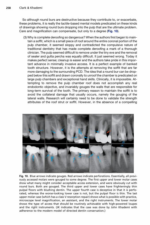
Fig. 10. Blue arrows indicate gouges. Red arrows indicate perforations. Essentially, all previ-ously accessed molars were gouged to some degree. The first upper and lower molar casesshow what many might consider acceptable access extension, and were obviously cut withround burs. Both are gouged. The third upper and lower cases have frighteningly thinpulpal floors with blushing dentin. The upper fourth case is deceptive in that it is perfo-rated, whereas the worse-looking lower case is not, but the pulpal floor is thin. The lastupper molar case (which has a class V resorption repair) shows what is possible with practice,microscope level magnification, an assistant, and the right instruments. The lower molarshows the type of access that should be routinely achievable with high-powered loupesand the right instruments. (JK indicates that the case was done by John Khademi withadherence to the modern model of directed dentin conservation.)
Molar Endodontic Access and Dentin Conservation 259
reason to remove dentin, our default position should always be conservative.This 360� soffit or roof-wall interface can also be compared with the metalring that stabilizes a wooden barrel. Inference to the second moment of inertiain structural engineering deserves analysis. The second potential benefit, asdescribed earlier, is embodied in the physics model of the second moment ofinertia. An ideal example of second moment of inertia is the I beam. The secondmoment or furthest point of the I portion away from the center of the beam, orcentroid, determines the resistance to bending. Maintaining dentin as it roundsa corner places it far from the cervical area, which is often where fracturing initi-ates in the endodontically accessed molar. More important than the soffit itself,however, is the preservation of axial wall dentin near the soffit.
Presuming one could drop into the pulp chamber in the way described earlier (seeFig. 7), the chamber roof is now to be removed by scooping it up and away witha round carbide. A two-dimensional drawing with the small size of the bur andchamber roof overhanging a large pulp chamber makes this seem like a reasonableproposition. The chamber walls are always drawn flat even though they are cut bya round bur.
In practice, it is impossible to cut flat walls in 3 dimensions with a round instrument.The chamber is not unroofed in some areas, leaving pulpal and necrotic debris with nospecific subsequent step to address the debris, yet the walls are overextended andgouged in other areas. Further, the internal radius of curvature at many of the pulpchamber line angles is simply too small for all but the smallest of round burs.
In the final analysis, round burs point cut in an endodontic access application,whereas what is needed is planing. What is needed is a new set of mental modelsbased on vision, and a new set of instruments reflective of the task at hand and thedesired shaping outcomes. The new vision-based mental model is Look, Groom,Follow. The new burs are all round-ended tapers (Fig. 11).
It is appropriate to provide updated cavosurface outlines and cross-sectional illus-trations for initial access for the maxillary and mandibular molars (Table 2).
CAVOSURFACE AND CROSS-SECTIONAL ILLUSTRATIONSFOR MAXILLARY MOLAR ACCESS
Traditional textbooks devote considerable length and effort on drawing access outlineforms that are done on restoration-free, caries-free teeth. The authors hesitate toprovide access outline drawings as there are so many variables that enter into theformula on real clinical cases. Within this context, the authors provide these drawingsas a guideline for accessing full coverage gold or porcelain for cases in which theunderlying restorative materials, the presence or absence of decay, and the locationsof sound dentin cannot be ascertained. When in doubt, a larger outline form throughthe restorative should be cut, but only to the level at which dentin is encountered.Then, the access should be vision based, cuing from the color map and the presenceof any PTRs that can be identified. This method is a stepped access, in which an inten-tionally over-enlarged access is made through the cavosurface of a restored tooth(typically a crowned tooth) to the level at which dentin is encountered, then the accesssteps in to the size of the pulp chamber outline.
The occlusal view drawing shows an inner outline form in black, requiring the mostsophistication in skill and magnification. Suggested extensions for clinicians atdifferent points along the experience/magnification curve in blue and green showextension and enlargement, primarily toward the mesial and buccal. These shouldbe primarily interpreted as the direction to strategically extend the access based on
Fig. 11. Comparison of the CK endodontic access bur with the corresponding round bur. Thetip size of these burs is less than half as wide as the corresponding round bur. One of theprototype CK endodontic access burs (right) is shown and contrasted with the correspond-ing surgical length round bur (left). These burs, designed by Drs Clark and Khademi, will beavailable from SS White Burs, Inc.
Clark & Khademi260
experience/magnification and case difficulty as opposed to absolute outline forms.The angles of entry into the canal system are unlikely to be perpendicular to theocclusal surface. The access rarely needs to be significantly extended to the distalor palatal, as the angle of entry to the palatal canal is out to the mesio-buccal (MB)(Fig. 12), and the distal is toward the mesio-palatal (MP) (Fig. 13). The MB and MB2angles of entry are generally from the distal, and can also be from the palatal (Figs.14 and 15).
Table 2The 6 types of molar cavosurface and chamber access
Restorative Case Type Cavosurface Angle (To Occlusal Table)
Nonmutilated molar to receive bondedindirect onlay or composite onlay
1 mm of anatomic flattening (2 mm cusp tipflattening); then 45� angle of penetrationuntil reaching the dentinal map (Fig. 20)
Nonmutilated molar to receive full crown 1.5 mm of anatomic flattening (2.5 mm cusptip flattening); then 45� angle ofpenetration until reaching the dentin map
Mutilated molar to receive full crown 2–3 mm of flattening
Gold crown to be retained 80� angle of penetration until reaching thedentin map
PFM crown to be retained 45� angle of penetration through the crownuntil reaching the dentin map
Zirconia based porcelain crown* to bemaintained
70–90� angle of penetration until reachingthe dentin map
* As of date of publish, most zirconia based crowns including Lava tm and Procera tm have nonetchable cores and non etchable stacked porcelains.
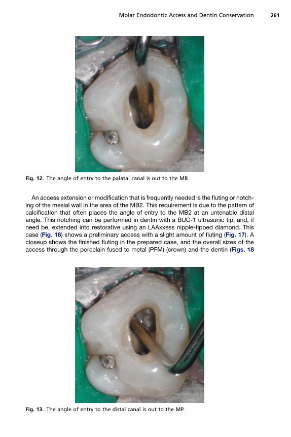
Fig. 12. The angle of entry to the palatal canal is out to the MB.
Molar Endodontic Access and Dentin Conservation 261
An access extension or modification that is frequently needed is the fluting or notch-ing of the mesial wall in the area of the MB2. This requirement is due to the pattern ofcalcification that often places the angle of entry to the MB2 at an untenable distalangle. This notching can be performed in dentin with a BUC-1 ultrasonic tip, and, ifneed be, extended into restorative using an LAAxxess nipple-tipped diamond. Thiscase (Fig. 16) shows a preliminary access with a slight amount of fluting (Fig. 17). Acloseup shows the finished fluting in the prepared case, and the overall sizes of theaccess through the porcelain fused to metal (PFM) (crown) and the dentin (Figs. 18
Fig. 13. The angle of entry to the distal canal is out to the MP.
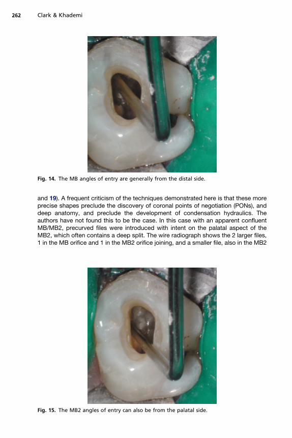
Fig. 14. The MB angles of entry are generally from the distal side.
Clark & Khademi262
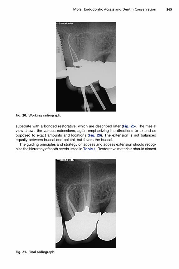
and 19). A frequent criticism of the techniques demonstrated here is that these moreprecise shapes preclude the discovery of coronal points of negotiation (PONs), anddeep anatomy, and preclude the development of condensation hydraulics. Theauthors have not found this to be the case. In this case with an apparent confluentMB/MB2, precurved files were introduced with intent on the palatal aspect of theMB2, which often contains a deep split. The wire radiograph shows the 2 larger files,1 in the MB orifice and 1 in the MB2 orifice joining, and a smaller file, also in the MB2
Fig. 15. The MB2 angles of entry can also be from the palatal side.
Fig. 16. Preoperative condition.
Molar Endodontic Access and Dentin Conservation 263
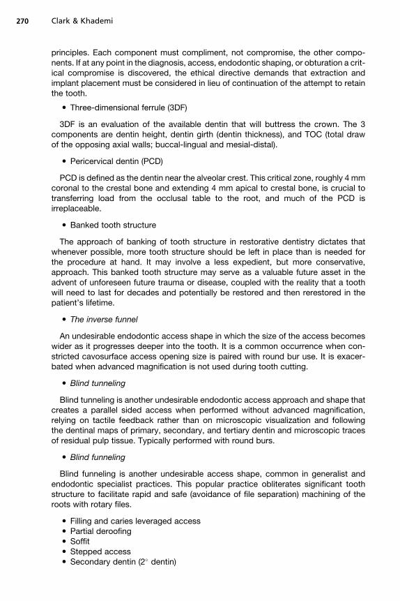
orifice branching deep to a separate portal of exit (Fig. 20). The completed case isshown in Fig. 21.
As discussed earlier, these should be interpreted more as guides on how and whereto extend, rather than as absolute extension guidelines. The first 2 buccal views showa large pulp chamber (Fig. 22), and a raw Clark/Khademi (CK)-style access with small
Fig. 17. Initial access, slight fluting.
Fig. 18. Closeup fluting (arrow).
Clark & Khademi264
soffits of chamber roof left to be debrided later (Fig. 23). The next buccal view is anoverlay of the CK-style access, a more traditional occlusally divergent access, andan access taken from a recent text showing fairly parallel walls, but grossly overex-tended cervically (Fig. 24). The second set of overlays shows the CK-style accesswith blue and green extensions, with cavosurface finish lines appropriate for a bonded
Fig. 19. Access with probe.
Fig. 20. Working radiograph.
Molar Endodontic Access and Dentin Conservation 265
substrate with a bonded restorative, which are described later (Fig. 25). The mesialview shows the various extensions, again emphasizing the directions to extend asopposed to exact amounts and locations (Fig. 26). The extension is not balancedequally between buccal and palatal, but favors the buccal.
The guiding principles and strategy on access and access extension should recog-nize the hierarchy of tooth needs listed in Table 1. Restorative materials should almost
Fig. 21. Final radiograph.
Fig. 22. Buccal view with normal pulp.
Clark & Khademi266
always be sacrificed before tooth structure. More occlusal tooth structure should besacrificed for more cervical tooth structure. The key pericerivcal tooth structure shouldremain as untouched as possible.
Final cavosurface outline extension at the finish appointment (which may be thestart appointment on a 1-step case) hinges on the existing restorative, and the restor-ative plan. If abundant highly bondable substrate such as etchable porcelain or
Fig. 23. Buccal view with CK access and soffit (arrows).
Fig. 24. Buccal view with access overlays.
Molar Endodontic Access and Dentin Conservation 267
enamel is available, and a bondable restorative material such as a heavily filledcomposite resin is planned, the cavosurface should be Cala Lillied (Fig. 27), or gener-ously beveled on those areas. If the bondability of the substrate is of low, or a bondcannot be established between the substrate and restorative material, a butt joint or70 to 90� interface at the cavosurface should be the objective. On multiple visit casesin which an unbonded temporary restoration is placed, the cavosurface should bemaintained at 70 to 90� until the completion visit.
Fig. 25. Buccal view with various extensions.
Fig. 26. Mesial view with various extensions.
Clark & Khademi268
CAVOSURFACE AND CROSS-SECTIONAL ILLUSTRATIONSFOR MANDIBULAR MOLAR ACCESS
These illustrations are consistent with the style of access demonstrated in the maxil-lary molar section earlier (generously flared and flattened when appropriate in thecoronal third of the tooth, then conservative in the middle and apical portion of thecoronal portion of the tooth).
The first step in contemporary molar access in the noncrowned tooth is flattening. Itis a step that is ignored or overdone in most practices.
GUIDELINES FOR TREATMENT DECISIONS
There have been some consistent patterns in what the authors have observed in theirpractices with the long-term successful cases. These observations are important for
Fig. 27. Traditional parallel-sided access (left), compared with the Cala Lilly enamel prepa-ration (right). (Left) Unfavorable C factor and poor enamel rod engagement are typicallypresent when removing old amalgam or composite restorations or with traditionalendodontic access of 90� to the occlusal table. (Right) The enamel is cut back at 45� withthe Cala Lilly shape. This modified preparation will now allow engagement of nearly theentire occlusal surface.
Molar Endodontic Access and Dentin Conservation 269
2 reasons: (1) they can serve to direct how virgin endo/restorative cases planned fortreatment are managed; (2) they can help the endodontist quickly decide whetherretreating failing prior treatment is even worth investigating. Although it would beadvantageous for the treating clinician to have objective randomized clinical trials(RCTs) on the factors related to long-term endodontic success, there is a dearth ofRCTs of longer than 20 years to guide the clinician with the real variables related tolong-term success. The authors are, however, able to observe the cases presentingto their practices. These observations contradict contemporary endodontic thinking,yet, when put to the test, remain essentially unchallenged. They are certain to causecontroversy in the endodontic community:
(1) Long-term, that is, 20- to 40-year, success of the endodontically treated tooth haslittle to do with what would be traditionally characterized as the quality of theendodontic result.
(2) Preservation of dentin trumps quality endodontics when evaluated over a timeframe of 20 to 40 years.
The Three Strikes Rule
In endodontically treated cases from 20 to 40 years ago, the authors have observedconsistently that these teeth are violated in less than 3 ways. The cases that trulygo the distance have damage in 2 or less of the following clinically controllablevariables:
(1) Excessive axial reduction (consistent with PFM or all-porcelain restorations)(2) Gouged endodontic access(3) Large and arbitrarily round endodontic shape.
The authors would contend that teeth that are violated in 3 or more ways simply donot go the distance. All 3 of these violations are insults to the PCD, and if all 3 arepresent, the loss of PCD is irreparable and the tooth is permanently compromisedor destroyed. When the clinician is evaluating a case for possible treatment, it is farmore advantageous and expedient to evaluate the restorative aspects of the case first.One should ask: ‘‘Presuming successful endodontic treatment, what is left to workwith?’’ For instance, if the distal half of the tooth is severely decayed, but the patienthas adequate opening, the access can be distalized, directing dentin conservation tothe mesial half of the tooth, leaving the opportunity for enough 3DF.
With retreatment cases, the rationale is the same, and the question to ask, beforeeven considering the endodontic issues, is: ‘‘How many ways has this tooth beenviolated?’’ If the tooth has been violated 2 or more ways (ie, 3 strikes), it is exception-ally unlikely that a long-term result can be delivered to the patient with even the mostexceptional endodontic care.
GLOSSARY OF TERMS FOR CONTEMPORARY MOLAR ENDODONTIC ACCESS
� The endodontic-endorestorative-prosthodontic (EERP) continuum
The EERP is a restoratively driven view of the endodontics as simply a servant to therestoration and preservation of the tooth, concurrent with a complete integration ofendodontic design as part of an interlocking series of components. From crown toapex an outside fortress of fracture resistance, and from inside to outside a set of fire-walls for leakage prevention. Biomimetics and minimally invasive dentistry are guiding
Clark & Khademi270
principles. Each component must compliment, not compromise, the other compo-nents. If at any point in the diagnosis, access, endodontic shaping, or obturation a crit-ical compromise is discovered, the ethical directive demands that extraction andimplant placement must be considered in lieu of continuation of the attempt to retainthe tooth.
� Three-dimensional ferrule (3DF)
3DF is an evaluation of the available dentin that will buttress the crown. The 3components are dentin height, dentin girth (dentin thickness), and TOC (total drawof the opposing axial walls; buccal-lingual and mesial-distal).
� Pericervical dentin (PCD)
PCD is defined as the dentin near the alveolar crest. This critical zone, roughly 4 mmcoronal to the crestal bone and extending 4 mm apical to crestal bone, is crucial totransferring load from the occlusal table to the root, and much of the PCD isirreplaceable.
� Banked tooth structure
The approach of banking of tooth structure in restorative dentistry dictates thatwhenever possible, more tooth structure should be left in place than is needed forthe procedure at hand. It may involve a less expedient, but more conservative,approach. This banked tooth structure may serve as a valuable future asset in theadvent of unforeseen future trauma or disease, coupled with the reality that a toothwill need to last for decades and potentially be restored and then rerestored in thepatient’s lifetime.
� The inverse funnel
An undesirable endodontic access shape in which the size of the access becomeswider as it progresses deeper into the tooth. It is a common occurrence when con-stricted cavosurface access opening size is paired with round bur use. It is exacer-bated when advanced magnification is not used during tooth cutting.
� Blind tunneling
Blind tunneling is another undesirable endodontic access approach and shape thatcreates a parallel sided access when performed without advanced magnification,relying on tactile feedback rather than on microscopic visualization and followingthe dentinal maps of primary, secondary, and tertiary dentin and microscopic tracesof residual pulp tissue. Typically performed with round burs.
� Blind funneling
Blind funneling is another undesirable access shape, common in generalist andendodontic specialist practices. This popular practice obliterates significant toothstructure to facilitate rapid and safe (avoidance of file separation) machining of theroots with rotary files.
Molar Endodontic Access and Dentin Conservation 271
� Tertiary dentin (3� dentin)� Biomimetic endodontic shaping (BES)� Arbitrary round shaping (ARS)� The dentinal map� The dentinoenamel junction (DEJ)� The junction of primary and secondary dentin (D2J)� The junction of primary and tertiary dentin (D3J)� Pulp tissue remnants (PTRs)� The Cala Lilly
Fig. 27 highlights the creation of the Cala Lilly cavity shape. The Cala Lilly is a flowerand is the new model for composite preparations.
� Points of negotiation (PONs)
PONs are statistically predictable anatomic areas that may serve as starting pointsduring the access portion of endodontic therapy.
Italicized points indicate an undesirable outcome or technique.
ACKNOWLEDGMENTS
Dr Clark would like to thank Dr Jihyon Kim, Dr Eric Herbransen and Dr Marc Balson,for their input and unwavering support.
REFERENCES
1. Tay FR, Pashley DH. Monoblocks in root canals: a hypothetical or a tangible goal.J Endod 2007;33(4):391–8.
2. Wahl MJ, Schmitt MM, Overton DA, et al. Prevalence of cusp fractures in teethrestored with amalgam and with resin-based composite. J Am Dent Assoc2004;135:1127–32.
3. Schwartz RS, Robbins JW. Post placement and restoration of endodonticallytreated teeth: a literature review. J Endod 2004;30(5):289–301.
4. Lirtchirakarn V. Patterns of vertical root fractures: factors affecting stress distribu-tion in the root canal. J Endod 2003;29:523–8.
5. Tamse A. An evaluation of endodontically treated vertically fractured teeth. J En-dod 1999;25:506–8.
6. Miles B. Sales data. New Jersey: SS White Bur Inc; 2008.7. Tan PL, Aquilino SA, Gratton DG, et al. In vitro fracture resistance of endodonti-
cally treated central incisors with varying ferrule heights and configurations.J Prosthet Dent 2005;93(4):331–6.
8. Sahafi A, Peutzfeldt A, Ravnholt G, et al. Resistance to cyclic loading of teethrestored with posts. Clin Oral Investig 2005;9(2):84–90.
9. Kutesa-Mutebi A, Osman YI. Effect of the ferrule on fracture resistance of teethrestored with prefabricated posts and composite cores. Afr Health Sci 2004;4(2):131–5.
10. Akkayan B. An in vitro study evaluating the effect of ferrule length on fractureresistance of endodontically treated teeth restored with fiber-reinforced andzirconia dowel systems. J Prosthet Dent 2004;92(2):155–62.
11. Goto Y, Nicholls JI, Phillips KM, et al. Fatigue resistance of endodontically treatedteeth restored with three dowel-and-core systems. J Prosthet Dent 2005;93(1):45–50.
Clark & Khademi272
12. Ng CC, al-Bayat MI, Dumbrigue HB, et al. Effect of no ferrule on failure of teethrestored with bonded posts and cores. Gen Dent 2004;52(2):143–6.
13. Smidt A, Venezia E. The use of an existing cast post and core as an anchor forextrusive movement. Int J Prosthodont 2003;16(3):225–8.
14. Pierrisnard L, Bohin F, Renault P, et al. Corono-radicular reconstruction of pulp-less teeth: a mechanical study using finite element analysis. J Prosthet Dent2002;88(4):442–8.
15. Stankiewicz NR, Wilson PR. The ferrule effect: a literature review. Int Endod J2002;35(7):575–81. Review.
16. Hsu YB, Nicholls JI, Phillips KM, et al. Effect of core bonding on fatigue failure ofcompromised teeth. Int J Prosthodont 2002;15(2):175–8.
18. al-Hazaimeh N, Gutteridge DL. An in vitro study into the effect of the ferrule prep-aration on the fracture resistance of crowned teeth incorporating prefabricatedpost and composite core restorations. Int Endod J 2001;34(1):40–6.
19. Gegauff AG. Effect of crown lengthening and ferrule placement on static load failureof cemented cast post-cores and crowns. J Prosthet Dent 2000;84(2):169–79.
20. Morgano SM, Brackett SE. Foundation restorations in fixed prosthodontics:current knowledge and future needs [review]. J Prosthet Dent 1999;82(6):643–57.
21. Hunter AJ, Hunter AR. The treatment of endodontically treated teeth. Curr OpinDent 1991;1(2):199–205. Review.
22. Loney RW, Kotowicz WE, McDowell GC. Three-dimensional photoelastic stressanalysis of the ferrule effect in cast post and cores. J Prosthet Dent 1990;63(5):506–12.
23. Jorgensen KD. The relationship between retention and convergence angle in ce-mented veneer crowns. Acta Odontol Scand 1955;13:35–40.
24. Wilson AH, Chan DC. The relationship between preparation convergence andretention of extracoronal retainers. J Prosthodont 1994;3:74–8.
25. Smith CT, Gary JJ, Conkin JE, et al. Effective taper criterion for the full veneercrown preparation in preclinical prosthondontics. J Prosthodont 1999;8:196–200.
26. Noonan JE Jr, Goldfogel MH. Convergence of the axial walls of full veneer crownpreparations in a dental school environment. J Prosthet Dent 1991;66:706–8.
27. Ohm E, Silness J. The convergence angle in teeth prepared for artificial crowns.J Oral Rehabil 1978;5:371–5.
28. Annerstedt A, Engstrom U, Hansson A, et al. Axial wall convergence of full veneercrown preparations. Documented for dental students and general practitioners.Acta Odontal Scand 1996;54:109–12.
29. Lempoel PJ, Snoek PA, van’t Hof M, et al. [The convergence angel of crown prep-arations with clinically satisfactory retention]. Ned Tijdschr Tandheelkd 1993;100:336–8 [in Dutch].
30. Mou SH, Chai T, Wang JS, et al. Influence of different convergence angles andtooth preparation heights on the internal adaptation of Cerec crowns. J ProsthetDent 2002;87:248–55.
31. Dodge WW, Weed RM, Baez RJ, et al. The effect of convergence angle on reten-tion and resistance form. Quintessence Int 1985;16:191–4.
32. Shillingburg HT, Hobo S, Whitset LD, et al. Fundamentals of fixed prosthodontics.3rd edition. Chicago: Quintessence; 1997.
33. Wiskott HW, Nicholls JI, Belser UC. The relationship between abutment taper andresistance of cemented crowns to dynamic loading. Int J Prosthodont 1996;9:117–39.
Molar Endodontic Access and Dentin Conservation 273
34. Trier AC, Parker MH, Cameron SM, et al. Evaluation of resistance form of dis-lodged crowns and retainers. J Prosthet Dent 1998;80:405–9.
35. Maxwell AW, Blank LW, Pelleu GB Jr. Effect of crown preparation height on theretention and resistance of gold castings. Gen Dent 1990;38:200–2.
36. Park MH, Calverley MJ, Gardner FM, et al. New guidelines for preparation taper.J Prosthodont 1993;2:61–6.
37. Woolsey GD, Matich JA. The effect of axial grooves on the resistance form of castrestorations. J Am Dent Assoc 1978;97:978–80.