45
Modern Optics II – Polarization of light Special topics course in IAMS Lecture speaker: Wang-Yau Cheng 2006/4
| Date post: | 28-Dec-2015 |
| Category: |
Documents |
| Upload: | emery-dalton |
| View: | 221 times |
| Download: | 0 times |
Modern Optics II – Polarization of light
Special topics course in IAMS
Lecture speaker: Wang-Yau Cheng
2006/4
Outline
• Wave properties of light
• Polarization of light
• Coherence of light
• Special issues on quantum optics
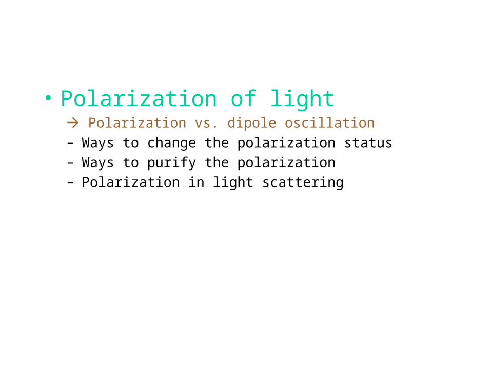
• Polarization of light Polarization vs. dipole oscillation
– Ways to change the polarization status
– Ways to purify the polarization
– Polarization in light scattering
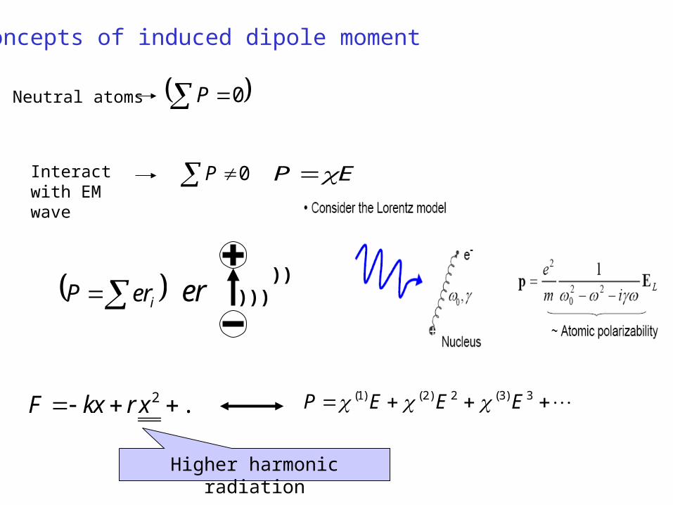
Concepts of induced dipole moment
0P
EP
ireP
re ))))))
3)3(2)2()1( EEEP ...2 xrxkF
Higher harmonic radiation
0P
Neutral atoms
Interact with EM wave
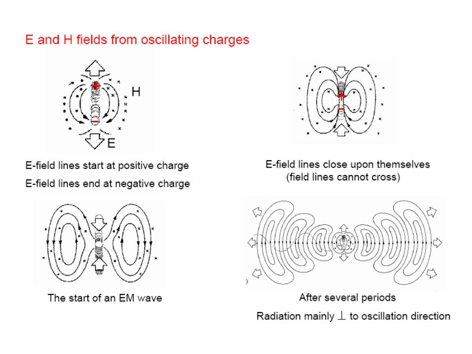
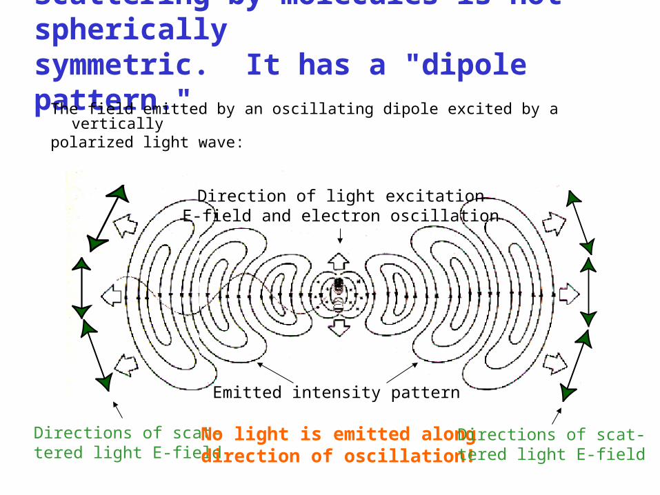
Scattering by molecules is not sphericallysymmetric. It has a "dipole pattern."
The field emitted by an oscillating dipole excited by a verticallypolarized light wave:
Directions of scat-tered light E-field
No light is emitted alongdirection of oscillation!
Directions of scat-tered light E-field
Direction of light excitationE-field and electron oscillation
Emitted intensity pattern

Dipole Emission Pattern from an Antenna
The pattern is somewhat distorted by the earth and nearby objects.
Analogous to a molecule emitting light, an antenna emits a dipole pattern at much lower frequency and longer wavelength:
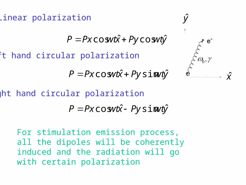
Linear polarization
ywtPyxwtPxP ˆcosˆcos
Left hand circular polarization
Right hand circular polarization
ywtPyxwtPxP ˆsinˆcos
ywtPyxwtPxP ˆsinˆcos
For stimulation emission process, all the dipoles will be coherently induced and the radiation will go with certain polarization
y
x
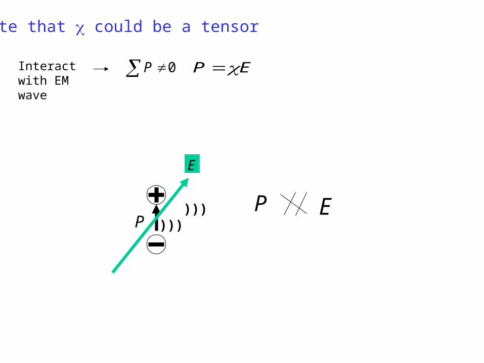
Note that could be a tensor
0P
EP
Interact with EM wave
))))))P
E
E
P

Optical Activity
Unlike birefringence, optical activity maintains a linear polarization
throughout. The rotation angle is proportional to the distance.
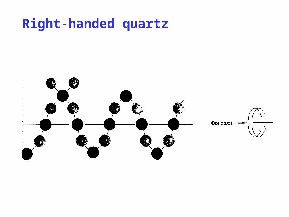
Right-handed quartz

• Polarization of light– Polarization vs. dipole oscillation
Ways to change the polarization status
– Ways to purify the polarization
– Polarization in light scattering

Wave platesWhen a beam propagates through a birefringent medium, onepolarization experiences more phase delay than the other.
If both polarizations are present, this has the effect of changingrelative phase of the x and y fields, and hence rotating the polarization.
Input:Polarization state:
~ 0
~ 0
~ 0
~ 0
( , ) Re exp
( , ) Re exp
( , ) Re exp
( , ) Re exp
x
y
x o
y e
E z t E i kz t
E z t E i kz t
E z t E i kz kn d t
E z t E i kz kn d t
1
1
exp( )
exp( )
1
2exp
o
e
o e
ikn d
ikn d
i n n d
Output:
}
}
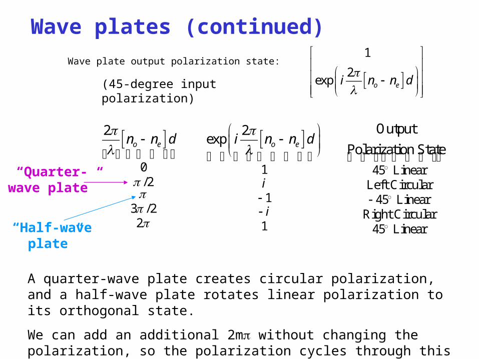
Wave plates (continued)
Wave plate output polarization state:
1
2exp o ei n n d
0 1 45 Linear/2 Left Circular
1 45 Linear3 /2 Right Circular2 1 45 Linear
Output2 2 exp
Polarization Stateo e o e
i
i
n n d i n n d
A quarter-wave plate creates circular polarization, and a half-wave plate rotates linear polarization to its orthogonal state.
We can add an additional 2m without changing the polarization, so the polarization cycles through this evolution as d increases further.
“Quarter-wave plate”
“Half-wave plate”
(45-degree input polarization)

Half-Wave Plate
If the incident polarization is 45° to the principal axes, then theoutput polarization is rotated by 90°.
If the incident polarization is parallel to one of the principal axes of the plate, then no polarization rotation occurs.
When a beam propagates through a half-wave plate, one polarizationexperiences half of a wavelength more phase delay than the other.

Jones Matrices for standard components
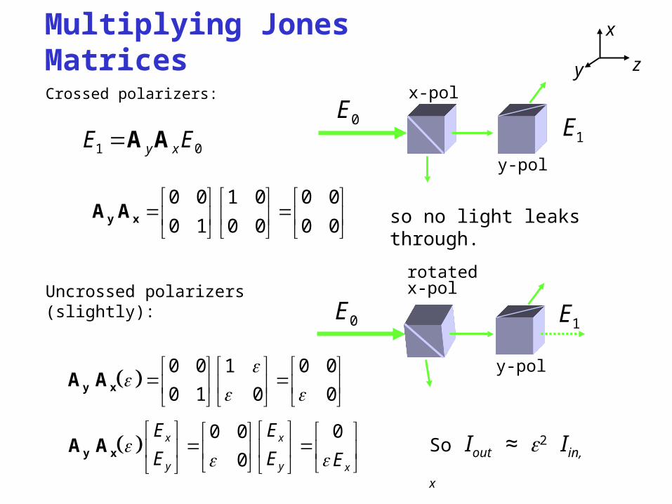
Multiplying Jones Matrices
Crossed polarizers:
0 0 1 0 0 0
0 1 0 0 0 0
y xA A
x
y z
1 0y xE EA A0E
1E
x-pol
y-pol
so no light leaks through.
Uncrossed polarizers(slightly):
0 0 1 0 0
0 1 0 0
y xA A
0E1E
rotatedx-pol
y-pol
00 0
0x x
y y x
E E
E E E
y xA A So Iout ≈2 Iin,x
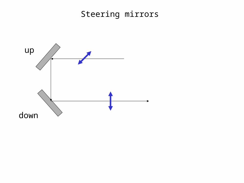
up
down
Steering mirrors

CRYSTAL QUARTZ WAVEPLATES
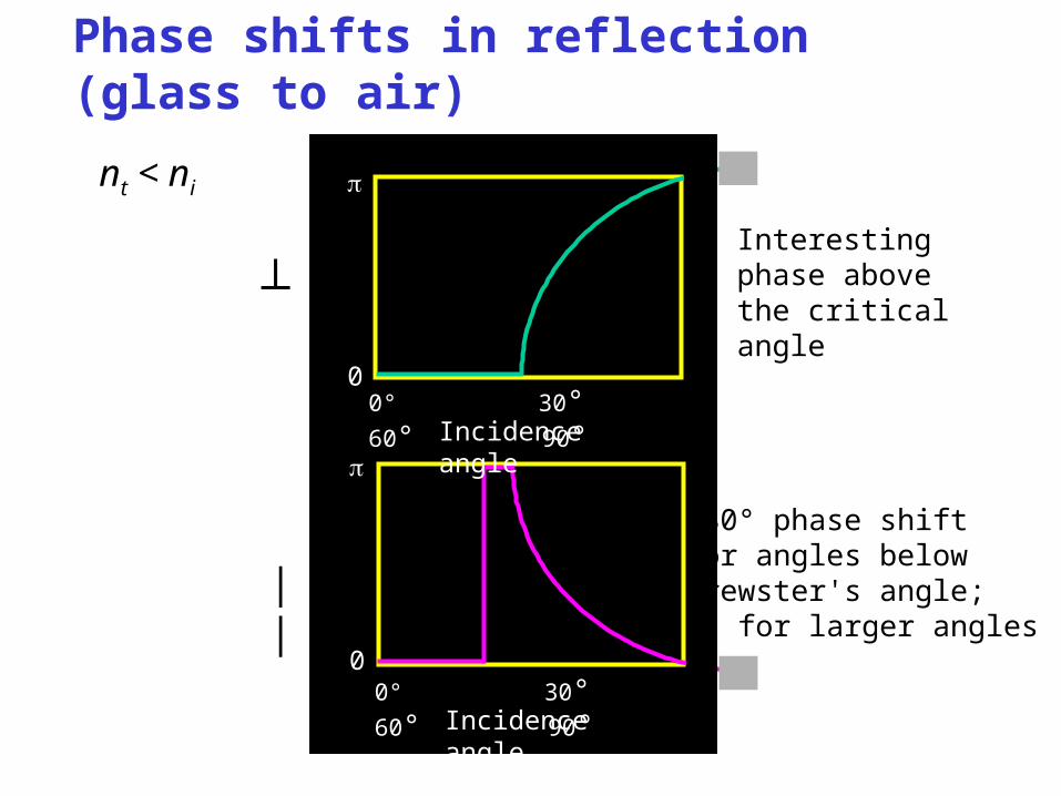
Phase shifts in reflection (glass to air)
nt < ni
Interesting phase above the critical angle
180° phase shiftfor angles belowBrewster's angle;0° for larger angles
0° 30° 60° 90°Incidence angle
0° 30° 60° 90°Incidence angle
0
0
┴
||
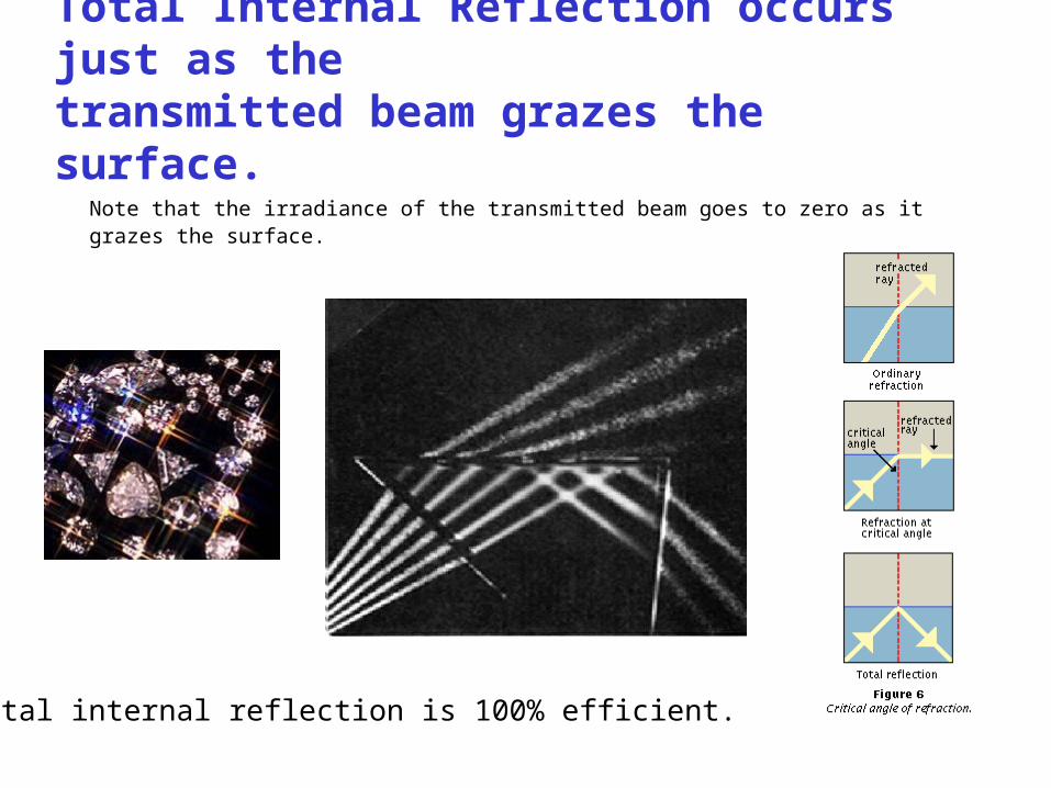
Total Internal Reflection occurs just as thetransmitted beam grazes the surface.
Note that the irradiance of the transmitted beam goes to zero as itgrazes the surface.
Total internal reflection is 100% efficient.
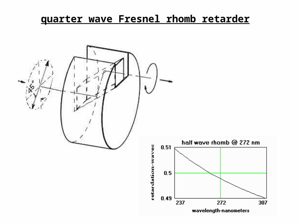
quarter wave Fresnel rhomb retarder
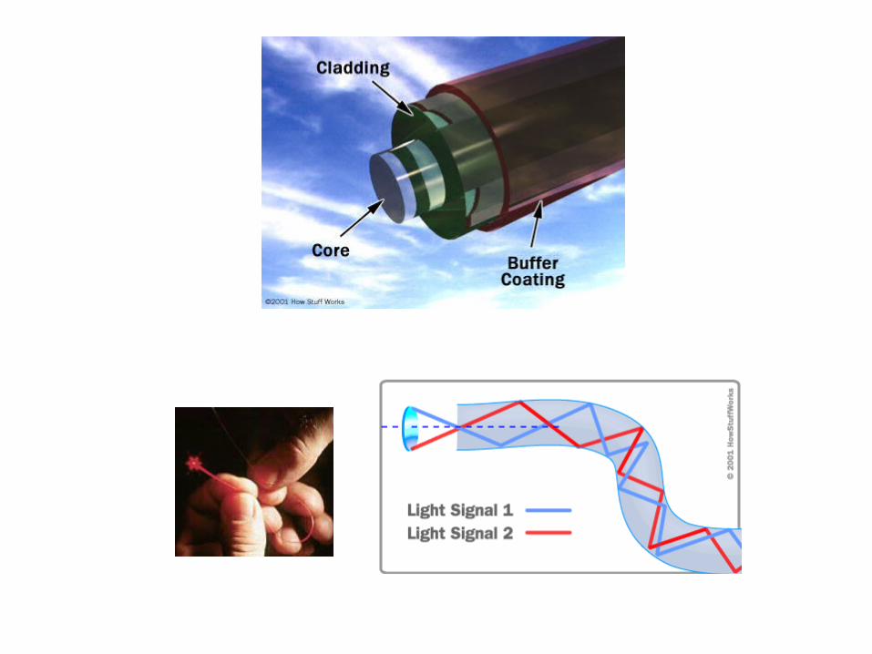
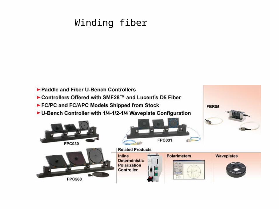
Winding fiber

The Faraday Effect
A magnetic field can induce optical activity.
The Faraday effect allows control over the polarization rotation.
• Polarization of light– Polarization vs. dipole oscillation
– Ways to change the polarization status
Ways to purify the polarization
– Polarization in light scattering

Phase shifts in reflection (air to glass)
ni < nt
180° phase shiftfor all angles
180° phase shiftfor angles belowBrewster's angle;0° for larger angles
0° 30° 60° 90°Incidence angle
0° 30° 60° 90°Incidence angle
0
0
┴
||

Phase shifts in reflection (glass to air)
nt < ni
Interesting phase above the critical angle
180° phase shiftfor angles belowBrewster's angle;0° for larger angles
0° 30° 60° 90°Incidence angle
0° 30° 60° 90°Incidence angle
0
0
┴
||
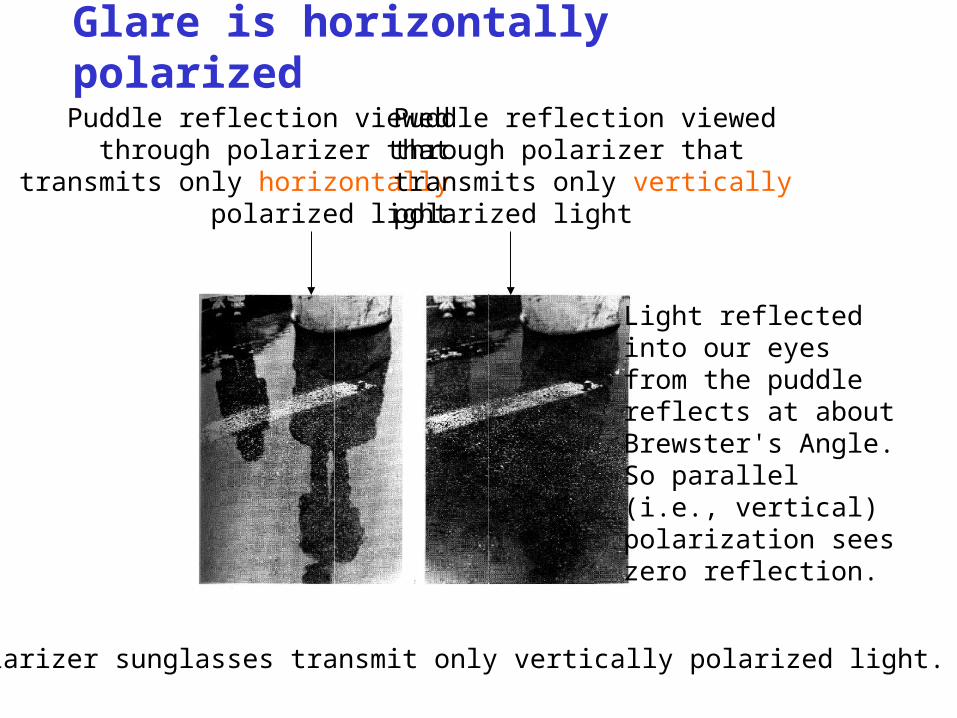
Glare is horizontally polarized
Puddle reflection viewedthrough polarizer that
transmits only horizontallypolarized light
Puddle reflection viewedthrough polarizer thattransmits only verticallypolarized light
Light reflectedinto our eyesfrom the puddlereflects at about Brewster's Angle.So parallel(i.e., vertical)polarization seeszero reflection.
Polarizer sunglasses transmit only vertically polarized light.
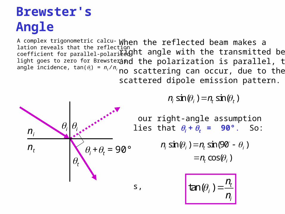
When the reflected beam makes aright angle with the transmitted beam,and the polarization is parallel, then no scattering can occur, due to the scattered dipole emission pattern.
But our right-angle assumption implies that i + t = 90°. So:
Thus,
Brewster's Angle
A complex trigonometric calcu-lation reveals that the reflectioncoefficient for parallel-polarizedlight goes to zero for Brewster'sangle incidence, tan(i) = nt / ni
sin( ) sin( )i i t tn n
sin( ) sin(90 )
cos( )i i t i
t i
n n
n
tan( ) ti
i
n
n
ni
nt
i i
t
i +t = 90°
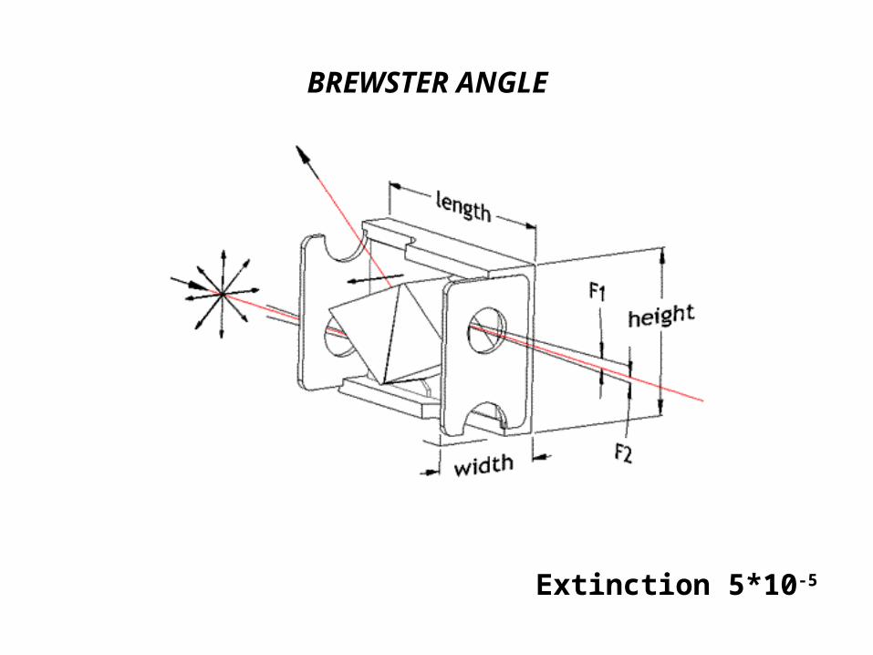
BREWSTER ANGLE
Extinction 5*10-5
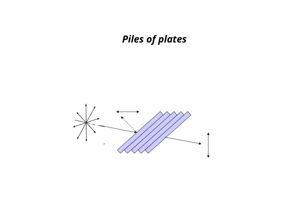
Piles of plates

The extinction of transmitted -p component is at least 1 part in 500
BROAD BAND POLARIZING CUBES

GLAN THOMPSON
The Glan Thompson polarizer is made of two calcite prisms cemented together. Two types of Glan Thompsons are available. One is the standard form and the other is the long form. Their length to aperture ratios are 2.5 : 1 and 3.0 : 1 respectively. Glan Thompsons tend to have higher extinction ratio than air spaced polarizers. In the ultra violet spectrum, their transmission is limited by absorption in calcite as well as the cement layer. These polarizers can be used from about 350 to 2300 nm.
Extinction 5*10-5

GLAN TAYLOR
The Glan Taylor prism polarizer is made of two calcite prisms which are assembled with an air space . It has a length to aperture ratio of approximately 1.0 which makes it a relatively thin polarizer. It is made of UV selected calcite. A 10 mm thick calcite plate having 50% or more transmission at 250 nm is considered UV selected. The spectral range of this polarizer is from 250-2300 nm. Below 250 nm, transmission cutoff wavelength varies from crystal to crystal.
Extinction 1*10-4
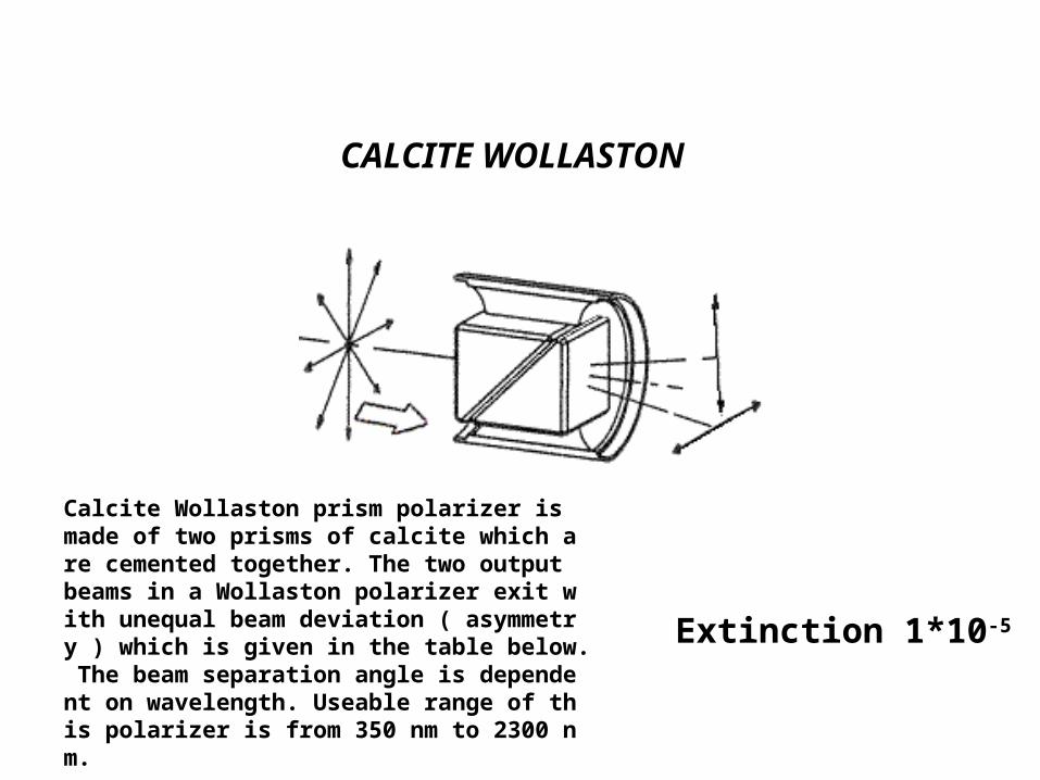
CALCITE WOLLASTON
Calcite Wollaston prism polarizer is made of two prisms of calcite which are cemented together. The two output beams in a Wollaston polarizer exit with unequal beam deviation ( asymmetry ) which is given in the table below. The beam separation angle is dependent on wavelength. Useable range of this polarizer is from 350 nm to 2300 nm.
Extinction 1*10-5

MAGNESIUM FLUORIDE ROCHON
The magnesium fluoride Rochon polarizer is made of two prisms of single crystal magnesium fluoride which are optically contacted. This polarizer can be used over the spectral range of 140 to 6000 nm and has an extinction ratio of at least 10-3.
extinction ratio of at least 10-3
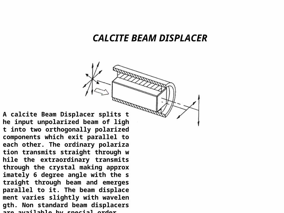
CALCITE BEAM DISPLACER
A calcite Beam Displacer splits the input unpolarized beam of light into two orthogonally polarized components which exit parallel to each other. The ordinary polarization transmits straight through while the extraordinary transmits through the crystal making approximately 6 degree angle with the straight through beam and emerges parallel to it. The beam displacement varies slightly with wavelength. Non standard beam displacers are available by special order.

Polarizer used in camera
The extinction of transmitted -p component is at least 1 part in 200
• Polarization of light– Polarization vs. dipole oscillation
– Ways to change the polarization status
– Ways to purify the polarization
Polarization in light scattering
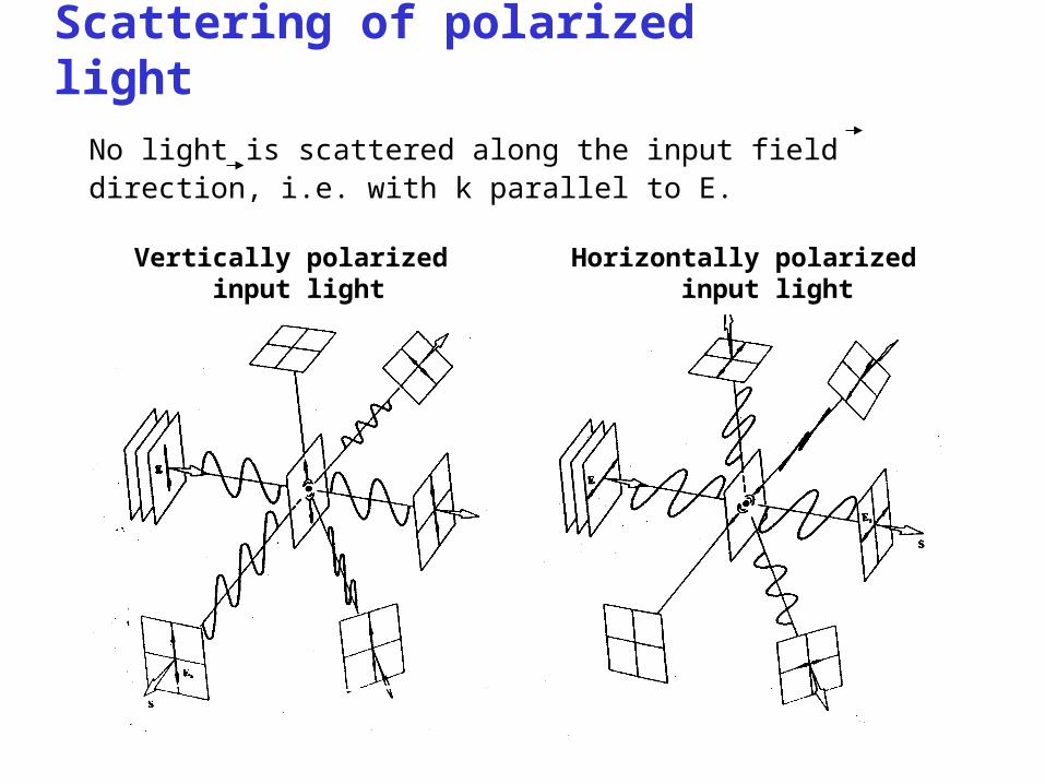
Scattering of polarized light
No light is scattered along the input field direction, i.e. with k parallel to E.
Vertically polarized input light
Horizontally polarized input light

Scattering of unpolarized light
Again, no light is scattered along the input field direction,
i.e. with k parallel to Einput.

Scattering in the Earth's atmosphere leads to interesting polarization properties of skylight.
Sun's rays

Skylight is polarized if the sun is to your side.
Right-angle scattering is polarized
Polarizer transmitting vertical polarization
Multiple scattering yields some light of the other polarization.In clouds, much multiple scattering occurs, and light there is unpolarized.
This polarizer transmits horizontal polarization (of which there is very little).
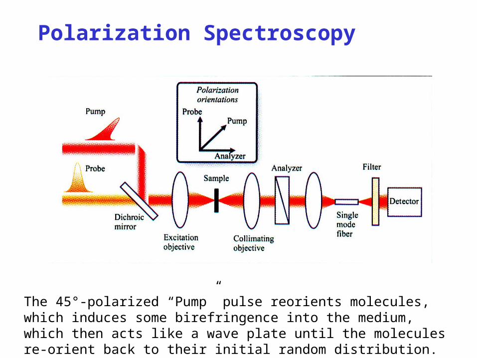
Polarization Spectroscopy
The 45°-polarized “Pump” pulse reorients molecules, which induces some birefringence into the medium, which then acts like a wave plate until the molecules re-orient back to their initial random distribution.


