JULY 2008 MODERN STEEL CONSTRUCTION 31 T Hollow steel castings help bring an exposed structural steel “tree” to life on a Canadian university campus. Branching BY TERRI MEYER BOAKE TUBE-TO-TUBE CONNECTIONS, PARTICULARLY INVOLVING ROUND SECTIONS, ARE A POPULAR CHOICE WITH DESIGNERS. From the architect’s perspec- tive, round sections are desirable because of their clean appear- ance and their indifference to apparent orientation. Engineers like tubular members (HSS and steel pipe sections) for their efficiency; tubular structures provide a higher strength-to-weight ratio than wide-flange sections. And then there are the cost savings, thanks to a reduced surface area for paint or intumescent coatings. Typically, when round sections have been selected, the inference is “Architecturally Exposed Structural Steel”. But for all its benefits, this designation carries a complete set of additional baggage insofar as detailing, fabrication, erection, and finishing are concerned. Fabricators must come up with connection details that are as clean and potentially seamless as envisioned by the architect; pro- vide the strength and efficiency expected by the engineer; meet AESS requirements; and are able to be fabricated and erected in an economical manner. Thankfully, fabrication methods have progressed significantly due to advances in computer numeric control (CNC) processes. But even if complex tube-to-tube connections can be made more accurately and more cleanly, they still exhibit geometric character- istics that may be too overwrought in appearance for some archi- tectural applications. Steel castings, however, can be used to solve complex tube- to-tube geometries while providing a solution that is potentially both technically and aesthetically superior. The use of castings to connect round tubular members is by no means new. But where numerous European buildings have employed castings, North American applications are rare. Planting the Acorn Because research institutions are known for helping to craft the future, perhaps it’s fitting that one of the earliest casting applica- tions on this continent is at a university. Phase one of the Univer- sity of Guelph Science Complex in Guelph, Ontario, Canada is a 350,000-sq.-ft building with a triangular-shaped connecting atrium at its center, the focal point of which is a steel “tree” structure. En- visioning supporting structures as trees has its origins in the designs and load transfer mechanisms of Gothic cathedrals, which use com- pression to direct the forces through the stone pieces and into the foundations. In the case of the Science Complex atrium, the tree structure was to be fabricated from round tubular steel sections, prompting it to act more like a space frame. The upper branches of HSS projects Terri Meyer Boake Out
Transcript
JULY 2008 MODERN STEEL CONSTRUCTION 31
THollow steel castings help bring an exposed structural steel
“tree” to life on a Canadian university campus.
BranchingBY TERRI MEYER BOAKE
TUBE-TO-TUBE CONNECTIONS, PARTICULARLY INVOLVING ROUND SECTIONS, ARE A POPULAR CHOICE WITH DESIGNERS. From the architect’s perspec-tive, round sections are desirable because of their clean appear-ance and their indifference to apparent orientation. Engineers like tubular members (HSS and steel pipe sections) for their effi ciency; tubular structures provide a higher strength-to-weight ratio than wide-fl ange sections. And then there are the cost savings, thanks to a reduced surface area for paint or intumescent coatings.
Typically, when round sections have been selected, the inference is “Architecturally Exposed Structural Steel”. But for all its benefi ts, this designation carries a complete set of additional baggage insofar as detailing, fabrication, erection, and fi nishing are concerned.
Fabricators must come up with connection details that are as clean and potentially seamless as envisioned by the architect; pro-vide the strength and effi ciency expected by the engineer; meet AESS requirements; and are able to be fabricated and erected in an economical manner.
Thankfully, fabrication methods have progressed signifi cantly due to advances in computer numeric control (CNC) processes. But even if complex tube-to-tube connections can be made more accurately and more cleanly, they still exhibit geometric character-
istics that may be too overwrought in appearance for some archi-tectural applications.
Steel castings, however, can be used to solve complex tube-to-tube geometries while providing a solution that is potentially both technically and aesthetically superior. The use of castings to connect round tubular members is by no means new. But where numerous European buildings have employed castings, North American applications are rare.
Planting the AcornBecause research institutions are known for helping to craft the
future, perhaps it’s fi tting that one of the earliest casting applica-tions on this continent is at a university. Phase one of the Univer-sity of Guelph Science Complex in Guelph, Ontario, Canada is a 350,000-sq.-ft building with a triangular-shaped connecting atrium at its center, the focal point of which is a steel “tree” structure. En-visioning supporting structures as trees has its origins in the designs and load transfer mechanisms of Gothic cathedrals, which use com-pression to direct the forces through the stone pieces and into the foundations. In the case of the Science Complex atrium, the tree structure was to be fabricated from round tubular steel sections, prompting it to act more like a space frame. The upper branches of
HSS projects
Terri Meyer Boake
Out
the tree carry the loads from the grid-like wide-fl ange framing system that supports the atrium roof, down through its tubular trunk to the concrete foundation below. This type of geometry, in its tree-like stretch, creates large eccentric forces that put signif-icant moment stresses into the nodes con-necting the branches.
The design of the nodes fl owed from the architect’s vision to create the tree-like exterior geometry. The wall thicknesses of the connectors were optimized to be both safe and economical, and the castings were determined to have superior performance characteristics if cast hollow (solid castings are sometimes preferred in seismic zones). It was deemed essential that if tested to fail-ure, the node should be stronger than the tubular branches. In testing the node, short sections of pipe were added to the casting to simulate more closely the effect that the connection and transfer of the load to the branches would have on the material stresses.
Cast steel exhibits isotropic properties, making it quite suitable, in the case of these extremely eccentrically loaded nodes, for transferring forces through the connection in a reliable manner—i.e., being able to re-sist shear, moment, and torsional stresses. It accomplishes this by working the geometry as a function of variations in the wall thick-ness, independently of the fi nished form of the exterior. Unlike fabrications made from tubes or plates, the interior dimensions of the void in a casting do not have to match the exterior form of the object.
The steel specifi ed for the tree casting had to meet ASTM A27 Grade 70/40, with a modifi ed chemistry to ensure that it could be welded to the pipe branch with minimal preheating and would require no post-weld heat treatment (stress relieving). Although the casting would be shop welded and fi nished to one end of each branch/trunk, site welding would be required for the opposite end.
While site conditions would make both pre- and post-heating diffi cult, weldability was improved by specifying a lower car-bon and silicon content, eliminating the need for preheating. The casting steel’s minimum yield strength was to be 275 MPa. Instead of using regular HSS sec-tions, pipe was selected for the project due to properties that were more closely aligned with those of the casting.
The key requirements included in the bid for the node fabrication included:
Walters, Inc.
The castings are prepped for connection to the tubes at Walters, Inc.’s fabrication shop (left). A top view of the casting, showing the beveled edge, collar, and alignment guide plates (right).
Terri Meyer Boake
JULY 2008 MODERN STEEL CONSTRUCTION 33
the addition of a sleeve, inserted inside the casting, as well as paired plates, also inside the casting, that would help gravity-guide the branch pipe sections into proper alignment during erection. Because the fi nal fi nish on the members was to be high-gloss, great care was taken not to damage the members during erection. Canvas slings were used for lifting, and pads were placed in the V-shaped rests for the branches to ensure against damage. The fabrication of the end connectors was performed to a high level of precision, with all marks and welds being ground completely smooth prior to priming.
Ostensibly SeamlessWhat makes the fi nal resolution of this
particular project, and its tube-to-casting connections, unique is the way in which the transition between the elements was made to appear completely seamless. Multiple passes of welding were used to completely fi ll the V-shaped gap in the connection between the pipe and casting. This was subsequently ground completely smooth, prior to accept-ing the fi nal fi nish. The extra effort to detail and fabricate this connection speaks for itself, as the resulting structure exhibits an elegance and lightness that uses this combination of HSS and castings to the best advantage.
Terri Meyer Boake is the Associate Director and an associate professor of the School of Ar-chitecture, University of Waterloo, Waterloo, Ontario, Canada.
OwnerUniversity of Guelph, Guelph, Ontario, Canada
ArchitectYoung+Wright, Toronto
Structural EngineerCarruthers and Wallace, Toronto
Steel Fabricator and ErectorWalters, Inc., Hamilton, Ontario, Canada
wide-fl ange roof beam grid. The project included fi ve castings to resolve the vari-ous branching conditions. The main cast-ing weighed about 1,080 kg (2,381 lb) and measured about 900 mm (3 ft) in height and 1,200 mm (4 ft) across. Its wall thick-ness varies but is in the range of 65 mm (2.55 in.). The secondary set of four castings that branch into three or four limbs weighed about 500 kg (1,102 lb), were 640 mm (2 ft) tall and 1,000 mm (3.3 ft) wide, and had a wall thickness of about 40 mm (1.6 in.).
A cage of temporary steel was erected around the base column to provide support for the branches as they were erected. Un-til the welding of the pipe-to-casting was complete, the branches could not be self-supporting. The temporary support frame-work also provided shoring for the wide-fl ange roof grid. This construction sequence was necessary in order to allow the upper branches to be erected last and to allow the slotted hinge connections to slide easily into the mates already in place on the underside of the wide-fl ange sections.
The pipe-to-casting connection relied on
• Patterning, heat dissipation analysis, stress relieving, and all other activities inherent to the steel casting process.
• Surface fi nish comparable to that of the seamless steel pipe to which it would be attached. This was crucial to achieving an AESS 4 Category in terms of the ultimate high-gloss surface fi nish to be applied. (For more on Canadian AESS requirements, see “A Categorical Approach,” 04/08, p. 43.)
• Non-destructive evaluation of each casting, including 100% ultrasonic testing as a minimum. Acceptance criteria to be as per CSA W59 Clause 11.
• Dimensional verifi cation that the casting and machining complies to the drawings, with tolerances of +/- 3 mm (0.12 in.) on diameter of cast surface.
Growing the TreeThe erection of the tree began with its
“trunk,” which included a series of welded plates that created a fl are at the base, in-creasing its diameter and connection to the foundation. The 610-mm-diameter (24-in.) steel pipe trunk branches initially into four 406-mm-diameter (16-in.) seamless steel pipe branches via the main casting. These in turn branch through the secondary cast-ings to form fourteen 273-mm-diameter (8-in.) branches—two sets in clusters of three and four branches. Each of the up-per 14 branches terminates in a hinge connector, where each supports the steel
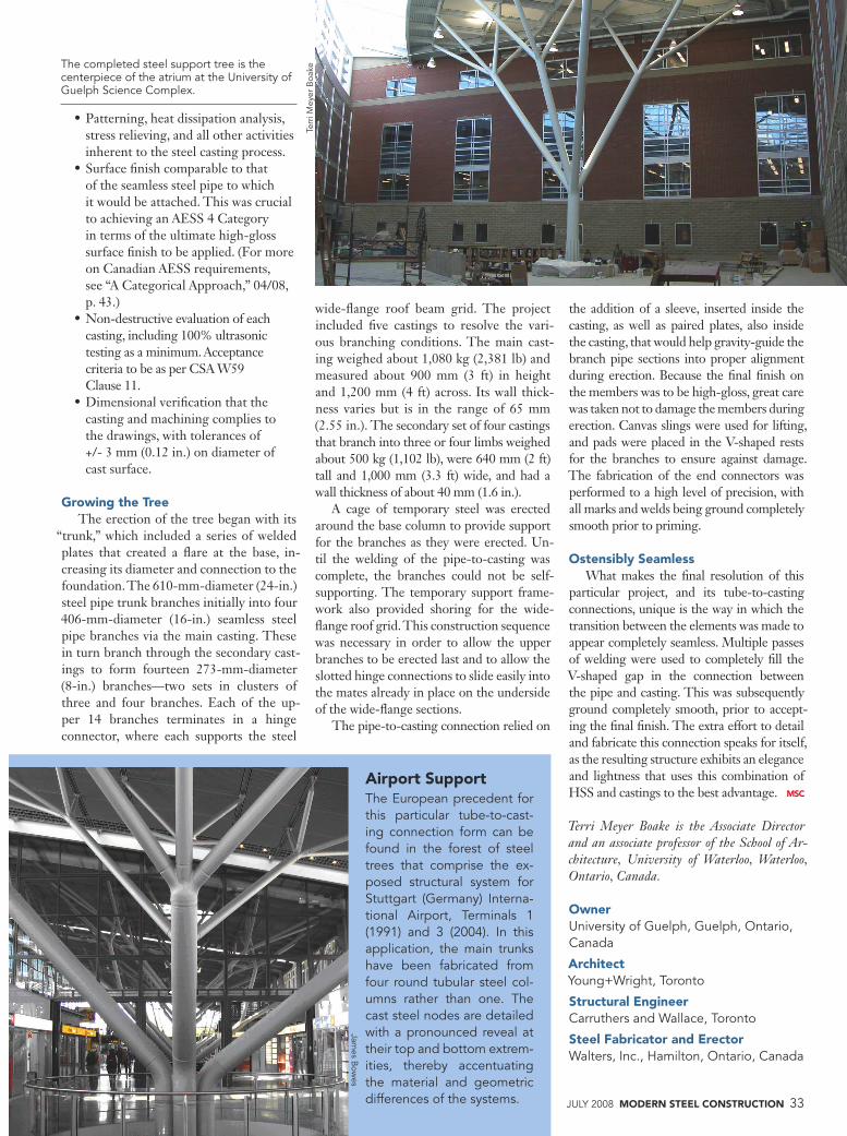
The completed steel support tree is the centerpiece of the atrium at the University of Guelph Science Complex.
Terr
i Mey
er B
oake
Airport SupportThe European precedent for this particular tube-to-cast-ing connection form can be found in the forest of steel trees that comprise the ex-posed structural system for Stuttgart (Germany) Interna-tional Airport, Terminals 1 (1991) and 3 (2004). In this application, the main trunks have been fabricated from four round tubular steel col-umns rather than one. The cast steel nodes are detailed with a pronounced reveal at their top and bottom extrem-ities, thereby accentuating the material and geometric differences of the systems.