19 TH SYMPOSIUM OF THE INDUSTRIAL APPLICATION OF GAS TURBINES COMMITTEE BANFF, ALBERTA, CANADA OCTOBER 17-19, 2011 The IAGT Committee is sponsored by the Canadian Gas Association and supported by the National Research Council Canada. The IAGT Committee is not responsible for statements or opinions advanced in the technical papers or at the Symposium or meeting discussions. Abstract DCP Midstream has recently upgraded the turbine and compressor control systems at their Goldsmith Texas Gas processing plant. These upgrades included replacing the original OEM controls on two GE LM2500 turbines, and two Demag/Delaval 4 section centrifugal compressors to increase reliability, efficiency, simplify operation and streamline maintenance and support requirements. This paper describes the process used to qualify the need to modernize the controls replacement control systems assessment, and the turnkey vendor evaluation and selection. Project scope development, implementation, results and benefits derived from the system upgrades are also discussed. The plant downtime for the whole project was minimized to 10 days and this included the successful commissioning of the plant that was completed in April 2011. The project significantly improved the overall plant availability and reliability. 11-IAGT-XXX (REFERENCE PROGRAM) MODERNIZING TURBO-MACHINERY AND AUXILIARY CONTROL SYSTEMS AT DCP MIDSTREAM GOLDSMITH GAS PLANT Brett Butler* † *Tarco International ( † [email protected]) Keywords: Turbine control system, PLC, HMI
Transcript
19TH
SYMPOSIUM OF THE INDUSTRIAL APPLICATION OF GAS TURBINES COMMITTEE BANFF, ALBERTA, CANADA
OCTOBER 17-19, 2011
The IAGT Committee is sponsored by the Canadian Gas Association and supported by the National Research Council Canada. The IAGT Committee is not responsible for statements or opinions
advanced in the technical papers or at the Symposium or meeting discussions.
Abstract
DCP Midstream has recently upgraded the turbine and compressor control systems at their Goldsmith Texas Gas processing plant. These upgrades included replacing the original OEM controls on two GE LM2500 turbines, and two Demag/Delaval 4 section centrifugal compressors to increase reliability, efficiency, simplify operation and streamline maintenance and support requirements.
This paper describes the process used to qualify the need to modernize the controls replacement control systems assessment, and the turnkey vendor evaluation and selection. Project scope development, implementation, results and benefits derived from the system upgrades are also discussed.
The plant downtime for the whole project was minimized to 10 days and this included the successful commissioning of the plant that was completed in April 2011. The project significantly improved the overall plant availability and reliability.
11-IAGT-XXX (REFERENCE PROGRAM)
MODERNIZING TURBO-MACHINERY AND AUXILIARY CONTROL SYSTEMS AT DCP MIDSTREAM
DCP Midstream is one of the top three natural gas gatherers and processors in the United States, and is the largest US producer and marketer of natural gas liquids (NGLs). DCP Midstream operates primarily in 18 US states, and owns/operates 61 plants, 10 fractionating facilities and approximately 61,000 miles of gathering and transmission pipeline with connections to approximately 38,000 active receipt points. High reliability and availability rates of the operational plants are paramount to the company.
The Goldsmith facility is located in the Permian basin region of Texas. Figure 1 summarizes the DCP Midstream operation and shows the location of the Goldsmith plant within this infrastructure.
Figure 1: DCP Midstream Operation and Goldsmith Location
Tarco was founded in 1997 providing innovative industrial automation solutions and services to the Alberta Oil & Gas industry, and has its head office in Calgary, Alberta. Tarco has its own brand of rotating equipment controls (over 300 installed worldwide), and also provides services for electrical & instrumentation (design & installation), field service (24/7 support/troubleshooting, training, LTSA, PM/inspections) and full EPCM.
3
2 The DCP Midstream Goldsmith Facility
The DCP Goldsmith processing plant extracts NGL‟s (natural gas liquids) from raw natural gas that has been pumped from the well head. The purpose of this process is to extract and deliver through pipeline facilities NGL liquids, (ethane, propane, butane etc) and produce standard quality natural gas for domestic or business end-users. The raw gas is classed as „sour‟ gas containing hydrogen sulfides. The gross capacity of the Goldsmith plant is over 160 MMcf/day.
Figure 2: Turbine „A‟ package at DCP Goldsmith plant
DCP Midstream Goldsmith plant has two aero-derivative GE LM 2500 turbine compressor packages that were installed in 1995. These units have been running virtually nonstop since that time. The controls were the original OEM systems. Their reliability was decreasing at an alarming rate and correspondingly DCP‟s ability to support these OEM legacy systems had become both expensive and problematic as existing spares are either old, dwindling in numbers or are no longer available.
4
2.1 Processes And Major Equipment Within The Facility
The DCP Goldsmith facility uses the following major hardware components to move the pipeline gases through the process described figure 3.
2 x Stuart & Stevenson LM2500 SAC gas turbine Packages (20MW Output)
2 x Demag / Delaval 4 section Centrifugal Compressors
Compressor valve train and filter, separator, cooler and scrubber systems
Original OEM control systems for the turbine and compressor units (GE Fanuc Series 90-70 PLC, Bentley Nevada vibration monitoring system, Wilson Fire & Gas Detection and Suppression system, and six CCC Surge controllers)
The two LM2500 gas turbine-driven compressor units operate in parallel at the gas plant. Each gas turbine drives three compressors through a gearbox. One compressor set (2 stages) is used for raw gas treatment (amine and dehydration processes), the second compressor set is used for residue/treated gas (and cryogenic process) and the third compressor set is used for the sales (residue) gas.
The basic process description is shown in the flow diagram below. The various original controlling and monitoring systems are included
Figure 3: DCP Goldsmith process block diagram
Gas scrubber
(remove liquids)
2 stages of
compression
Amine process
(remove acid gases
H2S, CO2)
Incinerator
(burn off
sulphides)
Dehydration process
(remove water vapour)
1 stage
compression
Cryogenic plant
(remove nitrogen)
End user gas
Fractionate gas
1 stage
compression
Raw gas
from
pipeline
5
2.2 Major Challenges Faced at the Plant
The Goldsmith plant adds significantly to the bottom line of DCP Midstream. The cost impact is not only to the Company but also its customers with the ever increasing focus on venting and flaring of Natural Gas. Oil reserves are curtailed if these key pieces of equipment are not in operation. Reliability around other processes in the Plant was also being negatively affected by the inconsistent runtime on these two units. Due to the complexity of the old system, and plant personnel turnover, the client had difficulty maintaining and troubleshooting the system. This was made even more difficult due to the multiple vendors involved
Before the upgrade, DCP had experienced numerous PLC failures. Some of the failures were either single CPU‟s or components that had locked up or completely failed. This could happen during normal operations and/or maintenance, and was the primary reason that the Facility wanted to go with a redundant option.
The gas control valve suffered from reliability issues such as sticking and hydraulic actuator failures. The turbine starts were inconsistent, especially in cold weather when the oil was cool. The hydraulic valves did not have reliable position feedback, so the operators couldn‟t tell what the problem was when the plant went down causing large delays for troubleshooting.
The gas turbines at the plant operate NOX control water injection. Similar to the issues with the fuel valve, the water injection valve had inconsistent hydraulic actuator control and unreliable feedback. The water valve would often enter into an oscillating condition that de-stabilized the engine and caused a plant shutdown.
Starting from a depressurized state was a complex process for the plant operators. With four compressors for each drivetrain, the original package required the operators to move between four different operating systems to monitor and control the valve status, pressures, timer and sequencing. When issues arose the alarming would only point to a high level sequence fail, there was no drill down to single point-of-failure, and could have been any one of several valves or pressure points that had been the cause.
3 Project Description
The main requirement of the project was plant modernization to improve the plant performance on an economic basis by increasing uptime, thereby increasing plant throughput and reducing operating and maintenance costs. Because of the importance of the plant to the DCP operation, a tight 10 day window was required by the facility to minimize plant downtime and prevent major disruption.
In April 2009, the client requested all of the involved vendors to site to trouble shoot system problems. After resolving a way forward with their issues on the old system, the client requested high level proposals for a system upgrade. DCP would require 24/7 site coverage for the project with the same personnel on demand.
The project was started with an initial detailed site survey to fully understand the existing equipment and structures. From this visit the project planning/cost/scheduling and basic engineering (FEED) was completed; Tarco would deliver a full turnkey project.
6
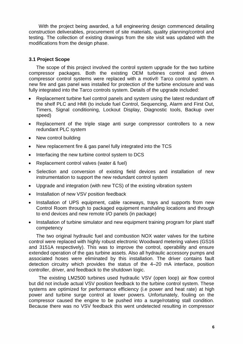
With the project being awarded, a full engineering design commenced detailing construction deliverables, procurement of site materials, quality planning/control and testing. The collection of existing drawings from the site visit was updated with the modifications from the design phase.
3.1 Project Scope
The scope of this project involved the control system upgrade for the two turbine compressor packages. Both the existing OEM turbines control and driven compressor control systems were replaced with a motiv® Tarco control system. A new fire and gas panel was installed for protection of the turbine enclosure and was fully integrated into the Tarco controls system. Details of the upgrade included:
Replacement turbine fuel control panels and system using the latest redundant off the shelf PLC and HMI (to include fuel Control, Sequencing, Alarm and First Out, Timers, Signal conditioning, Lockout Display, Diagnostic tools, Backup over speed)
Replacement of the triple stage anti surge compressor controllers to a new redundant PLC system
New control building
New replacement fire & gas panel fully integrated into the TCS
Interfacing the new turbine control system to DCS
Replacement control valves (water & fuel)
Selection and conversion of existing field devices and installation of new instrumentation to support the new redundant control system
Upgrade and integration (with new TCS) of the existing vibration system
Installation of new VSV position feedback
Installation of UPS equipment, cable raceways, trays and supports from new Control Room through to packaged equipment marshaling locations and through to end devices and new remote I/O panels (in package)
Installation of turbine simulator and new equipment training program for plant staff competency
The two original hydraulic fuel and combustion NOX water valves for the turbine control were replaced with highly robust electronic Woodward metering valves (GS16 and 3151A respectively). This was to improve the control, operability and ensure extended operation of the gas turbine assets. Also all hydraulic accessory pumps and associated hoses were eliminated by this installation. The driver contains fault detection circuitry which provides the status of the 4–20 mA interface, position controller, driver, and feedback to the shutdown logic.
The existing LM2500 turbines used hydraulic VSV (open loop) air flow control but did not include actual VSV position feedback to the turbine control system. These systems are optimized for performance efficiency (i.e power and heat rate) at high power and turbine surge control at lower powers. Unfortunately, fouling on the compressor caused the engine to be pushed into a surge/rotating stall condition. Because there was no VSV feedback this went undetected resulting in compressor
7
damage. The engine had to be removed and sent off site for repair. A LVDT was installed to provide position feedback for the VSV‟s and the HMI had a screen added to watch and alarm against the VSV schedule.
The existing Bently Nevada 3500 vibration monitoring systems (for the turbine and driven compressor units) was relocated to the new TCS cabinets located in the new turbine control building. Vibration monitoring signals were integrated into the motiv TCS system, Foxboro DCS system & the newly developed turbine HMI system.
The TCS was integrated into the DCS because there is instrumentation in the TCS system that is not available to the DCS. It also allows the remote alarm systems (pagers, cell phones etc) to flow through to the operators.
The plant systems were to be designed in a redundant fashion so that any loss of one component would not cause the turbine package to shut down. The Allen-Bradley PLC controller had two systems installed (one live and one backup with a dual communications card), dual power supplies were added and any instrumentation associated with package / balance of plant control was doubled up.
Figure 4: Basic Control System Structure
8
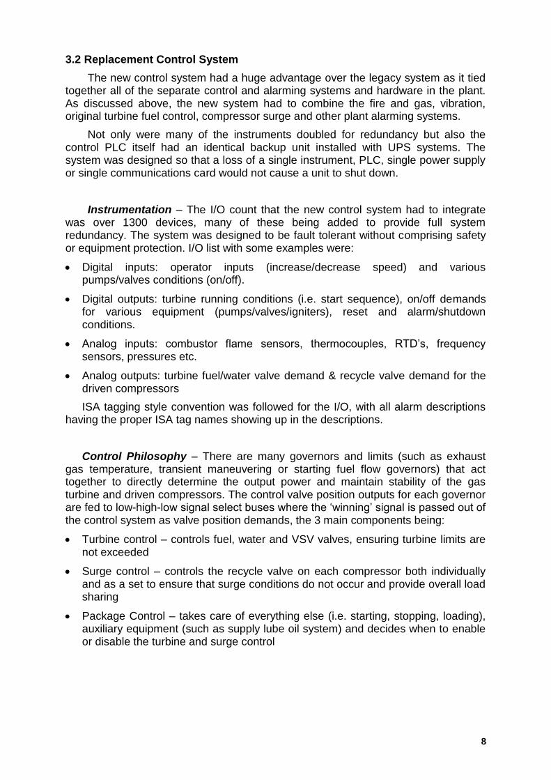
3.2 Replacement Control System
The new control system had a huge advantage over the legacy system as it tied together all of the separate control and alarming systems and hardware in the plant. As discussed above, the new system had to combine the fire and gas, vibration, original turbine fuel control, compressor surge and other plant alarming systems.
Not only were many of the instruments doubled for redundancy but also the control PLC itself had an identical backup unit installed with UPS systems. The system was designed so that a loss of a single instrument, PLC, single power supply or single communications card would not cause a unit to shut down.
Instrumentation – The I/O count that the new control system had to integrate was over 1300 devices, many of these being added to provide full system redundancy. The system was designed to be fault tolerant without comprising safety or equipment protection. I/O list with some examples were:
Digital inputs: operator inputs (increase/decrease speed) and various pumps/valves conditions (on/off).
Digital outputs: turbine running conditions (i.e. start sequence), on/off demands for various equipment (pumps/valves/igniters), reset and alarm/shutdown conditions.
Analog inputs: combustor flame sensors, thermocouples, RTD‟s, frequency sensors, pressures etc.
Analog outputs: turbine fuel/water valve demand & recycle valve demand for the driven compressors
ISA tagging style convention was followed for the I/O, with all alarm descriptions having the proper ISA tag names showing up in the descriptions.
Control Philosophy – There are many governors and limits (such as exhaust gas temperature, transient maneuvering or starting fuel flow governors) that act together to directly determine the output power and maintain stability of the gas turbine and driven compressors. The control valve position outputs for each governor are fed to low-high-low signal select buses where the „winning‟ signal is passed out of the control system as valve position demands, the 3 main components being:
Turbine control – controls fuel, water and VSV valves, ensuring turbine limits are not exceeded
Surge control – controls the recycle valve on each compressor both individually and as a set to ensure that surge conditions do not occur and provide overall load sharing
Package Control – takes care of everything else (i.e. starting, stopping, loading), auxiliary equipment (such as supply lube oil system) and decides when to enable or disable the turbine and surge control
9
Human-Machine-Interface (HMI) – Two PanelView Plus 1500 HMI‟s were installed to replace the existing system. The goal was to keep as much of the layout similar (for staff familiarity), but improve key screens so that operators did not have to flip back and forth, in order to perform one function. For example performing the startup of a turbine unit had all the required parameters for that procedure.
Allen Bradley Factory Talk View software platform was used and various performance displays (efficiencies, heat rate and power output) were included. Navigation through the HMI screens was improved with a two line selection bar (top row buttons for main headings and bottom row buttons for sub-categories).
Figure 4: Two line HMI Navigation Bar
During the project, the compressor units were tested and mapped out to verify the surge margin characteristics. New compressor load sharing control was added which compared all the units and determined the one with lowest percentage from surge. The highest unit of the set would be trimmed back on speed to balance the whole train and allowing more gas flow through other units. This vastly improved overall operation but also added stability to the equipment that improved other running conditions such as starting.
10
3.3 Turbine Simulator
For training and troubleshooting purposes, a unique solution was implemented at the plant to provide competency for existing and future plant operators/technicians. The improvement of plant operator understanding of the key facility assets was one of the main drivers for the project. A simulator system was installed in the PLC system that could be used to demonstrate:
Normal plant control system operation
Control system response in abnormal conditions (e.g. what happens when a particular transmitter fails)
System configuration testing (e.g. transmitter scaling, set point modification) of both the software and electrical systems
Control system hardware troubleshooting
The software simulator drives every I/O point in the system. There are settings for automatic, hardware and manual modes:
When in automatic, the I/O point responds in a typical running fashion.
Hardware: the point is re-mapped to the simulator hardware, allowing testing and simulation using actual transmitters. For example, a technician can connect a transmitter to one of the analog input channels and calibrate the 4-20 device and configure its scaling and alarm set points from the display.
Manual: when in manual, the operator can set the value (on/off or analog) to any value. This allows realistic training scenarios (limit switch‟s which don‟t trip, analog values that decay). It also allows exact duplication of actual events, allowing cross training of operator shifts from incidents that may occur in the plant. For example, if the ignitors are enabled, the fuel valve is open and there is fuel supply pressure then the simulator will increase the T5 temperatures to simulate ignition.
The set points (e.g. pressurizing timers) can also be changed to modify how the simulator works. The simulator alarm logger will display any errors in the system, such as input faults.
The hardware portion of the simulator is used as a “hot” spare depot in addition as replicating each hardware circuit. This gives confidence that spare parts are at the correct firmware, revision level etc. It also allows realistic training, as the prints and circuits are the same as the main project. This allows tech‟s to become familiar with the system without working on live equipment.
Both hardware and software allow testing of maintenance or training procedures on the simulator before implementing them on the live system, saving time by not having to start the unit from a de-pressurized state. This has already prevented several shutdowns as operators and E&I technicians were able to practice a replacement of a defective part, involving jumpers and software with the simulator demonstrating a shutting down. Without the simulator this would have resulted in a plant shut down, with an obvious downtime and cost saving.
11
3.3 Construction and Commissioning
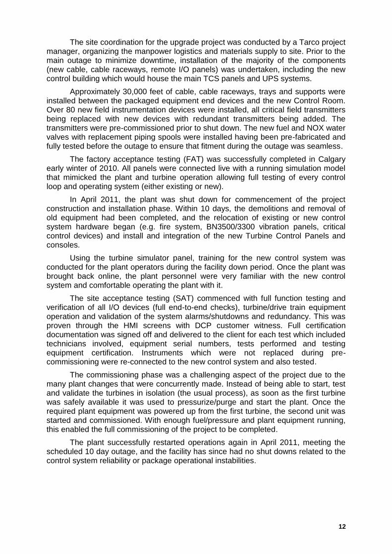
This plant turnaround was the largest in its history, with hundreds of other contractors cleaning, replacing and adding new vessels, piping and other equipment. In addition to normal turn around activities, the exhaust collectors, stacks and one of the engines was replaced. This additional work in and around the area of the new control system demanded very detailed and flexible planning.
Installing the new electronic fuel valve
New field transmitters for the driven
compressors
Newly installed cable raceways
New VSV feedback LVDT installed
Figure 5: Install of various on-site hardware
12
The site coordination for the upgrade project was conducted by a Tarco project manager, organizing the manpower logistics and materials supply to site. Prior to the main outage to minimize downtime, installation of the majority of the components (new cable, cable raceways, remote I/O panels) was undertaken, including the new control building which would house the main TCS panels and UPS systems.
Approximately 30,000 feet of cable, cable raceways, trays and supports were installed between the packaged equipment end devices and the new Control Room. Over 80 new field instrumentation devices were installed, all critical field transmitters being replaced with new devices with redundant transmitters being added. The transmitters were pre-commissioned prior to shut down. The new fuel and NOX water valves with replacement piping spools were installed having been pre-fabricated and fully tested before the outage to ensure that fitment during the outage was seamless.
The factory acceptance testing (FAT) was successfully completed in Calgary early winter of 2010. All panels were connected live with a running simulation model that mimicked the plant and turbine operation allowing full testing of every control loop and operating system (either existing or new).
In April 2011, the plant was shut down for commencement of the project construction and installation phase. Within 10 days, the demolitions and removal of old equipment had been completed, and the relocation of existing or new control system hardware began (e.g. fire system, BN3500/3300 vibration panels, critical control devices) and install and integration of the new Turbine Control Panels and consoles.
Using the turbine simulator panel, training for the new control system was conducted for the plant operators during the facility down period. Once the plant was brought back online, the plant personnel were very familiar with the new control system and comfortable operating the plant with it.
The site acceptance testing (SAT) commenced with full function testing and verification of all I/O devices (full end-to-end checks), turbine/drive train equipment operation and validation of the system alarms/shutdowns and redundancy. This was proven through the HMI screens with DCP customer witness. Full certification documentation was signed off and delivered to the client for each test which included technicians involved, equipment serial numbers, tests performed and testing equipment certification. Instruments which were not replaced during pre-commissioning were re-connected to the new control system and also tested.
The commissioning phase was a challenging aspect of the project due to the many plant changes that were concurrently made. Instead of being able to start, test and validate the turbines in isolation (the usual process), as soon as the first turbine was safely available it was used to pressurize/purge and start the plant. Once the required plant equipment was powered up from the first turbine, the second unit was started and commissioned. With enough fuel/pressure and plant equipment running, this enabled the full commissioning of the project to be completed.
The plant successfully restarted operations again in April 2011, meeting the scheduled 10 day outage, and the facility has since had no shut downs related to the control system reliability or package operational instabilities.
13
4 Conclusions
The upgraded facility control system has shown a marked improvement in the reliability and availability of the Goldstream plant. The project was completed within the 10 day schedule, ensuring that the plant downtime was kept to a minimum. The main benefits of this project are summarized as follows:
Improved Reliability and Operability – With added operation controllers on the compressors, they are able to handle far more plant upsets without having the engine shutdown. These controllers also allow additional recycling, keeping sub parts of the plant operating far longer in upset conditions.
Surge control integrated into the control system has allowed clearer and better tuning without adding risk to the compressors. This has allowed for one button start and loading of the turbines, greatly increasing reliability and speed of coming to full power after a shutdown. This benefit is compounded, as starting operations are only done when operator‟s attention is needed in other parts of the plant as well.
Reliability benefits equate back to better throughput, less flaring and overall improved customer satisfaction. Runtime on these two units has been close 100% since the control system was installed and commissioned. This is in comparison to 96% to 98% runtime before the upgrade (160mmcfd X 98% = 156.8mmcfd, LPO = 3.2mmcfd or 11680mmcf/yr). The NOX emissions reduction has kept the plant within the state mandated limits, and reduction in flaring due to the plant being tripped off-line has seen the same reduction as the increase in runtime percentage. The new system is far more cost effective, as the common use of PLC I/O cards rather than separate systems.
Better Troubleshooting – The operators‟ visibility of the plant equipment has been improved. For example, by installing differential pressure switch transmitters between each compressor the operators can determine any issues on a component level. With the original system if a valve sequence failed the challenge was identifying it out of several valves or pressure points failing. New system alarms point to the exact device (valve, switch etc.)
Common platform – The new system brings everything into a common platform with better HMI‟s. Previously the client could not see load sharing or compressor information. New process controls added, with all of the information/alarms on one screen due to better access to the system (process overrides on recycle valves.)
Training and other – Plant personnel are trained on-site via the turbine simulator, providing a competency tool for staff, with improved troubleshooting knowledge and a safe method for testing hardware change without the risk of tripping the facility. The open architecture philosophy of the control system will provide further improvements, such as the planned future turbo-expander and BMS projects at the site.