Modifications in the Driving System of a Conventional Car for
Paraplegic People
Surve Sumit1, Bavdhankar Vaibhav2, Chavan Amit3, Desai Subodh4, Shitut Chinmay5
1Asst. Professor, Dept. of Automobile Engineering, Rajendra Mane College of Engineering & Technology, Ambav, Maharashtra, India
2Student, Dept. of Automobile Engineering, Rajendra Mane College of Engineering & Technology, Ambav, Maharashtra, India
3Student, Dept. of Automobile Engineering, Rajendra Mane College of Engineering & Technology, Ambav, Maharashtra, India
4Student, Dept. of Automobile Engineering, Rajendra Mane College of Engineering & Technology, Ambav, Maharashtra, India
5Student, Dept. of Automobile Engineering, Rajendra Mane College of Engineering & Technology, Ambav, Maharashtra, India
---------------------------------------------------------------------***---------------------------------------------------------------------Abstract - Human beings have an inseparable relationship with vehicles. From being nothing more than a commutative commodity, it has become a feature of comfort, luxury & long distance travel journeys. However, that cannot be said for the people who are physically disabled & are unable to drive vehicles due to their paraplegic disability. The objective of this project is to modify the driving system of a conventional manual transmission vehicle so that even paraplegic people can drive the vehicle without any difficulty. In this project, the major components that we have focused on are the foot pedals i.e. Accelerator, Brake & Clutch pedals. The Accelerator pedal will be controlled as in like a traditional motorbike i.e. via a handle. The brake pedal will be controlled via a mechanical push-rod & the clutch pedal will be controlled via an electronic servo motor. All of this will completely eliminate the need of legs for driving thereby providing paraplegic people to drive the vehicle.
This project was inspired by the people those who have passion for driving but are unable to do so because they have lost the usage of their legs. There are many people who are unable to drive vehicles due to the physical disability that they face, may that be paraplegic or any other.
Paraplegia is defined as ‘impairment in motor or sensory function of the lower extremities’. It is usually caused by spinal cord injury or a congenital condition that affects the neural elements of the spinal canal. Common victims of this impairment include members of the armed forces, people who have met with an automobile accident or due to falls from heights.
Even the paraplegics need to have mobility. However, they are completely dependent on other people to travel or commute. This project aims to enable paraplegics & double leg amputees to safely drive & operate a manual transmission automobile. The existing systems that are in use are mostly targeted towards automatic transmission cars & devices that are present for manual transmission vehicles limit the driving experience for the user due to the need to use both the hands for operating accelerator & brake, & thereby limiting the ability to operate the clutch. Also, these devices are expensive & cost more than ₹30,000. Living with a disability is itself expensive & hence one of the team’s objectives is to keep the costs of the components to a minimum so that there will be no additional burden on the disabled people.
2. LITERATURE REVIEW
For any project, it is necessary to conduct an extensive background research & review the literature content available.
2.1 Disabilities in India
As per Census 2011, in India, out of the 121 Crore population, about 2.68 Crore people are ‘disabled’ which is the 2.21% of the total population. 20% of the disabled persons are having disability in movement, 19% are with disability in seeing & other 19% are with disability in hearing. 8% of the population has multiple disabilities. Also, the number of total disabled people is the highest in the age group of 10-19 years at 17% (46.2 lakhs) followed by the age group 20-29 which is about 16% [1].
All of this statistical data is provided through various surveys conducted by the Govt. of India. This data provides a complete structured data to assess the state of disabled people in our country. Hence, when it comes to providing mobility solutions, it becomes necessary to consider the cost of driver assistance device that should be provided.
International Research Journal of Engineering and Technology (IRJET) e-ISSN: 2395 -0056
Today in the market there are countless numbers of devices that provide driving assistance in an automobile. This section includes some of the devices that are currently available worldwide as well as a couple of devices specifically in India.
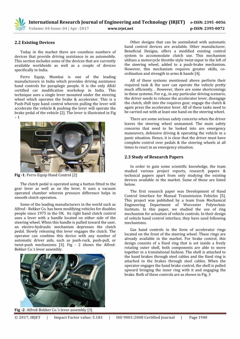
Ferro Equip, Mumbai is one of the leading manufacturers in India which provides driving assistance hand controls for paraplegic people. It is the only ARAI certified car modification workshop in India. This technique uses a single lever mounted under the steering wheel which operates the brake & accelerator. This is a Push-Pull type hand control wherein pulling the lever will accelerate the vehicle & pushing the lever will operate the brake pedal of the vehicle [2]. The lever is illustrated in Fig – 1
Fig -1: Ferro Equip Hand Control [2]
The clutch pedal is operated using a button fitted to the
gear lever as well as on the lever. It uses a vacuum operated chamber wherein pressure difference helps in smooth clutch operation.
Some of the leading manufacturers in the world such as Alfred - Bekker Co. has been modifying vehicles for disables people since 1975 in the UK. Its right hand clutch control uses a lever with a handle located on either side of the steering wheel. When this handle is pulled toward the user, an electro-hydraulic mechanism depresses the clutch pedal. Slowly releasing this lever engages the clutch. The operator can combine this device with any number of automatic driver aids, such as push-rock, push-pull, or twist-push mechanisms [3]. Fig - 2 shows the Alfred-Bekker Co.’s lever assembly.
Fig -2: Alfred-Bekker Co.’s lever assembly [3]
Other designs that can be assimilated with automatic hand control devices are available. Other manufacturer, Beneficial Designs, offers a modified existing control system to accommodate clutch use. This mechanism utilizes a motorcycle throttle-style twist-input to the left of the steering wheel, added to a push-brake mechanism. However, this mechanism requires greater skills, co-ordination and strength in arms & hands [4].
All of these systems mentioned above perform their required task & the user can operate the vehicle pretty much efficiently. . However, there are some shortcomings in these systems. For e.g., in any particular driving scenario, the driver needs to release the accelerator lever, disengage the clutch, shift into the requires gear, engage the clutch & again press the accelerator lever. All of these tasks need to be carried out with at least one hand on the steering wheel.
There are some serious safety concerns when the driver leaves the steering wheel unmanned. The main safety concerns that need to be looked into are emergency maneuvers, defensive driving & operating the vehicle in a panic situation. Hence, it is clear that the driver must have complete control over pedals & the steering wheels at all times to react in an emergency situation.
2.3 Study of Research Papers
In order to gain some scientific knowledge, the team studied various project reports, research papers & technical papers apart from only studying the existing devices available in the market. Some of those are listed below.
The first research paper was Development of Hand Control Interface for Manual Transmission Vehicles [5]. This project was published by a team from Mechanical Engineering Department of Worcester Polytechnic Institute. In this paper, we studied the use of ring mechanism for actuation of vehicle controls. In their design of vehicle hand control interface, they have used following mechanisms.
Gas hand controls in the form of accelerator rings located on the front of the steering wheel. These rings are already available in the market. For brake control, this design consists of a fixed ring that is set inside a freely rotating outer shell, both components are able to move together in a translational fashion. The shell is attached to the hand brakes through steel cables and the fixed ring is attached to the brakes through steel cables. When the operator engages the hand brake control, the shell is pulled upward bringing the inner ring with it and engaging the brake. Both of these controls are as shown in Fig. 3
International Research Journal of Engineering and Technology (IRJET) e-ISSN: 2395 -0056
The placement of the new clutch control in this design was placed on shifting knob, because the actuating of the clutch and shifting gears are an independent system used concurrently. Bowden cable (bicycle cable) is used for the actuation of clutch. Starting from the clutch pedal, the cable is attached at the lowest point of the pedal and travels straight back and along the wall. The cable travels along the console, up and to the shifting lever [5]. The complete prototype of their design is as shown in Fig – 4
Fig -4: Prototype of Hand Controls [5]
There are few areas in this project which should be improved. Enclosures of each moving part is important for the safety purpose. Also, due to the side rails incorporated in the steering, the mechanism installation becomes difficult. So, the further modifications are necessary.
The next paper was Development of Zero-Leg Input Manual Transmission Interface. It was published by a team from Mechanical Engineering Department of Worcester Polytechnic Institute. In this project, concentric brake and throttle ring is used and clutch is operated with the help of knob on gear lever. The throttle ring is placed on driver-facing side and brake ring on dash side of the steering wheel. Fig - 5 shows a schematic for such a mechanism.
Fig -5: Schematic for Controls near Driver Seat [6]
The rings are mounted on the steering column with the help of side rails. The ring present in front facing when pushed, it actuates the throttle. Also, the ring present on the dash side when pulled towards the steering actuates the brake mechanism [6].
The third paper was Design & Development of Driving System for Disabled Driver. It paper was published by Department of Mechanical Engineering, Kulliyyah of Engineering, International Islamic University Malaysia at World Engineering Congress 2010, Malaysia.
In this paper, the complete steering control of the vehicle is changed. With the certain degrees of rotation then it will transfer the movement to the potentiometer as input to the microcontroller. The motor will amplify the rotation to the lower steering shaft to transfer the movement to the rack and pinion directly to the tires [7]. Fig - 6 shows the arrangement of the components of the system.
Fig -6: New System Developed for Hand Controls [7]
For brakes and accelerator mechanisms similar to the one used in motorcycles It is just like riding a motorcycle. The conventional system of braking and acceleration by foot pedals have been changed to hand operated mechanism as in motorcycle so that disabled people without lower limb can comfortably drive .
The last paper was about Fabrication of Hand Operated Clutch in Four Wheelers. This paper was published by Automobile Engineering Department from Christ The King Engineering College, Coimbatore, India [8].
Use of button or a switch at the top of gear lever is done for the operation of clutch. The working of clutch is made electromagnetic by using various components like motor, belt & pulley, control unit and electromagnetic hand clutch. The arrangement as shown in fig - 7 consists of button or switch, gear lever, DC motor, electromagnetic clutch, wheel, frame stand.
International Research Journal of Engineering and Technology (IRJET) e-ISSN: 2395 -0056
Fig -7: Arrangement of Hand Clutch [8] This hand operated clutch is economical, electromagnetic care performance is good and physical and mechanical properties of material are safe. The vehicle can run in a smooth operation and can be avoided with sudden accidents and can be used in traffics.
3. BASIC THEORY
In this section, we shall take a look the mechanics of driving a manual transmission automobile and also have a glimpse at some of the different actuation systems used in mechanics.
3.1 Basic Mechanics of Driving an Automobile
Automobiles can be broadly classified into 2 categories as Manual Transmission Vehicles & Automatic Transmission Vehicles. Driving, especially a manual transmission car requires higher skill than an automatic transmission car. The driver has to control various inputs at the same time using only his hands & feet & at the same time remain alert & keep an eye on the road.
The driver has to control at least 6 inputs using his 2 hands & 2 feet. When considering that the vehicle needs to be completely driven by hands it is necessary that all the 6 inputs shall be controlled only by hands. The driver must be able to operate all of the systems without inducing any fatigue & difficulty which can hinder his driving experience.
3.2 Actuation Systems
When considering the design systems for operation of the pedals by hand, various systems were considered. These systems are broadly classified upon the medium they utilize for actuating the pedals [6].
In electronic systems, all of the controls are controlled electronically by a microcontroller usually coupled with a motor. This motor can either be a servo motor or simple motor. The advantage of servo motor is that it provides continuous feedback to the system & adjusts its inputs accordingly. But it requires higher cost.
Hydraulic systems consist of a piston-cylinder & a reservoir in which a liquid (usually oil) is filled. . Hydraulic
systems do not require electric power to work. Hence, they can work even when the vehicle is off. However, these systems require more space as there is necessity to store the fluid in tanks.
Mechanical systems are the oldest type of systems used for actuating machines. Mechanical systems rely on linkages, gears, levers, cams, etc. Once these systems are designed, it is not possible to easily change or modify them. Also, they require large space as compared to other systems.
Pneumatic systems function similarly to hydraulic systems, but rather than using a liquid, it relies on compressed air. The air pressure would have to be monitored constantly, which means more devices in place, meaning more cost. Also, similar to a hydraulic system, they would need large area for the tanks that hold the air.
3.2 Hand Grips
The entire driving assistance hand controls are purely based on the hand capabilities of disabled people. The grip of the hand on the levers should be strong under acceleration as well as braking.
Hand grip strength reflects the maximum strength derived from combined contraction of extrinsic and intrinsic hand muscles which lead to the flexion of hand joints. The power grip is the result of forceful flexion of all finger joints with the maximum voluntary force that a subject is able to exert under normal bio-kinematic conditions [5].
Hence, studying some of the most common hand grips utilized by people in operations related to using mechanical objects is essential to find the optimum hand grip that should be utilized to operate the driving controls.
In Power Grip, the hand grabs the object using all of the fingers. As a result, maximum amount of surface area of object is grasped. Hence, this grip is used in applications where greater amount of forces is required as it provides the highest force amongst different grips. The reason that we use power grip for operating our mechanism is that the dominant hand applies higher force of about 62 kg. Hence this force is sufficient for the actuation of the mechanism & used. Fig - 8 illustrates Power Grip.
Fig -8: Power Grip
International Research Journal of Engineering and Technology (IRJET) e-ISSN: 2395 -0056
When it comes to projects, it is necessary that certain objectives should be defined so that we can focus on achieving that pre-defined goal in a structured approach.
4.1 Aim
The aim of this project is to design & install special accessories in a conventional car without degrading the vehicle performance & hindering normal driving of the vehicle.
4.2 Objectives
While working towards this aim, it was necessary that certain objective need to be defined so that the reachability of the aim becomes easier & straightforward. The objectives that we had defined are as follows:
1. To design various accessories for the brake, clutch & accelerator system
2. To modify a conventional car with special accessories
5. DESIGN & DEVELOPMENT OF DRIVING DEVICE
Now we will about the design process that we have
adopted. Along with that, the specifications of the device that we had decided for the project.
5.1 Design Process
Engineering design is the process of devising a system, component or process to meet the desired needs. It is a decision-making process in which the basic sciences, mathematics & engineering sciences are applied to optimally convert resources to meet a stated objective. The engineering design process is a series of steps that engineers follow when they are trying to solve a problem & design a solution for something.
5.2 Specifications
Specifications provide a brief overview about what the product. It describes the features of the solutions referring to the design.
1. Driver must be able to drive the vehicle safely and comfortably.
2. Driver must be able to operate all the pedals independently.
3. All the pedals must be easy to reach.
4. Driver must be able to always have at least one hand on steering wheel.
5. Driver must be able to start and stop the vehicle on gradient.
6. Response time between input & operation must be less.
7. The device should be reliable & safe.
8. The device should not hinder normal driving experience.
9. Device should occupy minimum space.
10. There should be minimum free play.
11. It should be able to remove and assembled in minimum period of time.
12. The device should cost as low as possible & require less maintenance.
5.3 Idea Generation & Finalization of Idea
When the project was finalized, it was necessary to create some solutions that would be significantly different than the ones available in the market. Hence, the team utilized brainstorming sessions wherein various ideas related to design were put forward.
Also, the team had to make sure that the controls that were to be designed should be able to provide a complete driving experience to the driver. However, this requires providing ample space to the device. Another problem that the team had to ponder upon was the fact that even though manual transmission vehicles have 3 pedals, their shapes & sizes differ significantly from each other. Also, the forces required to press the pedals, their travel path as well as full depression distances are different. Hence, the team had to make sure that the design should be as universal as possible.
The team also had constraints for cost. The designed device should provide equal performance as the existing systems or better than those & at the same time be cheaper or at the most equal in cost with them.
So, after careful thought process, the team narrowed down to 4 ideas for the operation of brake & accelerator as well as 2 different solutions as to how the clutch can operate.
First idea was about using Push-Pull mechanism for accelerator & brake. The entire assembly will be mounted under the steering wheel. It is based upon current industry standard mechanism in which push will operate brake pedal & pulling the lever will operate accelerator pedal. CAD model designed for such model is shown in fig – 9.
Fig -9: CAD Model of Push - Pull Mechanism
International Research Journal of Engineering and Technology (IRJET) e-ISSN: 2395 -0056
This hand control consists of 5 components. Left most portion is design of grip. Black section immediately after it is connecting arm. Right-most rod will be connected to accelerator pedal and another to brake pedal. L-shaped lever acts as a support to entire system attached to underside of dashboard. The clutch would be controlled electronically & hence would have further increased the costs.
However, such a design was very common with almost all the solutions available in the market & hence, they had similar drawbacks inherent in them.
Other mechanism that we have tried to use is Pull-Rock mechanism incorporating all the three pedals. This mechanism was loosely based upon the Push-Rock Hand Control design. But, instead of pushing the lever, it will be the pulling action that will operate the accelerator. Also, an innovative idea was put forward by the team members that during the rocking mechanism, the clutch as well as the brake pedal will operate. There were to be 2 controls for the ‘rocking’ operation. In this, a certain distance of rocking the lever will depress the clutch completely for shifting of gears & when the rock lever will travel its complete distance, the brake pedal will operate.
However, this design had dome drawbacks in that the basic objective was not met. The major problem was that while shifting, the driver’s hands had to be on the clutch lever as well as on the gear shifter leaving the steering wheel unattended. This possessed serious safety concerns. Another problem was that during clutch engagement, we need gradual engagement so that vehicle moves smoothly. This was not possible completely. Also, as there were two controls in one motion only, it could have become a bit confusing for the driver during emergency & panic situation.
The next idea was about usage of Paddle Shifters. This design was similar to the paddle gear shifters used in the Formula 1 Racing Cars. There were to be 2 different levers which will operate the brake & accelerator. These 2 paddles will be below the steering wheel in two directions & will be called as Right Paddle & Left Paddle. An illustrative sketch of Paddle Shifters is shown in Fig – 10.
Fig -10: Paddle Shifters in Conventional Cars
The right paddle will operate the brake & the left paddle will operate the accelerator when the respective paddles are pulled by the driver. For this control, there would have been a button mounted on the accelerator paddle which operates the clutch.
This design, however, utilized more space than other design considerations. Also, the button incorporated in the accelerator paddle would have to be electronically controlled by a microcontroller/microprocessor. This would have increased the cost of the device significantly.
Then team had thought about use of Twist–Push mechanism. Twist-Push design utilizes a twisting action for accelerator control & pushing action to operate the brake. Twisting the end of the handle counter-clockwise would accelerate the vehicle & leaving it as it is would again decelerate the vehicle. Also, pushing to operate the brake would be easily done as there is only one action that the levers need to perform. CAD Model designed using Autodesk Inventor 2016 for this mechanism is shown in fig – 11
Fig – 11: Twist Push Mechanism
After finalizing this idea for the accelerator & brake pedals, we concentrated our efforts on inventing up a solution to operate the clutch pedal. The first idea that we developed was controlling the clutch electronically via a microcontroller. However, this would have increased the cost. Hence unanimously the team decided to discard this idea.
Another idea was to develop a mechanical linkage for the clutch. The mechanical linkages would require some more force that the driver needs to operate the clutch but these systems would cost significantly less. . There will be a lever present that, on pushing, will press the clutch pedal. The driver will lock lever in to the slot using his left hand & shift the gear & shall again unlock the lever. There will also be a similar locking mechanism on the accelerator which can be used for setting the accelerator at a certain engine speed. This setting could be used during starting the vehicle motion from a gradient.
The advantage at least one hand of the driver shall always remain on the steering wheel. However, the driver would need to practice using these controls thoroughly. This system will cost significantly less than the existing systems. As there are less complicated & no electronic parts, the maintenance of this device will be less.
5.4 Measurements
It was necessary to take certain measurements so that the CAD Model could be designed. Also, there were photographs taken of the interior of the vehicle. The photographs were useful in determining the overall layout of the driving seat as well as for calculation of dimensions.
International Research Journal of Engineering and Technology (IRJET) e-ISSN: 2395 -0056
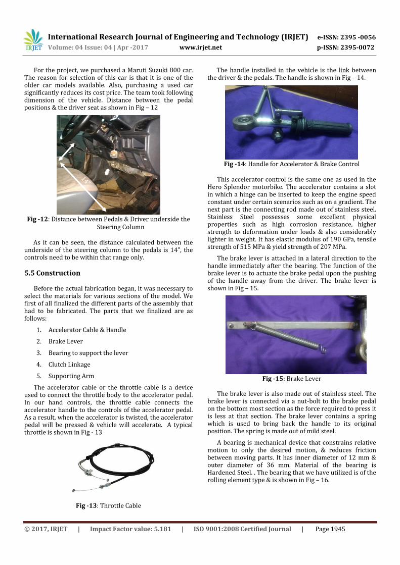
For the project, we purchased a Maruti Suzuki 800 car. The reason for selection of this car is that it is one of the older car models available. Also, purchasing a used car significantly reduces its cost price. The team took following dimension of the vehicle. Distance between the pedal positions & the driver seat as shown in Fig – 12
Fig -12: Distance between Pedals & Driver underside the
Steering Column
As it can be seen, the distance calculated between the underside of the steering column to the pedals is 14”, the controls need to be within that range only.
5.5 Construction Before the actual fabrication began, it was necessary to
select the materials for various sections of the model. We first of all finalized the different parts of the assembly that had to be fabricated. The parts that we finalized are as follows:
1. Accelerator Cable & Handle
2. Brake Lever
3. Bearing to support the lever
4. Clutch Linkage
5. Supporting Arm
The accelerator cable or the throttle cable is a device used to connect the throttle body to the accelerator pedal. In our hand controls, the throttle cable connects the accelerator handle to the controls of the accelerator pedal. As a result, when the accelerator is twisted, the accelerator pedal will be pressed & vehicle will accelerate. A typical throttle is shown in Fig - 13
Fig -13: Throttle Cable
The handle installed in the vehicle is the link between the driver & the pedals. The handle is shown in Fig – 14.
Fig -14: Handle for Accelerator & Brake Control
This accelerator control is the same one as used in the
Hero Splendor motorbike. The accelerator contains a slot in which a hinge can be inserted to keep the engine speed constant under certain scenarios such as on a gradient. The next part is the connecting rod made out of stainless steel. Stainless Steel possesses some excellent physical properties such as high corrosion resistance, higher strength to deformation under loads & also considerably lighter in weight. It has elastic modulus of 190 GPa, tensile strength of 515 MPa & yield strength of 207 MPa.
The brake lever is attached in a lateral direction to the handle immediately after the bearing. The function of the brake lever is to actuate the brake pedal upon the pushing of the handle away from the driver. The brake lever is shown in Fig – 15.
Fig -15: Brake Lever
The brake lever is also made out of stainless steel. The
brake lever is connected via a nut-bolt to the brake pedal on the bottom most section as the force required to press it is less at that section. The brake lever contains a spring which is used to bring back the handle to its original position. The spring is made out of mild steel.
A bearing is mechanical device that constrains relative motion to only the desired motion, & reduces friction between moving parts. It has inner diameter of 12 mm & outer diameter of 36 mm. Material of the bearing is Hardened Steel. . The bearing that we have utilized is of the rolling element type & is shown in Fig – 16.
International Research Journal of Engineering and Technology (IRJET) e-ISSN: 2395 -0056
supported is made out of mild steel. The reason for using roller bearing is that they offer higher working loads & cause little friction for smooth operation. However, the cost of these bearings is a bit expensive which can be a trade-off for increased performance consideration.
The clutch pedal was to be operated by using mechanical linkage. Hence, it was necessary that the material should withstand the forces developed during operation but also provide reliability & ease of operation.
The linkage consists of 2 components viz. the hinge & the rod. The rod is made out of a variant of mild steel & the hinge is made out of stainless steel. The rod is attached to the clutch pedal while the hinge is operated by the driver during driving. The hinge is inserted in a slot of via a hole. The following Fig - 17 shows the clutch linkage attached in the vehicle.
Fig -17: Clutch Linkage
The procedure to shift gears using this mechanism is as
follows:
1. Push the hinge into the slot
2. Shift into required gear
3. Unhook the hinge from the slot
As it uses mechanical linkages, the power required to operate the clutch is high. However, with extensive practice one can easily operate the vehicle in almost any condition.
5.6 Fabrication
All of the above parts were fabricated by the team with the help of Piyush TIG Works, Kolhapur. All the joints are done by electric arc welding process. The purpose of using
this process to join the metals is due to its low cost all the while providing sufficient strength to resist generated forces [10].
The accelerator control is a part of handle of Hero Splendor motorbike. The required part was cut & arc welded to the bearing insert. A stopper is welded near the throttle control to lock the engine speed at certain rpm. The throttle cable is connected to a strip welded to the accelerator pedal.
The brake lever is also connected to the main handle. A rod end is used to connect the lever. The thread section of the rod end is removed & the head section is arc welded to the main handle. At one end of the brake linkage, the threaded section of a M12 sized bolt is welded. At the other end, one hole of 6 mm diameter is drilled through the lever is connected to the pedal.
The main component is of the clutch linkage is the 10mm square bar, both ends of which are drilled with a 6mm hole. On the clutch pedal, a M6 bolt is arc welded in which one end of the linkage is connected. The other end is connected to a lever using nut bolt of size M6. The lever contains a circular slot of diameter 12 mm which is used to keep the clutch disengaged. The clutch lever is inserted in a rod, which is arc welded to a L shaped strip which supports the entire assembly.
A 10mm rod is also welded to the L shaped metal strip which is used to temporarily hold the lever pressed. A small metal strip is welded between the accelerator handle & the clutch assembly to provide sufficient strength to the complete driving assembly.
6. TESTING OF COMPLETE ASSEMBLY
After the complete design was fabricated, it was necessary that the controls be tested extensively & in various conditions. The completely assembled device when attached to the vehicle is shown in Fig – 18.
Fig -18: Complete Assembled Hand Controls to Vehicle
The team decided to perform the first test on the vehicle
in the institute premises. The institute road was primarily used for this purpose. The map of the institute road where the test was performed is shown in Fig – 19.
International Research Journal of Engineering and Technology (IRJET) e-ISSN: 2395 -0056
The purpose of using this particular road as a test track
is the fact that it contains gradients, sharp turns as well as straight roads. Hence, nearly all types of road conditions can be simulated without the need for going elsewhere. In this particular test track, the black color indicates the going direction while the blue color indicates the return direction.
The team performed following simulations successfully on the vehicle:
1. Starting the vehicle from rest on level road surface
2. Making sharp turns while driving at 15 km/hr.
3. Braking the vehicle on downward slope & starting again
4. Tackling a turn at a higher speed
5. Sudden stoppage & restart
6. Stopping the vehicle on an upward slope & starting again
7. Using the various accessories in the vehicle
7. CONCLUSION
The final goal of our project was to design and fabricate such mechanism which will allow paraplegic and double leg amputees to fully control the manual transmission vehicles and also provide opportunity to safely operate the manual transmission. Our team created a many primary prototypes and designs which were operated using integration of mechanical and electronic devices. Finally, the team created fully functioning prototype that would fulfill all the requirements and goals.
Our project is inspired by those people who have lot of interest in vehicles; especially manual transmission cars but who are left without the legs. There are many devices and mechanisms which are present in the market today that fulfill the goals we set for our project. But all these mechanisms have some drawbacks during actual operations. The main drawback is the simultaneous control of all the pedals and also along with that simultaneous control of steering system. The existing devices in the market fails to operate on simultaneous control of all pedals with two hands.
For the final design of our project we decided to use completely mechanically operated device which consist of push rod, connecting rod, pivot etc. The reason behind the use of completely mechanical device is that it would be cost efficient, easy to install and easy to dismantle. Also, the in the conventional vehicles for the proper control over the vehicles it is necessary that the driver must sense or feel how much every pedal is pressed. This is possible only with mechanical operation rather than electrical. So finally, we decided to operate all the pedals mechanically.
The interface consists of accelerator, brake and clutch input. From the earlier tests and research, we decide that these inputs need to be readily accessible and be able to operated independently. Also for safety and convenience they should be reliable and not tiresome for the driver. In our final design, accelerator is operated by using twist mechanism of rod pivoted at steering column using roller bearing. Brake is actuated by push mechanism of the same rod which pivoted to steering column. For the clutch, instead of using electronic motor operated clutch we use a push rod assembly hinged below the dashboard. The main advantage of this setup that it puts accelerator and brake in a consistent, easy to reach location, both can be operated at same time and user does not have to remove his hands from steering wheel. Clutch control is given to left hand with locking mechanism so it becomes helpful during gear shifting. Also, it is convenient and easy to reach location.
There are few areas in which this project can be further improved upon in future. Enclosure of all the moving parts like handles, push rods is necessary to improve safety. Finally, all the mechanism would need to be given more efficient and fashionable structure. Also, over time, it will be necessary that such types of driving assistance need to be incorporated in heavy vehicles as well. This is a certain grey area where modifiers usually don’t enter due to the complexities of these heavy vehicles.
However, with a deeper sense of understanding as well as with the perfect modifications, these things can be easily achieved & provide a complete sense of driving experience even to the paraplegic people.
REFERENCE
[1] Ministry of Statistics & Programme Implementation, Government of India, Disabled Persons in India – A Statistical Profile 2016
http://www.mospi.gov.in
[2] Ferro Equip. Hand Controls. http://www.mobilityenhanced.com/hand-controls.html
[3] Alfred Bekker. Push Pull Brake and Accelerator Hand Controls for Disabled Drivers. http://alfredbekker.com/portfolio-view/push-pull-brake-and-accelerator-hand-controls-for-disabled-drivers/
[4] Steering Development. Push Pull Hand controls. http://www.steeringdevelopments.co.uk/products/push-pull-hand-controls
[5] Zachary Bornemann and John LaCamera, 2014, “Development of Hand Control Interface for Manual Transmission Vehicles,” Masters’ Thesis, Worcester Polytechnic Institute.
[6] Gregory DiLullo and Stephen Kocienski, 2013, “Development of Zero-Leg Input Manual Transmission Driving Interface,” Masters’ Thesis, Worcester Polytechnic Institute
[7] Kasim Abdullah, 2010, “Design and Development of Driving System for Disabled Driver,” World Engineering Congress, Malaysia
[8] Sundaravadivelu and Sreesha M. Bhat, 2014, “Fabrication of Hand Operated Clutch in Four Wheels,” IJMTES, Vol. 1 Issue 7.
[9] Ullman David, 2003, The Mechanical Design Process, New York, United States of America. pp 82-100 The Design Process & Product Discovery
[10] Hajra Choudhary and Nirkhar Roy, 2011, Elements of Workshop Technology, Mumbai, India. pp 211-268 Weld