Mohammed AlmuzianGlasgow Dental Hospital & School, Glasgow, Scotland, United Kingdom
Philip BeningtonGlasgow Dental Hospital & School, Glasgow, Scotland, United Kingdom
Lubna Al MuzianUniversity of Manchester, Manchester, England, United Kingdom
Abstract
CLINICAL ARTICLE
The use of skeletal anchorage through miniscrews has broadened the range of orthodontic treatment options. This case report describes the use of a modified double cable technique for retraction of teeth in conjunction with palatal miniscrews/transpalatal arch combination in a high anchorage demand case.
Orthodontic anchorage refers to the use of sites that provide resistance in order
to control unwanted tooth movement in response to the reactive forces generated on activation of any orthodontic appliance1. Anchorage can be classified, depending on the percentage of movement of the anchorage unit into the extraction space, as minimum (>75%), moderate (50%) and maximum (<25%)2. Maximum anchorage can be delivered using extra-oral headgear appliances (EOAs) or miniscrews (temporary anchorage devices, TADs). In general, orthodontic treatment is associated with iatrogenic effects such as white spot lesions (WSLs)
and soft tissue irritation. WSLs are more common on the labial than lingual surfaces, and arise after the orthodontic appliance is fitted, which changes the microflora and increases food stagnation3-5. Factors predictive for the development of WSL include lengthy treatment times and a history of high caries risk suggesting poor oral hygiene and/or poor diet control4,6. Many reports describe mechanical soft tissue irritation and even lip entrapment onto orthodontic brackets during contact sport activities7,8.The present case was treated in two phases: the first involved the combined use of TADs and a transpalatal appliance (TPA) to maximise anchorage. This was in conjunction with a sectional modified double
cable (SMDC) approach to increase appliance acceptance and reduce the risk of WSLs and the chance of mechanical soft tissue injury/irritation in a competitive athletic patient. The second stage involved shortened use of a conventional fixed appliance approach to fine-tune the occlusion.
CASE PRESENTATIONA 15¾-year-old Caucasian male actively involved in contact sports presented with concern about the appearance of his front teeth. His medical history was otherwise unremarkable.
Extra-oral assessmentExtra-orally, he presented with a mild Class II skeletal base, a high Frankfort mandibular plane angle and increased lower anterior facial height. There was acceptable facial symmetry. Soft tissue examination revealed competent lips, and average nasolabial and labiomental angles (Fig. 1).
Intra-oral assessmentIntra-oral examination revealed full permanent dentition except for the lower second premolars (L5s) and all third molars. The upper second premolars (U5s), and upper and lower right first permanent molars (UR6 and LR6) were restored (Fig. 2).The mandibular and maxillary arch forms were oval-shaped with average incisor inclination and severe crowding. On occlusion, the incisor relationship was Class I with an overjet of 2 mm. There was a slightly reduced overbite of 1.5 mm which was complete to teeth. The upper and lower centrelines were coincident with each other and with the facial midline. The buccal segment relationship on the left side was a ¼ unit Class III molar and ¾ unit Class II canine relationship, while the buccal segment relationship on the right side was a Class I molar relationship. There was a normal transverse relationship of the buccal segments on closure without displacement.
Almuzian M. • Sectional Cable Orthodontic Technique
Figure 1: Pre-treatment extra-oral photographs.
Figure 2: Pre-treatment intra-oral photographs.
Figure 4: Pre-treatment periapical radiograph of the UR2.Figure 3: Pre-treatment OPT.
• other factors: possibility of some early loss of primary teeth;
• any combination of the above.
Treatment NeedsThe patient expressed great concern regarding the appearance of his teeth with a high need for orthodontic treatment based on the Index of Orthodontic Treatment Need (IOTN) with a Dental Health Component of 5i and an Aesthetic Component of 6.
Aims and objectives of treatmentThe aims and objectives of treatment were to:• secure and maintain optimum
oral hygiene and dental health throughout treatment;
• accept the underlying Class II skeletal pattern;
• relieve crowding;• align and level arches;• normalise the overbite and overjet;• achieve a Class I molar and canine
relationship;• monitor eruption of the unerupted
teeth;• retain the final orthodontic result.
morphology (Fig. 4). Cephalometric findings confirmed the clinical findings of a mild Class II skeletal base relationship, increased vertical proportions and average inclination of upper and lower incisors (Fig. 5, Table 1).
Diagnostic summaryIn summary, this case report describes a 15-year-old male patient, actively involved in contact sports, with no relevant medical history and with permanent dentition, who presented with a Class I incisor relationship on a mild Class II skeletal base relationship with increased vertical proportions, no obvious transverse asymmetry and competent lips. The malocclusion was complicated by a buccally ectopic UL3, a buccally impacted UR3, vertical impaction of LR5, a developmentally missing LL5, reduced overbite, and severe upper and lower arch crowding. The U5s were heavily restored and hypoplastic. The possible aetiologies of this malocclusion are:• skeletal factor: Class II base;• dentoalveolar factor: dentoalveolar
Radiographic assessmentThe pre-treatment panoramic radiograph combined with patient dental history and clinical examination confirmed the following (Fig. 3):• developmental absence of the
lower left second premolar (LL5); • buccal impaction of the upper
right canine (UR3);• vertical impaction of the lower
right second premolar (LR5);• favourable position of the
developing L8s.Periapical radiographs of the upper right permanent lateral incisor (UR2) through vertical parallax re-confirmed the buccal impaction of the UR3 and demonstrated no evidence of pathology or abnormal root
Figure 5: Pre-treatment lateral cephalogram and its tracing.
Table 1: Pre- and post-treatment cephalometric analysis.
Figure 6: The transpalatal appliance (TPA)/temporary anchorage devices (TADs) combination. The TPA included two parallel welded H-shaped attachments for the TADs to slot into, in order to provide secure engagement and ligation between the TADs and TPA.
A treatment plan to meet all treatment objectives was formulated and involved two phases:A. The first stage involved extraction
of the U5s and impacted LR5. The appliance used in this phase consisted of a custom-made, modified TPA/TADs combination and SMDC mechanics. The aims of the first phase were to:
• maintain a high level of anchorage support in three planes of space;
• retract the U4s into the position of the U5s;
• start initial alignment of the U3s after their spontaneous eruption or surgical exposure, if required;
• reduce the duration of full fixed appliance phase.
B. The second phase involved bonding upper and lower pre-adjusted edgewise fixed appliances (0.022” × 0.028” slot) with MBT prescription in order to:
• complete levelling and alignment;• close residual space.This was followed by the use of upper and lower pressure-formed retainers (PFRs) during the night.
TreatmentTreatment effectively started after improvement of oral hygiene and extraction of the U5s and LR5. At this stage, 0.2% chlorhexidine mouthwash for 30 sec was prescribed before two self-drilling TADs (1.8 mm length/2 mm diameter; Forestadent, St. Louis, MO, USA) were placed to reduce risk of failure10. TADs were placed palatally between the upper first and second permanent molars (U6s and U7s) bilaterally under local anaesthesia using a contra-angle hand-piece (HP). A slow HP was adjusted to a torque of 128:1 and 60 rounds per minute (rpm). An oblique rather than horizontal insertion was used to minimise the risk of root trauma11. Force loading and application on TADs was delayed for 6 weeks (healing period) to allow bone remodelling12. During this period, a modified TPA was designed, constructed and cemented using glass ionomer cement (GIC). The
to reinforce anchorage was not acceptable to either the patient or the clinician due to the aesthetic/social impact and the potential of sport injuries, respectively. Additionally, the success of anchorage support depends entirely on patient compliance, which has been reported to be reduced in males9.
Treatment plan and alternativesAlthough extraction of the buccally excluded U3 in the severely crowded upper arch could rapidly achieve treatment objectives, this option was excluded because the U5s were hypoplastic and heavily restored, and therefore their prognosis was unpredictable. The use of an EOA
Almuzian M. • Sectional Cable Orthodontic Technique
Figure 7: Intra-oral photographs showing the sectional modified double cable mechanism (SMDC) in the early stages of phase I.
Figure 8: Intra-oral photographs during the late stages of phase I.
Figure 9: Intra-oral photographs during phase II.
Figure 10: Intra-oral photographs during the final stage of phase II.
(L4s). The archwire sequence in both arches progressed from 0.014” NiTi, to 0.016” × 0.022” NiTi and then to a 0.019” × 0.025” SS customised and co-ordinated working archwire. Residual space closure commenced using a NiTi spring on the lower right side supported with Class II elastics for night-time wear (¼”, 3.5 oz; TP Orthodontics, LaPorte, IN, USA) (Fig. 9). Once space closure was complete, the TPA/TADs combination was removed, conventional buccal U6 and lower second permanent molar (L7s)
were used to aid initial alignment and extrusion of the U3s (Fig. 8).The aims of the first phase were accomplished in 8 months after active treatment was started and the active components of the SMDC appliance were removed, leaving the TPA/TADs combination passive in place for anchorage support. This was followed by bonding an upper/lower pre-adjusted fixed appliance. The chosen third order prescription of the U3s was (+7˚) and L5s brackets were bonded on the lower first premolars
TPA included two parallel welded H-shaped attachments for the TAD to slot into, in order to provide secure engagement and ligation between the TADs and TPA (Fig. 6). At the end of the healing period, the TADs were deemed stable and the SMDC mechanism was applied. The SMDC mechanism consisted of:1. a custom-made buccal composite
button on the U4s;2. swapped and inverted self-ligating
premolar brackets (Damon MX brackets; Ormco, Orange, CA, USA) bonded palatally on the U4s;
3. swapped and inverted self-ligating molar tubes (Damon MX brackets; Ormco) laser-welded on the middle of the palatal surface of the U6s bands;
4. a buccal force component consisting of power chain elastics from the buccal hooks of the U6s band to the composite button of the U4s;
5. a palatal force component consisting of a 6 mm nickel titanium (NiTi) spring from the U6s tubes to the U4s self-ligating brackets.
Custom-made buttons were constructed using elastic separators as a template where their lumen was filled with composite and bonded on the etched buccal surface of the U4s. The level and position of the U4s brackets (bonded palatally) were guided using transfer wires (TWs) which acted in a similar way to transfer jigs. TWs were made of sections of straight 0.019” × 0.025” stainless steel (SS) wire which were inserted into the palatally welded tubes on the U6s and therefore guided the positioning of the U4s brackets to eliminate the levelling phase and allow immediate sliding movement of the U4s (Fig. 7). The SMDC mechanics continued until the U4s were completely retracted, which took around 5 months. At that stage, the U3s erupted spontaneously following this space provision. Sectional titanium molybdenum alloy (TMA) 0.019” × 0.025” archwires
Figure 11: Post-treatment extra-oral and intra-oral photographs after debonding.
Figure 13: OPT towards the end of treatment.
Figure 12: Post-treatment intra-oral photographs with retainers in place.
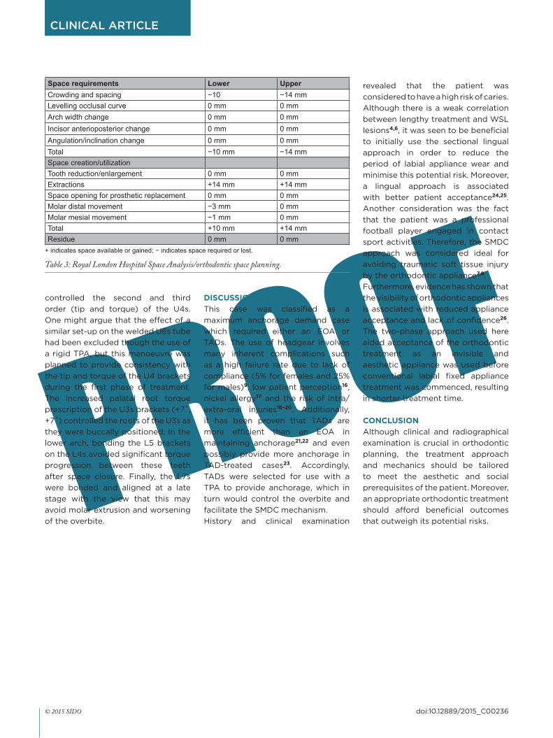
Treatment rationaleAs the patient’s Class II skeletal base discrepancy was mild, the orthodontic camouflage approach was considered appropriate. In view of Royal London Space Analysis14,15, the lower and upper arches were treated on an extraction basis (Table 3). Selection of the U5s was based primarily on their poor prognosis. From a biomechanical point of view, the TPA/TAD combination helped to maintain the anchorage and overbite.Concerning bracket prescription and set-up, self-ligating brackets were selected because of clinician convenience due to ease of ligation and patient comfort due to absence of wire ligatures palatally. Additionally, swapping and inverting the palatally bonded U4 self-ligation brackets
lower incisors were slightly retroclined and extruded, while the lower molars had moved mesially and extruded.
PrognosisThe prognosis for the stability of the occlusion was good, although it was anticipated that there would be some future growth, particularly vertically, which might reduce the overbite. Long-term wear of the upper and lower PFRs during the night was advocated if the patient wished to maintain archform as well as the alignment of the teeth. Although an upper bonded retainer might be preferable, the limited incisor clearance and consequently probable increased bonding failure led to its exclusion from the treatment plan.
tubes were bonded and treatment moved to the final stage. The final stage involved the use of bilateral settling zig-zag and anterior box elastics (3/8”, 3.5 oz) on an upper 0.019” × 0.025” SS and lower 0.014” SS archwire (Fig. 10). At debonding, a mere 7 months following placement of the full conventional fixed appliance, upper and lower PFR retainers were provided for night-time use only (Figs. 11 and 12).
Treatment changesThe patient was successfully treated using a two-phase approach over a period of 15 months. Satisfactory orthodontic outcomes were achieved, as reflected in the post-treatment IOTN and Peer Assessment Rating13 scores (Table 2).Towards the end of treatment, OPT and cephalometric analysis demonstrated very mild dental and skeletal changes as a result of treatment, growth changes and/or tracing error (Table 1, Figs. 13-15). Superimposition on Bjork’s stable maxillary structures revealed a mild proclination and extrusion of the upper incisors, possibly due to the effect of the settling elastics, whereas the upper molars were almost stable due to the use of the TPA/TADs combination. The mandibular superimposition confirmed that the
Almuzian M. • Sectional Cable Orthodontic Technique
Index Parameter ValueIOTNDental Health Component Start 4i
Finish 2gAesthetic Component Start 6
Finish 1PAR
Start 55Finish 2Change 53% Change 96.4%
Table 2: Occlusal indices.
Figure 14: Cephalogram and its tracing towards the end of treatment.
Figure 15: Cephalometric superimposition registered on: (A) the cranial base, and (B) maxillary and (C) mandibular Bjork’s stable structures.
A
B
C
IOTN: Index of Orthodontic Treatment Need; PAR: Peer Assessment Rating.
revealed that the patient was considered to have a high risk of caries. Although there is a weak correlation between lengthy treatment and WSL lesions4,6, it was seen to be beneficial to initially use the sectional lingual approach in order to reduce the period of labial appliance wear and minimise this potential risk. Moreover, a lingual approach is associated with better patient acceptance24,25. Another consideration was the fact that the patient was a professional football player engaged in contact sport activities. Therefore, the SMDC approach was considered ideal for avoiding traumatic soft tissue injury by the orthodontic appliance7,8.Furthermore, evidence has shown that the visibility of orthodontic appliances is associated with reduced appliance acceptance and lack of confidence26. The two-phase approach used here aided acceptance of the orthodontic treatment as an invisible and aesthetic appliance was used before conventional labial fixed appliance treatment was commenced, resulting in shorter treatment time.
CONCLUSIONAlthough clinical and radiographical examination is crucial in orthodontic planning, the treatment approach and mechanics should be tailored to meet the aesthetic and social prerequisites of the patient. Moreover, an appropriate orthodontic treatment should afford beneficial outcomes that outweigh its potential risks.
DISCUSSIONThis case was classified as a maximum anchorage demand case which required either an EOA or TADs. The use of headgear involves many inherent complications such as a high failure rate due to lack of compliance (5% for females and 25% for males)9, low patient perception16, nickel allergy17 and the risk of intra/extra-oral injuries18–20. Additionally, it has been proven that TADs are more efficient than an EOA in maintaining anchorage21,22 and even possibly provide more anchorage in TAD-treated cases23. Accordingly, TADs were selected for use with a TPA to provide anchorage, which in turn would control the overbite and facilitate the SMDC mechanism.History and clinical examination
controlled the second and third order (tip and torque) of the U4s. One might argue that the effect of a similar set-up on the welded U6s tube had been excluded though the use of a rigid TPA, but this manoeuvre was planned to provide consistency with the tip and torque of the U4 brackets during the first phase of treatment. The increased palatal root torque prescription of the U3s brackets (+7˚, +7˚) controlled the roots of the U3s as they were buccally positioned. In the lower arch, bonding the L5 brackets on the L4s avoided significant torque progression between these teeth after space closure. Finally, the L7s were bonded and aligned at a late stage with the view that this may avoid molar extrusion and worsening of the overbite.
Space requirements Lower UpperCrowding and spacing −10 −14 mmLevelling occlusal curve 0 mm 0 mmArch width change 0 mm 0 mmIncisor anterioposterior change 0 mm 0 mmAngulation/inclination change 0 mm 0 mmTotal −10 mm −14 mmSpace creation/utilizationTooth reduction/enlargement 0 mm 0 mmExtractions +14 mm +14 mmSpace opening for prosthetic replacement 0 mm 0 mmMolar distal movement −3 mm 0 mmMolar mesial movement −1 mm 0 mmTotal +10 mm +14 mmResidue 0 mm 0 mm
+ indicates space available or gained; − indicates space required or lost.
Table 3: Royal London Hospital Space Analysis/orthodontic space planning.
4. Gorelick L, Geiger AM, Gwinnett AJ. Incidence of white spot formation after bonding and banding. Am J Orthod 1982;81:93–98.
5. Zachrisson BU, Zachrisson S. Caries incidence and oral hygiene during orthodontic treatment. Eur J Oral Sci 1971;79:394–401.
6. Al Mulla AH, Kharsa SA, Kjellberg H, Birkhed D. Caries risk profiles in orthodontic patients at follow-up using Cariogram. Angle Orthod 2009;79:323–330.
7. Ellis PE, Benson PE. Potential hazards of orthodontic treatment–what your patient should know. Dent Update 2002;29:492–496.
8. Ngeow W, Kon L. Entrapped lip following sport injury. Dent Update 1997;24:285–286.
9. Ghafaria J, Shoferb F, Jacobsson-Hunta U, Markowitzc D, Lasterb L. Headgear versus function regulator in the early treatment of class II, division 1 malocclusion: a randomized clinical trial. Am J Orthod Dentofac Orthop 1998;113:51–61.
10. Baek S-H, Kim B-M, Kyung S-H, Lim JK, Kim YH. Success rate and risk factors associated with mini-implants reinstalled in the maxilla. Angle Orthod 2008;78:895–901.
11. Cousley RR. A clinical strategy for maxillary molar intrusion using orthodontic mini implants and a customized palatal arch. J Orthod 2010;37:202–208.
12. Ohashi E, Pecho OE, Moron M, Lagravere MO. Implant vs screw loading protocols in orthodontics: a systematic review. Angle Orthod 2006;76:721–727.
13. Parbatani R, Williams A, Ireland A, Sandy J. The process of orthognathic care in an NHS region. Annals RCS Eng 2010;92:34.
14. Kirschen RH, O’Higgins EA, Lee RT. The Royal London Space Planning: an integration of space analysis and treatment planning: Part I: Assessing the space required to meet treatment objectives. Am J Orthod Dentofac Orthop 2000;118:448–455.
15. Kirschen RH, O’Higgins EA, Lee RT. The Royal London Space Planning: an integration of space analysis and treatment planning: Part II: The effect of other treatment procedures on space. Am J Orthod Dentofac Orthop 2000;118:456–461.
16. Sandler J. A comparison of the effectiveness of three methods of anchorage reinforcement in the treatment of maximum anchorage patients–a randomised clinical trial. PhD thesis, University of Sheffield, 2014.
17. Rahilly G, Price N. Current products and practice: nickel allergy and orthodontics. J Orthod 2003;30:171–174.
18. Booth-Mason S, Birnie D. Penetrating eye injury from orthodontic headgear–a case report. Eur J Orthod 1988;10:111–114.
19. Holland GN, Wallace DA, Mondino BJ, Cole SH, Ryan SJ. Severe ocular injuries from orthodontic headgear. Arch Ophthalmol 1985;103:649–651.
20. Samuels RH, Jones ML. Orthodontic facebow injuries and safety equipment. Eur J Orthod 1994;16:385–394.
21. Feldmann I, Bondemark L. Orthodontic anchorage: a systematic review. Angle Orthod 2006;76:493–501.
22. Ma J, Wang L, Zhang W, Chen W, Zhao C, Smales RJ. Comparative evaluation of micro-implant and headgear anchorage used with a pre-adjusted appliance system. Eur J Orthod 2008;30:283–287.
23. Al-Sibaie S, Hajeer MY. Assessment of changes following en-masse retraction with mini-implants anchorage compared to two-step retraction with conventional anchorage in patients with class II division 1 malocclusion: a randomized controlled trial. Eur J Orthod 2014;36:275–283.
24. Fritz U, Diedrich P, Wiechmann D. Lingual technique–patients’ characteristics, motivation and acceptance. Interpretation of a retrospective survey. J Orofac Orthop 2002;63:227–233.
25. Romano R. Lingual Orthodontics. Hamilton: B.C. Decker, 1998.
26. Sergl HG, Klages U, Zentner A. Functional and social discomfort during orthodontic treatment–effects on compliance and prediction of patients’ adaptation by personality variables. Eur J Orthod 2000;22:307–315.