128
Modified Fall 2007 Santa Barbara City College ENGR/DRAFT 105 Packet Engineering Graphics Nick Arnold
| Date post: | 30-Mar-2018 |
| Category: |
Documents |
| Upload: | nguyenhanh |
| View: | 216 times |
| Download: | 2 times |
Modified Fall 2007
Santa Barbara City College
ENGR/DRAFT 105 Packet
Engineering Graphics
Nick Arnold


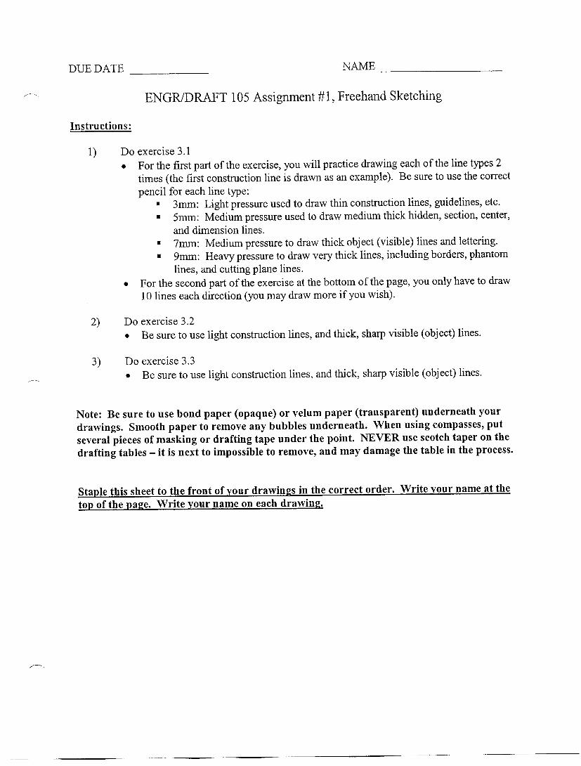


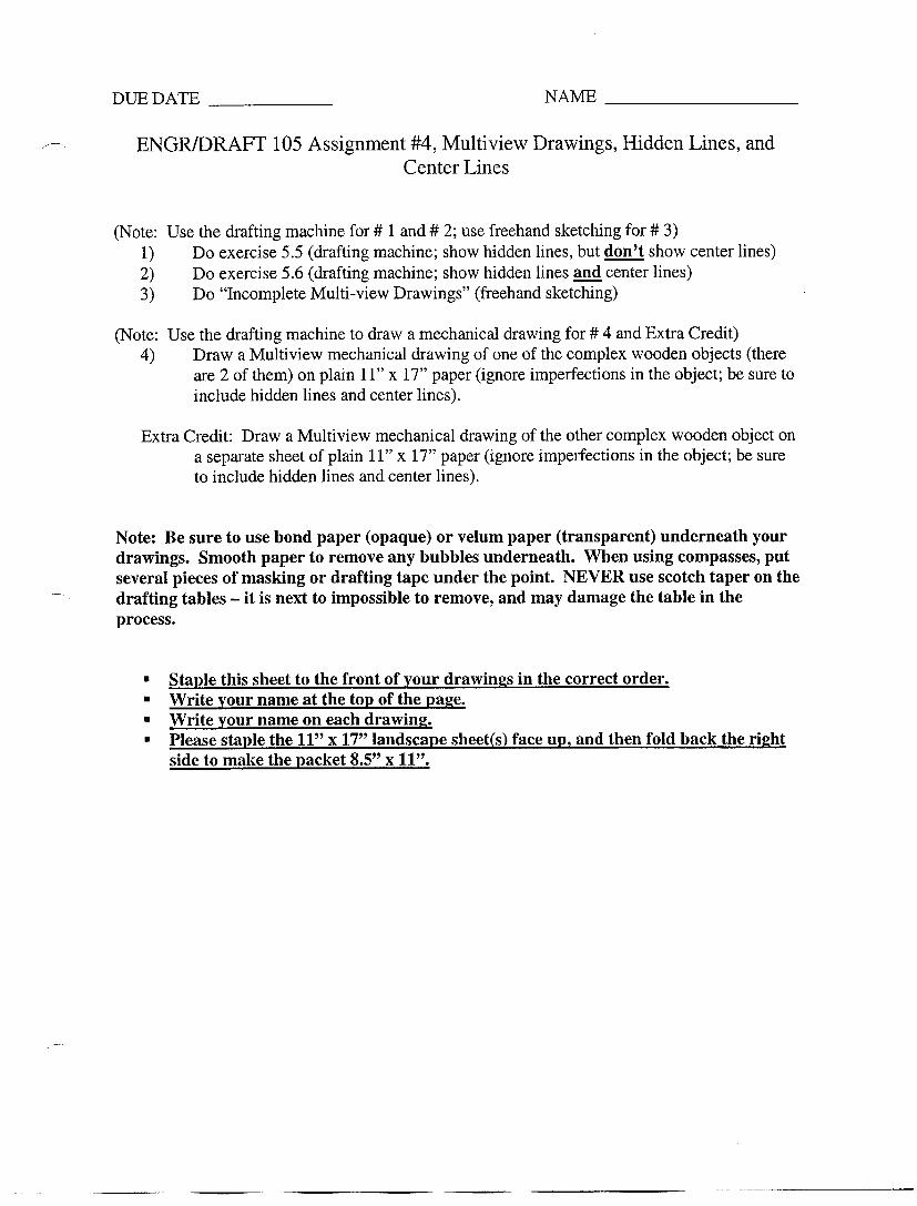


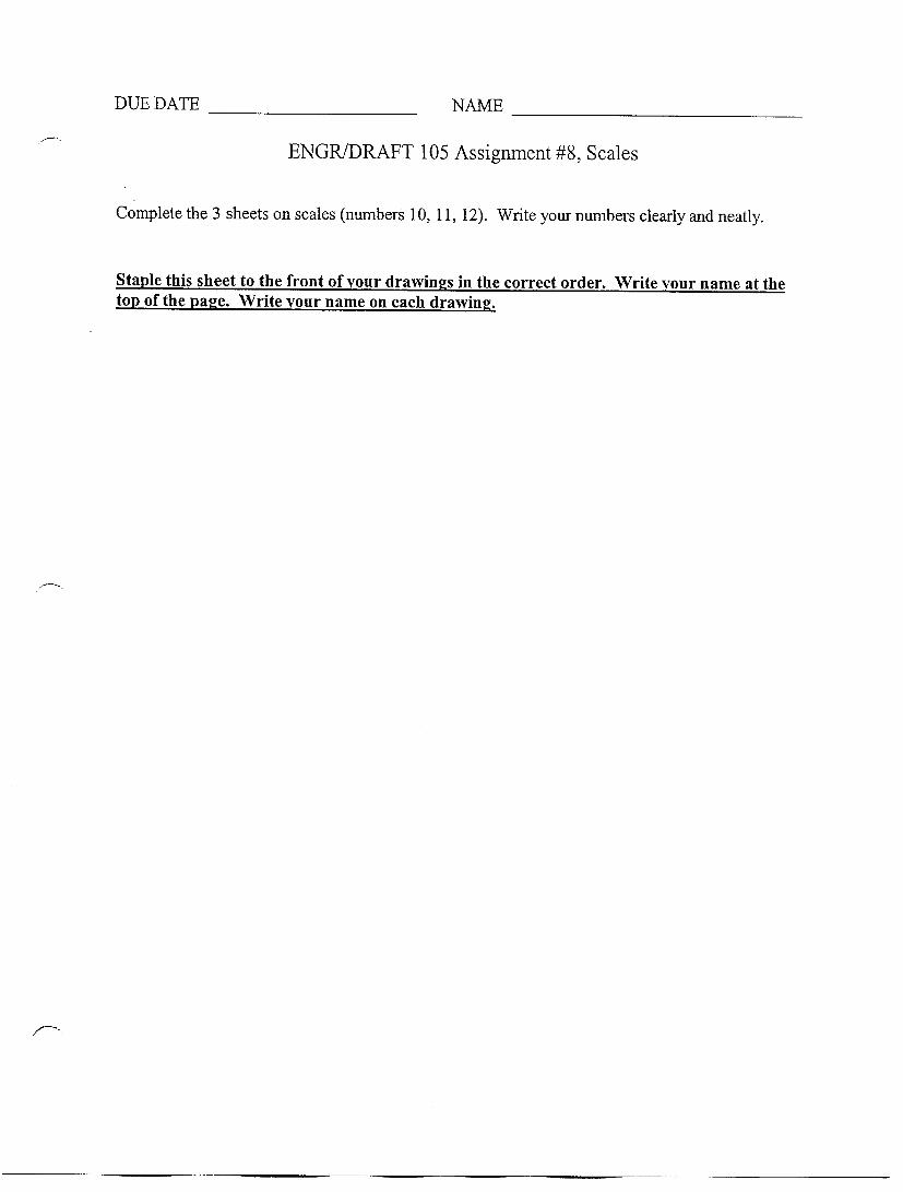
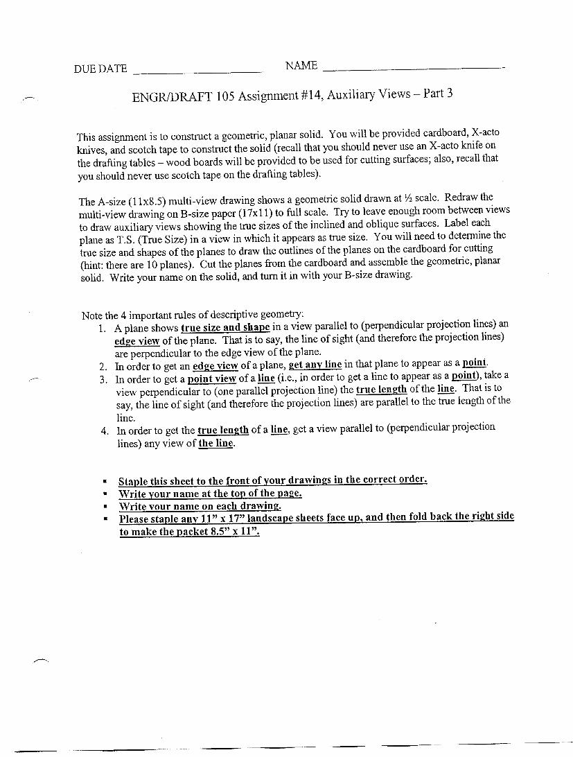
DUE DATE ______________ NAME ______________________
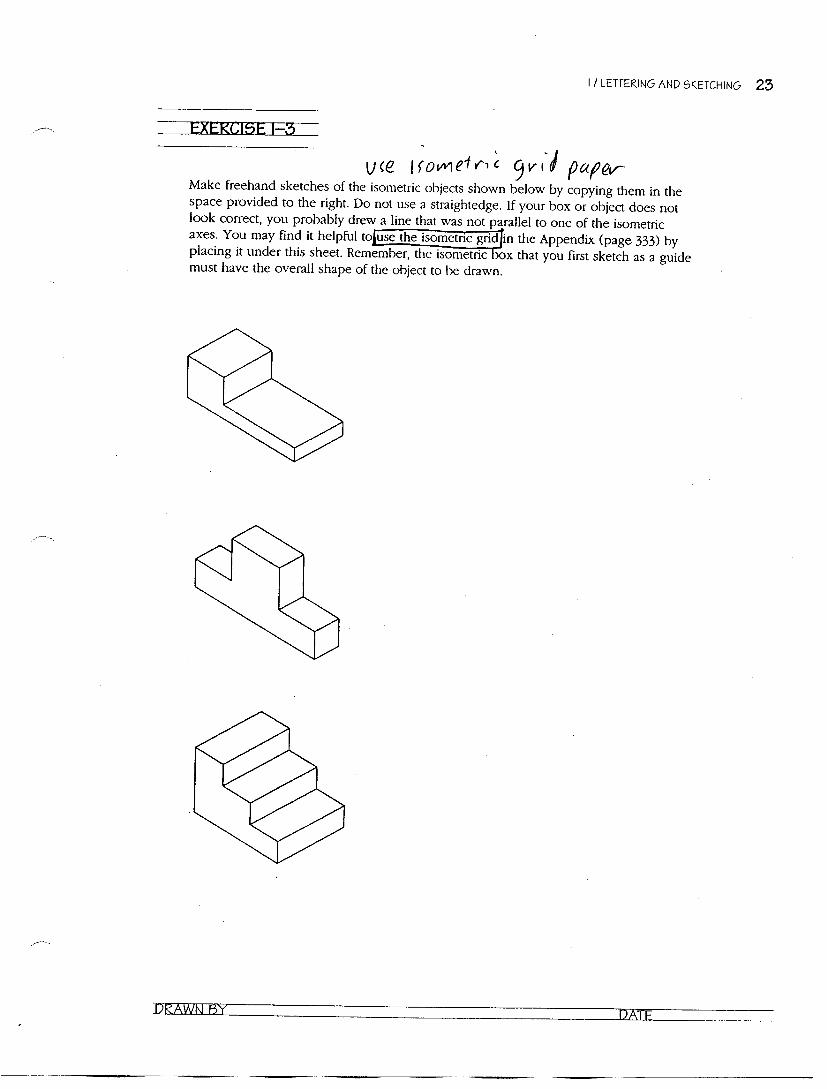
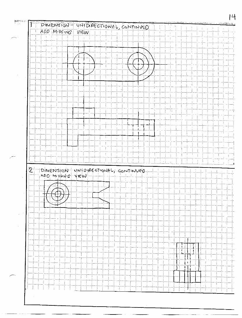
ENGR/DRAFT 105 Assignment #5, Isometric Pictorials (Note: Use freehand sketching for all drawings for this assignment)
1) Do exercise 1-3 (not in textbook) 2) Do exercise 1-4 (not in textbook) 3) Do exercise 1-5 (not in textbook)
(Note: Use the drafting machine to draw a mechanical drawing for # 4 and 5)
4) Draw an isometric mechanical drawing of model #1 (L-shaped wood object with hole – ignore imperfections in the object) on plain 8 ½” x 11” paper.
5) Draw an isometric mechanical drawing of model #2 (clay object in plastic cube – ignore imperfections in the object; please orient the whole on the front plane of the object and exaggerate the size of the whole to clearly show the elliptical shape) on plain 8 ½” x 11” paper.
! Staple this sheet to the front of your drawings in the correct order. ! Write your name at the top of the page. ! Write your name on each drawing. ! Please staple the 11” x 17” landscape sheet(s) face up, and then fold back the right side
to make the packet 8.5” x 11”.


DUE DATE ________________________ NAME __________________________________
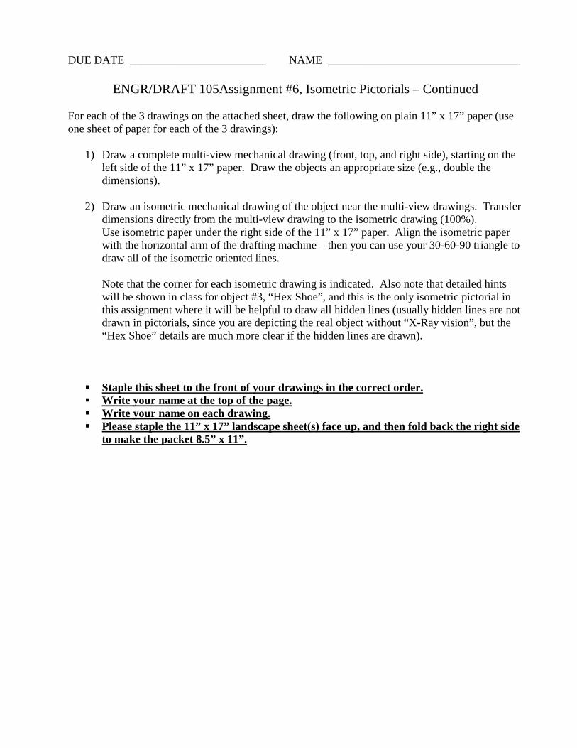
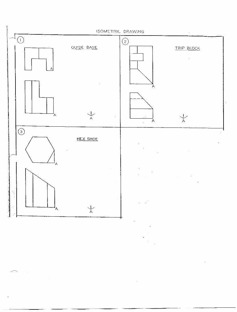
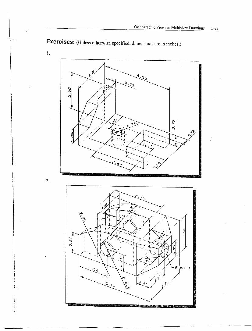
ENGR/DRAFT 105Assignment #6, Isometric Pictorials – Continued
For each of the 3 drawings on the attached sheet, draw the following on plain 11” x 17” paper (use one sheet of paper for each of the 3 drawings):
1) Draw a complete multi-view mechanical drawing (front, top, and right side), starting on the left side of the 11” x 17” paper. Draw the objects an appropriate size (e.g., double the dimensions).
2) Draw an isometric mechanical drawing of the object near the multi-view drawings. Transfer
dimensions directly from the multi-view drawing to the isometric drawing (100%). Use isometric paper under the right side of the 11” x 17” paper. Align the isometric paper with the horizontal arm of the drafting machine – then you can use your 30-60-90 triangle to draw all of the isometric oriented lines. Note that the corner for each isometric drawing is indicated. Also note that detailed hints will be shown in class for object #3, “Hex Shoe”, and this is the only isometric pictorial in this assignment where it will be helpful to draw all hidden lines (usually hidden lines are not drawn in pictorials, since you are depicting the real object without “X-Ray vision”, but the “Hex Shoe” details are much more clear if the hidden lines are drawn).
! Staple this sheet to the front of your drawings in the correct order. ! Write your name at the top of the page. ! Write your name on each drawing. ! Please staple the 11” x 17” landscape sheet(s) face up, and then fold back the right side
to make the packet 8.5” x 11”.


DUE DATE ________________________ NAME __________________________________
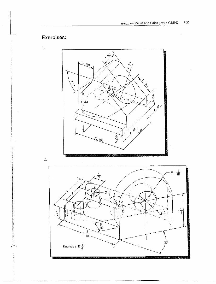
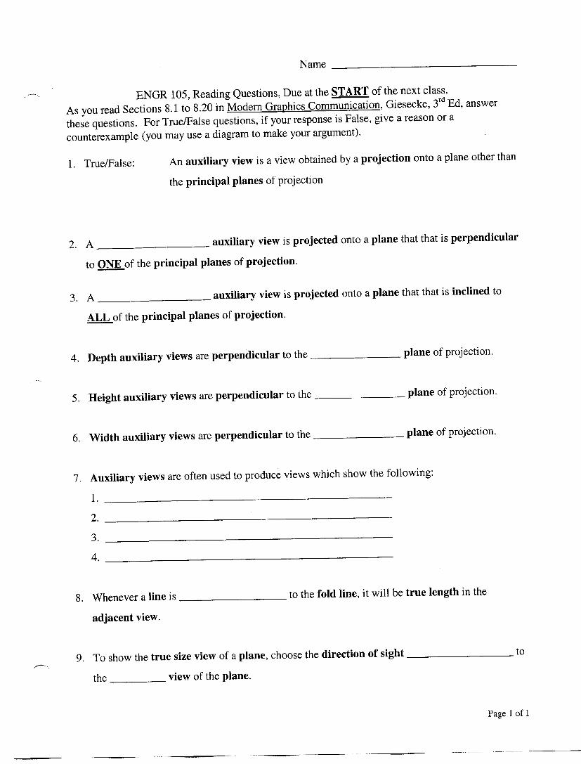
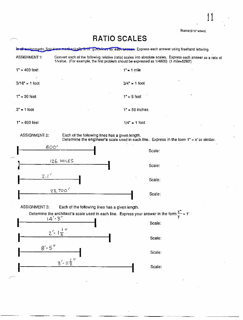
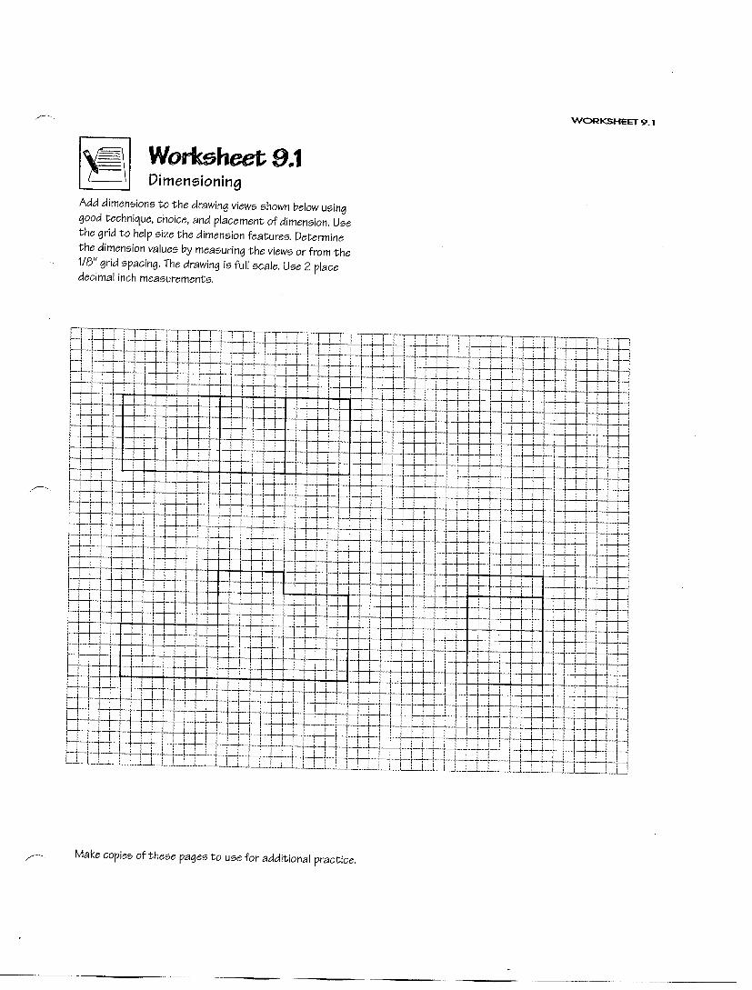
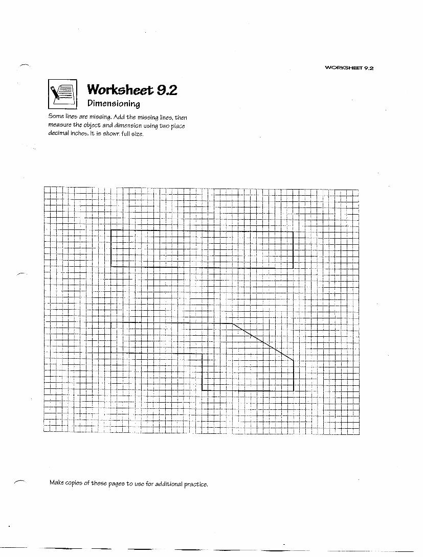
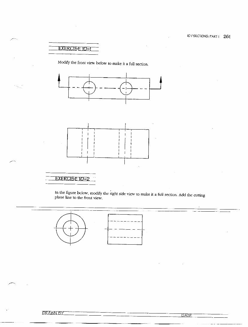
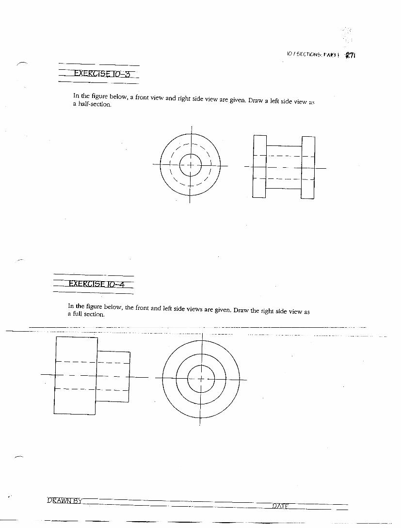
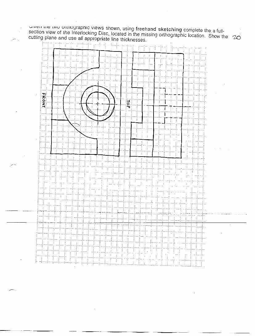
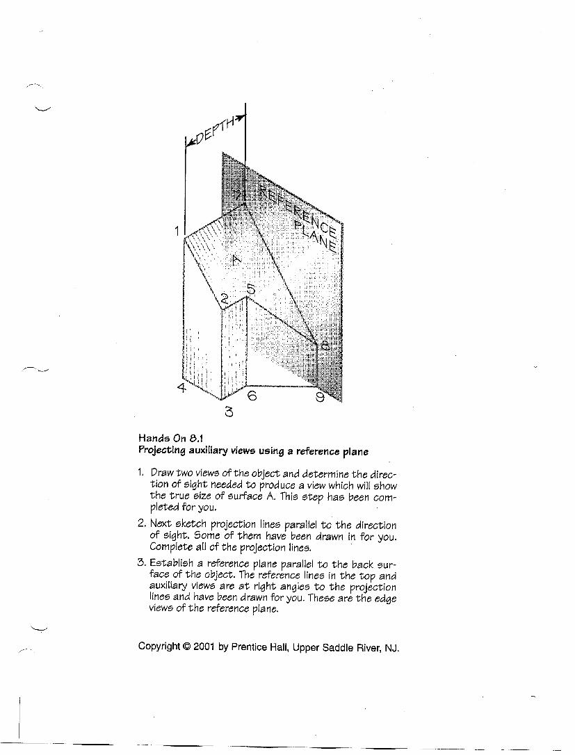
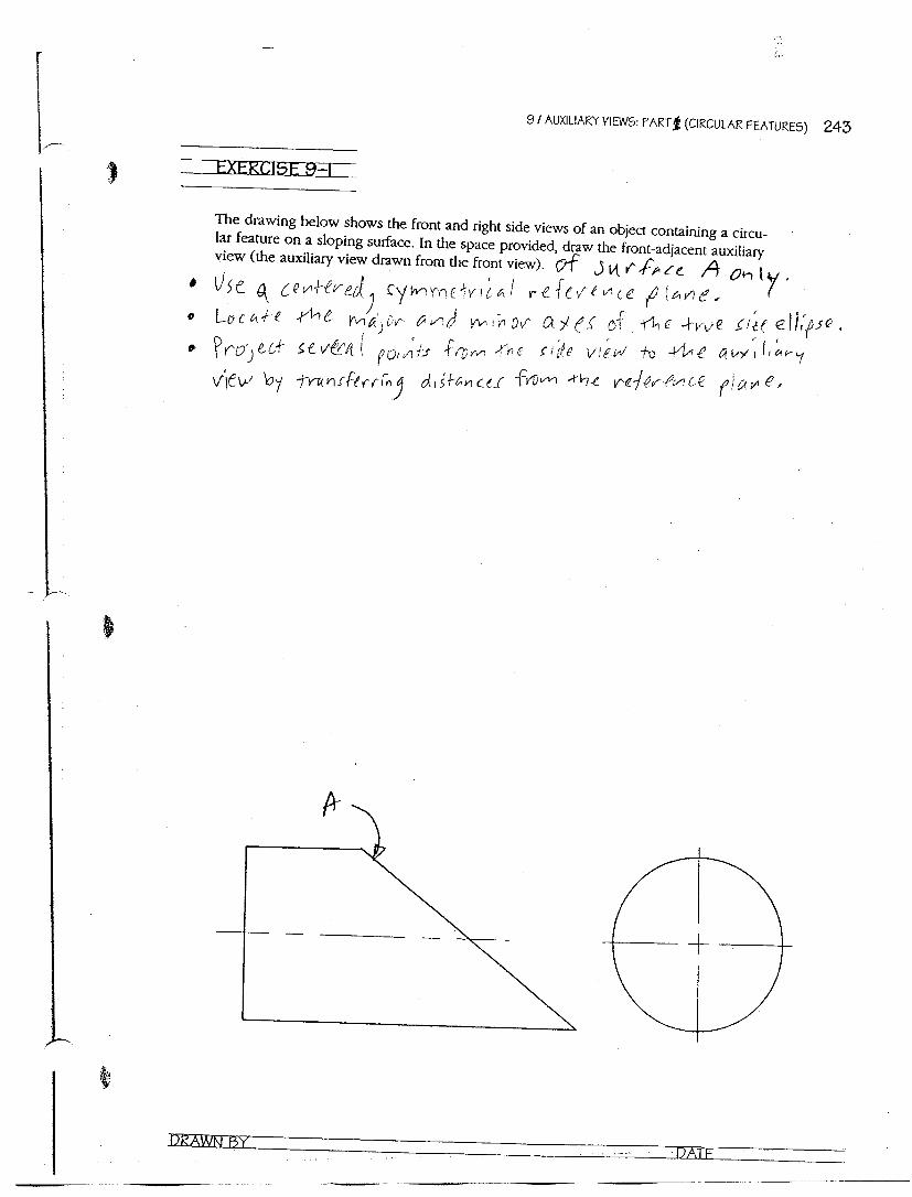
ENGR/DRAFT 105 Assignment #12, Auxiliary Views – Part 1
Draw mechanically the 3 auxiliary view assignments listed below: • Sheet labeled “Exercises 8.1 & 8.2” • Sheet labeled “Exercise 9.1” • Sheet labeled “Exercise 9.4”
Note the 2 important rules of Auxiliary Views:
1. Adjacent Views share projection lines. 2. Alternate views share distances from reference planes (or fold lines).
Note the 4 important rules of Descriptive Geometry:
1. A plane shows true size and shape in a view parallel to (perpendicular projection lines) an edge view of the plane. That is to say, the line of sight (and therefore the projection lines) are perpendicular to the edge view of the plane.
2. In order to get an edge view of a plane, get any line in that plane to appear as a point. 3. In order to get a point view of a line (i.e., in order to get a line to appear as a point), take a
view perpendicular to (one parallel projection line) the true length of the line. That is to say, the line of sight (and therefore the projection lines) are parallel to the true length of the line.
4. In order to get the true length of a line, get a view parallel to (perpendicular projection lines) any view of the line.
Staple this sheet to the front of your drawings in the correct order. Write your name at the top of the page. Write your name on each drawing.


DUE DATE ________________________ NAME __________________________________
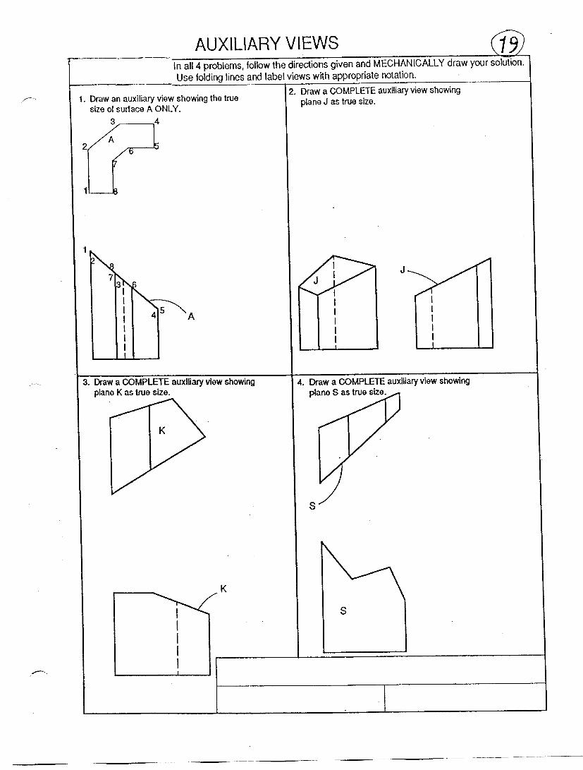
ENGR/DRAFT 105 Assignment #13, Auxiliary Views – Part 2
Draw mechanically the 3 auxiliary view assignments (Plates 19, 26, and 27). Note the 2 important rules of Auxiliary Views:
1. Adjacent Views share projection lines. 2. Alternate views share distances from reference planes (or fold lines).
Note the 4 important rules of descriptive geometry:
1. A plane shows true size and shape in a view parallel to (perpendicular projection lines) an edge view of the plane. That is to say, the line of sight (and therefore the projection lines) are perpendicular to the edge view of the plane.
2. In order to get an edge view of a plane, get any line in that plane to appear as a point. 3. In order to get a point view of a line (i.e., in order to get a line to appear as a point), take a
view perpendicular to (one parallel projection line) the true length of the line. That is to say, the line of sight (and therefore the projection lines) are parallel to the true length of the line.
4. In order to get the true length of a line, get a view parallel to (perpendicular projection lines) any view of the line.
Staple this sheet to the front of your drawings in the correct order. Write your name at the top of the page. Write your name on each drawing.


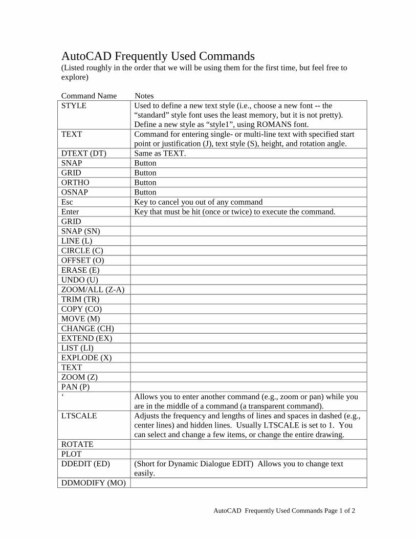
AutoCAD Frequently Used Commands Page 1 of 2
AutoCAD Frequently Used Commands (Listed roughly in the order that we will be using them for the first time, but feel free to explore) Command Name Notes STYLE Used to define a new text style (i.e., choose a new font -- the
“standard” style font uses the least memory, but it is not pretty). Define a new style as “style1”, using ROMANS font.
TEXT Command for entering single- or multi-line text with specified start point or justification (J), text style (S), height, and rotation angle.
DTEXT (DT) Same as TEXT. SNAP Button GRID Button ORTHO Button OSNAP Button Esc Key to cancel you out of any command Enter Key that must be hit (once or twice) to execute the command. GRID SNAP (SN) LINE (L) CIRCLE (C) OFFSET (O) ERASE (E) UNDO (U) ZOOM/ALL (Z-A) TRIM (TR) COPY (CO) MOVE (M) CHANGE (CH) EXTEND (EX) LIST (LI) EXPLODE (X) TEXT ZOOM (Z) PAN (P) ‘ Allows you to enter another command (e.g., zoom or pan) while you
are in the middle of a command (a transparent command). LTSCALE Adjusts the frequency and lengths of lines and spaces in dashed (e.g.,
center lines) and hidden lines. Usually LTSCALE is set to 1. You can select and change a few items, or change the entire drawing.
ROTATE PLOT DDEDIT (ED) (Short for Dynamic Dialogue EDIT) Allows you to change text
easily. DDMODIFY (MO)

AutoCAD Frequently Used Commands Page 2 of 2
MTEXT (Short for Multi TEXT) Allows you to write text in a prescribed box, and writes multiple lines of text.
PLINE (PL) Polygon line PEDIT (PE) Allows you to edit a PLINE QDIM Quick Dimensioning STRETCH (S) FILLET (F) CHAMFER (CHA) BREAK (BR) VIEWRES Circles on the screen may not look round (but will be plotted round) –
use this command and change to a higher number (usually 2000 works well). Answer YES when asked if you want quick zoom.
DDIM (D) (Short for Dimension Style Manager) Choose NEW when changing dimensioning – don’t change the Standard.
DIMCEN Easy way to draw centerlines for small holes or arcs (set it to –0.9; default is +0.9)
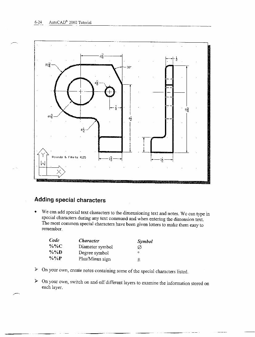
CEN DCE DIVIDE ARRAY (AR) HATCH (H) MIRROR (MI) MIRRTEXT Special Characters / Text Modifiers (note that the command MTEXT has a list of special characters) %%d Degree symbol %%c Diameter symbol %%p Plus/minus symbol %%% Percent symbol %%u Starts/stops underlining %%o Starts/stops overlining Note: To get special characters, select MTEXT --> SYMBOL (@) --> OTHER, and the change the font to GDT.


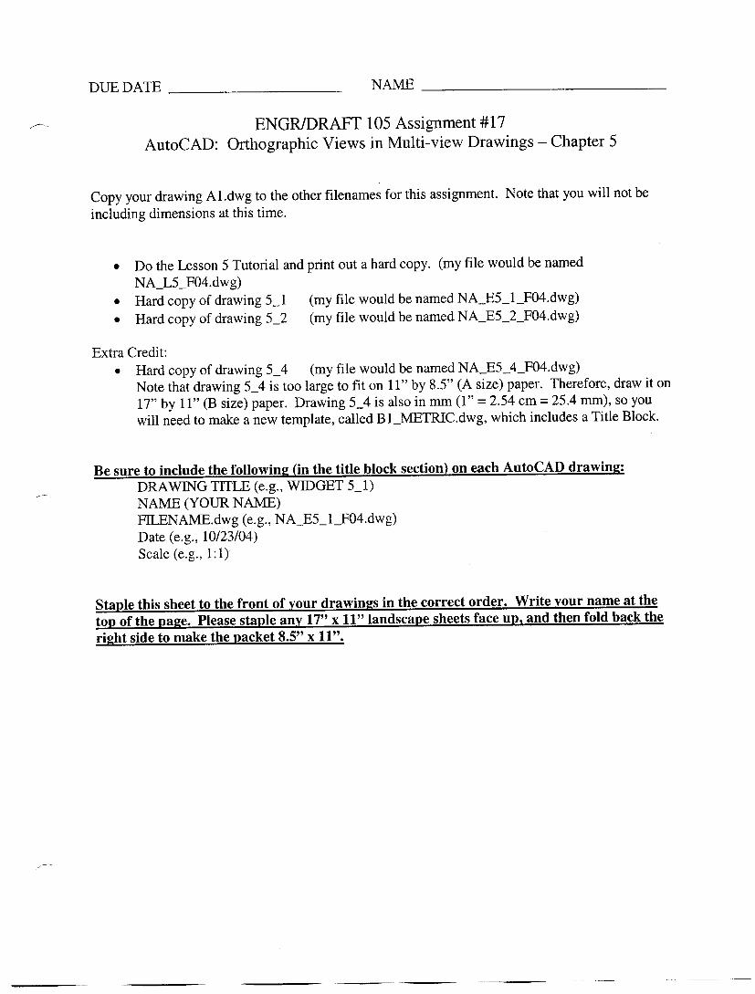


DUE DATE ________________________ NAME __________________________________
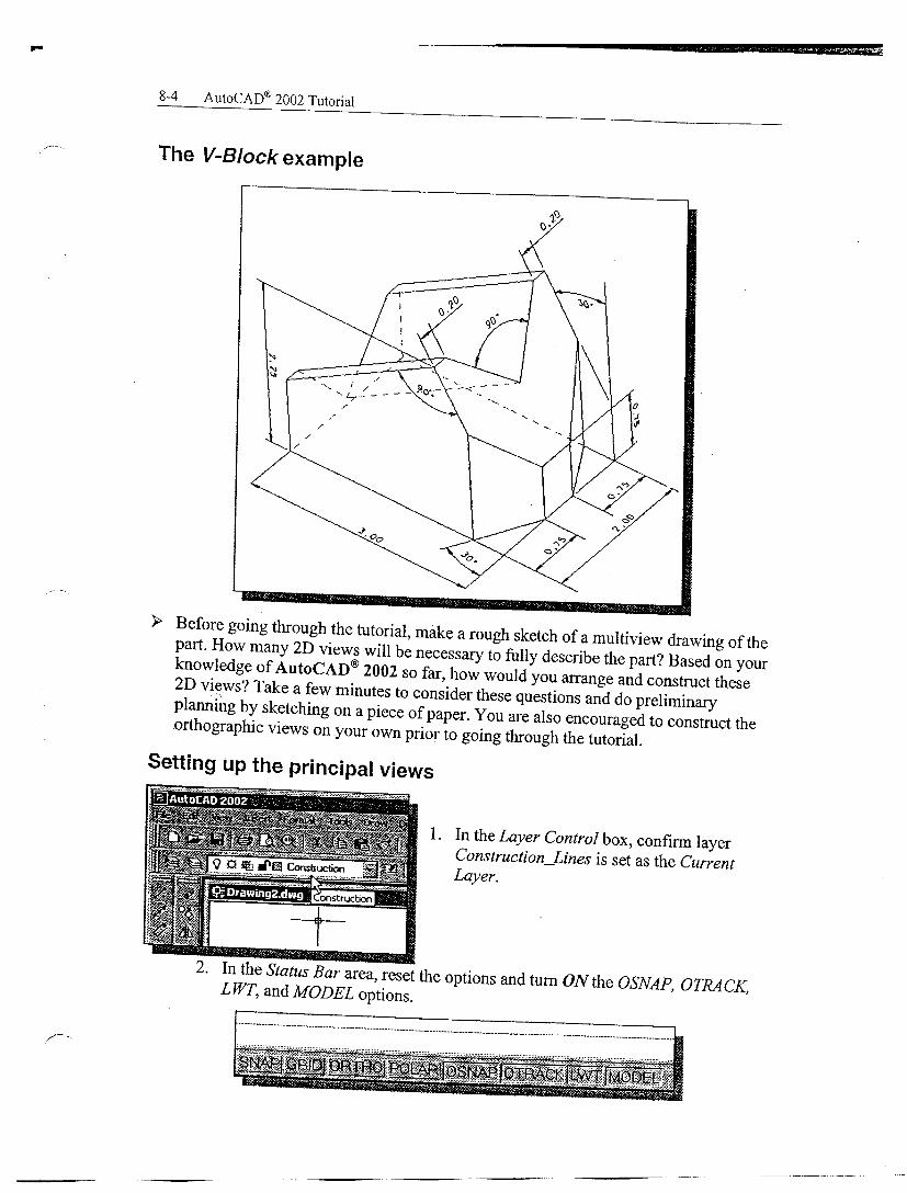
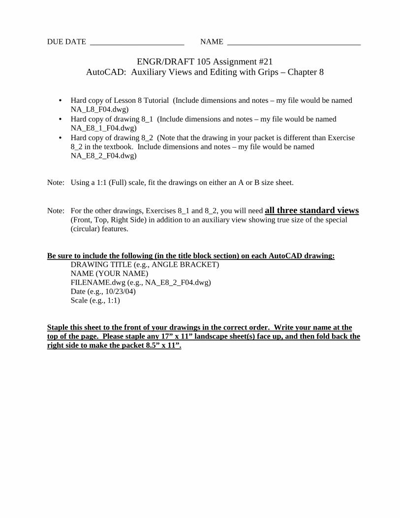
ENGR/DRAFT 105 Assignment #21 AutoCAD: Auxiliary Views and Editing with Grips – Chapter 8
• Hard copy of Lesson 8 Tutorial (Include dimensions and notes – my file would be named NA_L8_F04.dwg)
• Hard copy of drawing 8_1 (Include dimensions and notes – my file would be named NA_E8_1_F04.dwg)
• Hard copy of drawing 8_2 (Note that the drawing in your packet is different than Exercise 8_2 in the textbook. Include dimensions and notes – my file would be named NA_E8_2_F04.dwg)
Note: Using a 1:1 (Full) scale, fit the drawings on either an A or B size sheet. Note: For the other drawings, Exercises 8_1 and 8_2, you will need all three standard views
(Front, Top, Right Side) in addition to an auxiliary view showing true size of the special (circular) features.
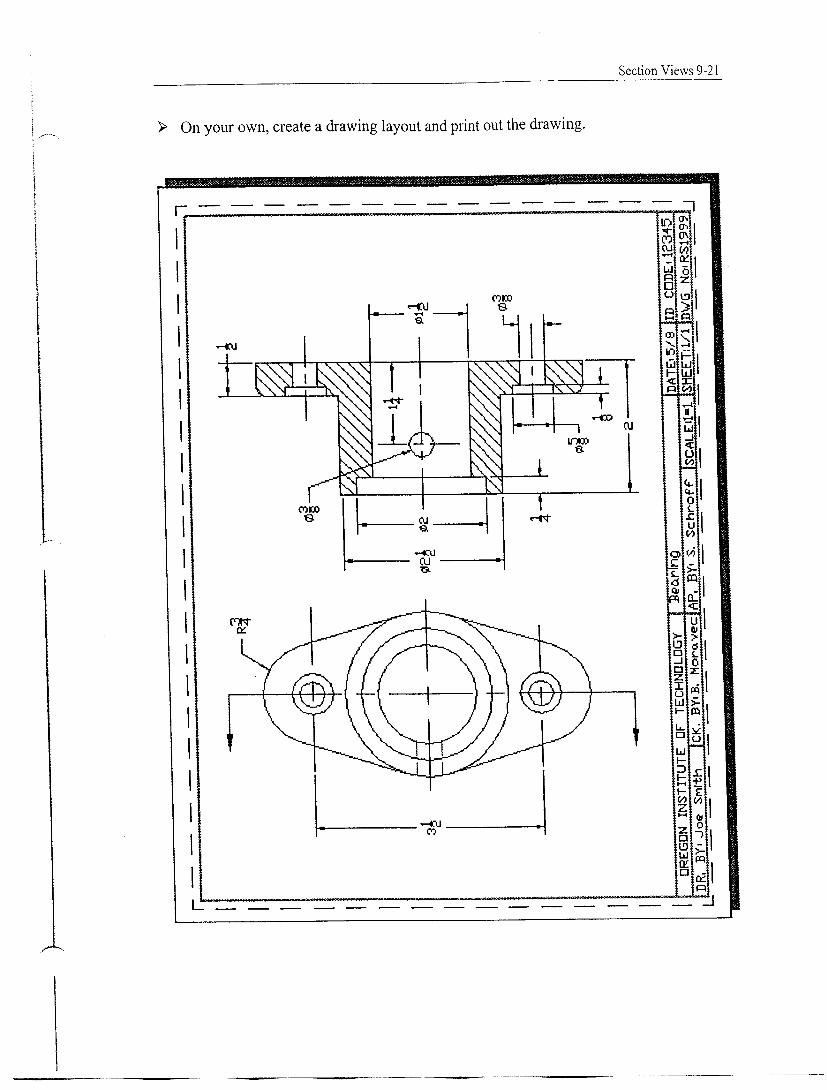
Be sure to include the following (in the title block section) on each AutoCAD drawing: DRAWING TITLE (e.g., ANGLE BRACKET)
NAME (YOUR NAME) FILENAME.dwg (e.g., NA_E8_2_F04.dwg) Date (e.g., 10/23/04) Scale (e.g., 1:1)
Staple this sheet to the front of your drawings in the correct order. Write your name at the top of the page. Please staple any 17” x 11” landscape sheet(s) face up, and then fold back the right side to make the packet 8.5” x 11”.