20
Modified Proctor/Fagerberg Method for Coal 24th November 2014 1 of 20 Modified Proctor/Fagerberg Method for Coal

Modified Proctor/Fagerberg Method for Coal
24th November 2014 1 of 20
Modified Proctor/Fagerberg Method for Coal

Modified Proctor/Fagerberg Method for Coal
24th November 2014 2 of 20
Contents Page
1 Scope .......................................................................................................................................................3
2 Normative References .............................................................................................................................3
3 Definitions ................................................................................................................................................4 3.1 Transportable Moisture Limit (TML) .........................................................................................................4 3.2 Test Outcomes .........................................................................................................................................4 3.3 Optimum Moisture Content (OMC) ..........................................................................................................4 3.4 Gross Water Content or Total Moisture (W1) ...........................................................................................4
4 Apparatus .................................................................................................................................................4 4.1 Work Area ................................................................................................................................................4 4.2 Standard Sieves .......................................................................................................................................4 4.3 Proctor/Fagerberg apparatus ...................................................................................................................4 4.4 Compaction hammer ...............................................................................................................................5 4.5 Drying oven ..............................................................................................................................................5 4.6 Weighing balance ....................................................................................................................................5 4.7 Pycnometer ..............................................................................................................................................5 4.8 Containers for hand mixing and sample preparation ...............................................................................6 4.9 Flat Scraping Device ................................................................................................................................6 4.10 Drying trays ..............................................................................................................................................6 4.11 Spray bottle ..............................................................................................................................................6 4.12 Gloves ......................................................................................................................................................6 4.13 Sample Divider .........................................................................................................................................6
5 Sampling and Sample Preparation ..........................................................................................................7 5.1 General ....................................................................................................................................................7 5.2 Sample preparation .................................................................................................................................7 5.2.1 Sample homogenisation and division ......................................................................................................7 5.2.2 Reconstituted Sample Preparation Procedure ........................................................................................7 5.2.3 As received moisture ...............................................................................................................................8 5.2.4 Particle density measurement .................................................................................................................9
6 Proctor/Fagerberg Test Procedure ..........................................................................................................9 6.1 Variables and definitions ..........................................................................................................................9 6.2 Establishment of the initial compaction point .........................................................................................11 6.3 Establishment of complete compaction curve .......................................................................................12 6.4 Visual appearance of coal in the test cell ..............................................................................................13 6.5 Calculation of key parameters for determination of compaction curve ..................................................14 6.6 Presentation of compaction results ........................................................................................................15 6.7 Sample compaction curve .....................................................................................................................16 6.8 Determination of transportable moisture limit ........................................................................................17 6.8.1 Determination of PFD70 Moisture Content ............................................................................................17 6.8.2 Cases where the highest determinable point on the compaction curve lies below 70% saturation ......17
7 Test Report ............................................................................................................................................17
Annex A Example of a Proctor/Fagerberg Apparatus ........................................................................................19

Modified Proctor/Fagerberg Method for Coal
24th November 2014 3 of 20
1 Scope
This procedure details the laboratory determination of Transportable Moisture Limit (TML) for coals up to a nominal top size of 50 mm. The procedure is based on a modification of the Proctor/Fagerberg test for general bulk materials described in Appendix 2 of the International Maritime Solid Bulk Cargoes (IMSBC) Code.
Key modifications to the original test contained in the IMSBC Code are:
Sample preparation to facilitate the testing of 0 x 50 mm coal through reconstitution to -25 mm; Use of a 150 mm diameter test cell; and Sample compaction using a hammer equivalent to the Proctor/Fagerberg “D” energy hammer.
The Transportable Moisture Limit is the moisture content corresponding to the intersection of the 70% degree saturation curve and the test sample compaction curve.
In the case of coals where moisture freely drains from the sample such that the test sample compaction curve does not extend to or beyond 70% saturation, the test is taken to indicate a cargo where water passes through the spaces between particles and there is no increase in pore water pressure. Therefore, the cargo is not liable to liquefy (Reference: IMSBC Code s7.2.2).
The procedure commences with a drum of coal containing a sample of approximately 150 kg delivered to the testing laboratory and terminates with the laboratory reporting the test result for the coal. Details of the sample collection process are excluded from this procedure and reference should be made to the normative reference list below.
2 Normative References
The following documents are referenced in this procedure. For dated references, only the cited edition applies. For undated references, the latest edition of the referenced document (including any amendments) applies.
AS 1152:1993, Specification for test sieves
ISO 589:2008, Hard Coal - Determination of total moisture
AS 1289.3.5.1, Methods of testing soils for engineering purposes. Method 3.5.1: Soil classification tests – Determination of the soil particle density of a soil – Standard method.
AS 4264.1, Coal – Sampling procedures
AS 4264.4, Coal and Coke – Determination of precision and bias
AS 2418, Coal and Coke – Glossary of terms
IMSBC Code (2009), International maritime solid bulk cargoes code, International Maritime Organization.

Modified Proctor/Fagerberg Method for Coal
24th November 2014 4 of 20
3 Definitions
For the purpose of this document, the definitions given in “AS 2418, Coal and Coke – Glossary of terms” as well as those given below apply.
3.1 Transportable Moisture Limit (TML)
The transportable moisture limit (TML) of a cargo which may liquefy means the maximum moisture content of the cargo which is considered safe for carriage in ships not complying with the special provisions of sub-section 7.3.2 of the IMSBC Code for specially constructed or fitted cargo ships.
3.2 Test Outcomes
The TML determined by this procedure is the moisture content corresponding to the intersection of the 70% degree saturation curve and the test sample compaction curve, as described in this document. This is also referred to as the PFD70 value (Proctor/Fagerberg – D energy hammer – 70% saturation).
Where moisture freely drains from the sample or test cell at a moisture content such that the test sample compaction curve does not extend to or beyond 70% saturation (as described in section 6.4), the test is taken to indicate a cargo where water passes through the spaces between particles and there is no increase in pore water pressure. Therefore, the cargo is not liable to liquefy (Reference: IMSBC Code s7.2.2).
3.3 Optimum Moisture Content (OMC)
The optimum moisture content corresponds to the maximum compaction (maximum dry density) under the specified compaction condition.
3.4 Gross Water Content or Total Moisture (W1)
The moisture content of a sample is calculated as the mass of water divided by the total mass of solids plus water and is referred to as either the gross water content or the total moisture content. Gross water content is to be determined using the method for determining total moisture defined in the standard ISO 589.
4 Apparatus
4.1 Work Area
The work area must be located where the samples are protected from excessive temperatures, air currents and humidity variations. All phases of the material preparation and testing procedure shall be accomplished in a reasonable time to minimize moisture losses. All suitable sample containers, including plastic sample bags, shall be sealed.
4.2 Standard Sieves
Square aperture laboratory sieves of 16 and 25 mm aperture as nominated in AS 1152:1993 are required for reconstitution of the sample at 25 mm top size. A 2.36 mm sieve is required for generation of +2.36 mm and –2.36 mm fractions for particle density determination. Optionally a 2 mm sieve may be used for this purpose.
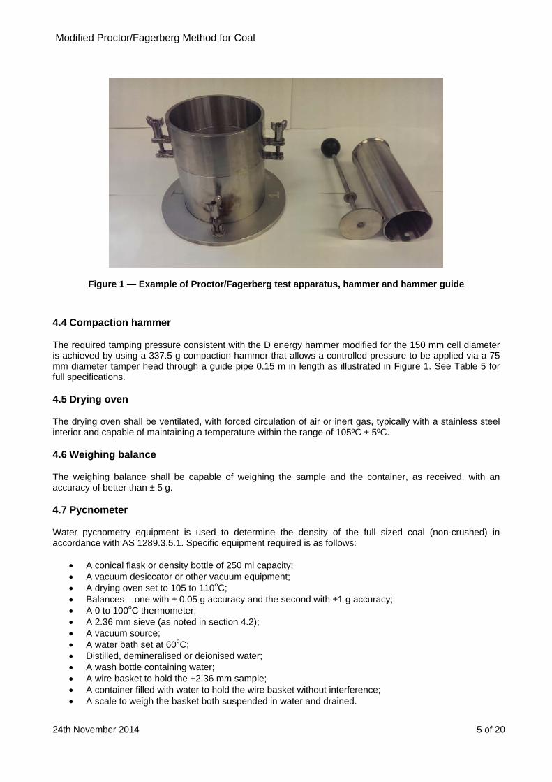
4.3 Proctor/Fagerberg apparatus
The Proctor/Fagerberg apparatus consists of a cylindrical stainless steel mould 150 mm in diameter and 120 mm high with a removable extension piece (the compaction cylinder) and a compaction tool guided by a pipe at its lower end (the compaction hammer), which is shown in Figure 1.
A schematic diagram of the Proctor/Fagerberg apparatus, including dimensions and tolerances in Table 5, is provided in Annex A.
Modified Proctor/Fagerberg Method for Coal
24th November 2014 5 of 20
Figure 1 — Example of Proctor/Fagerberg test apparatus, hammer and hammer guide
4.4 Compaction hammer
The required tamping pressure consistent with the D energy hammer modified for the 150 mm cell diameter is achieved by using a 337.5 g compaction hammer that allows a controlled pressure to be applied via a 75 mm diameter tamper head through a guide pipe 0.15 m in length as illustrated in Figure 1. See Table 5 for full specifications.
4.5 Drying oven
The drying oven shall be ventilated, with forced circulation of air or inert gas, typically with a stainless steel interior and capable of maintaining a temperature within the range of 105ºC ± 5ºC.
4.6 Weighing balance
The weighing balance shall be capable of weighing the sample and the container, as received, with an accuracy of better than ± 5 g.
4.7 Pycnometer
Water pycnometry equipment is used to determine the density of the full sized coal (non-crushed) in accordance with AS 1289.3.5.1. Specific equipment required is as follows:
A conical flask or density bottle of 250 ml capacity; A vacuum desiccator or other vacuum equipment; A drying oven set to 105 to 110oC; Balances – one with ± 0.05 g accuracy and the second with ±1 g accuracy; A 0 to 100oC thermometer; A 2.36 mm sieve (as noted in section 4.2); A vacuum source; A water bath set at 60oC; Distilled, demineralised or deionised water; A wash bottle containing water; A wire basket to hold the +2.36 mm sample; A container filled with water to hold the wire basket without interference; A scale to weigh the basket both suspended in water and drained.
Modified Proctor/Fagerberg Method for Coal
24th November 2014 6 of 20
4.8 Containers for hand mixing and sample preparation
Sufficient heavy-duty plastic buckets with lids of not less than 10 litres capacity are required for storage and handling.
Heavy-duty plastic bags (200 micron thick or greater) are required for storage and hand mixing of samples.
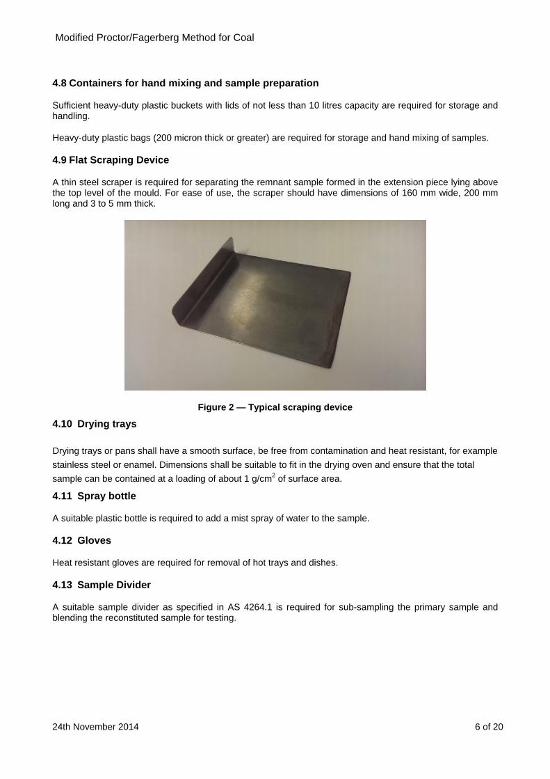
4.9 Flat Scraping Device
A thin steel scraper is required for separating the remnant sample formed in the extension piece lying above the top level of the mould. For ease of use, the scraper should have dimensions of 160 mm wide, 200 mm long and 3 to 5 mm thick.
Figure 2 — Typical scraping device
4.10 Drying trays
Drying trays or pans shall have a smooth surface, be free from contamination and heat resistant, for example
stainless steel or enamel. Dimensions shall be suitable to fit in the drying oven and ensure that the total
sample can be contained at a loading of about 1 g/cm2 of surface area.
4.11 Spray bottle
A suitable plastic bottle is required to add a mist spray of water to the sample.
4.12 Gloves
Heat resistant gloves are required for removal of hot trays and dishes.
4.13 Sample Divider
A suitable sample divider as specified in AS 4264.1 is required for sub-sampling the primary sample and blending the reconstituted sample for testing.

Modified Proctor/Fagerberg Method for Coal
24th November 2014 7 of 20
5 Sampling and Sample Preparation
5.1 General
This procedure commences with receipt of a 150 kg sample sealed in a heavy duty (200 micron thick) plastic bag and contained in a suitable (e.g. 220 litre) drum. This packaging ensures the sample does not dry prior to TML determination.
5.2 Sample preparation
Representative samples are required that have been obtained using AS 4264.1 and if required may be partially air dried or partially dried at a temperature of 40°C or less to reduce the water content to a starting point suitable for dry sieving the coal with minimal fines adhering to the oversize fraction. For this purpose, samples shall not be dried below 6% total moisture. The representative subsamples for the test shall not be fully dried, except in the case of gross water content determination.
5.2.1 Sample homogenisation and division
Take the as-received sample and divide into individual subsamples using a sample dividing apparatus as specified in AS 4264.1.
Place these subsamples into heavy-duty plastic bags.
5.2.2 Reconstituted Sample Preparation Procedure
This section outlines the sample preparation procedure required to produce a reconstituted sample as described in Table 1 and Figure 3. The reconstitution process commences where the coal is initially sieved into particle sizes larger than 25 mm and smaller than 25 mm. Coal particles in the size range of +16 mm to -25 mm size are extracted from separate subsamples and reconstituted back into the original -25 mm screened coal based on a mass equivalent to the +25 mm sized coal removed from the initial sample to provide a final reconstituted sample of sufficient mass for TML testing.
Note: As an alternative procedure, consideration is being given to allowing the full as-received sample to be screened at 2.3, 16 and 25 mm for reconstitution.
Figure 3 - Overview of sample reconstitution
Coal Sample
M +25mm
M -25mm
MTotal M+25mm
M+16-25mm
=
M+16-25mm
M-25 mm
M
Total

Modified Proctor/Fagerberg Method for Coal
24th November 2014 8 of 20
Table 1 - Sample reconstitution
Step Example
a) Generate a sample of ~25 kg which is sufficient to complete approximately 8 Proctor/Fagerberg tests.
Assumes each subsample bag contains 8 to 10 kg.
b) Screen this sample at 25 mm, ensuring minimal adhering fines on the +25 mm fraction. Weigh the +25 mm coal.
For a coal containing 20% +25 mm material, approximately 5 kg of initial sample is removed.
c) Create sufficient -25+16 mm coal by screening one or more further subsample bags of coal at 16 and 25 mm.
In the above example, 5 kg of -25+16 mm coal is required.
d) Extract an amount of -25+16 mm coal of mass equal to the mass of +25 mm removed in step b) within ±0.05 kg using a rotary sample divider or similar device, recombining sector trays as required to obtain the required mass.
5 kg in the above case.
e) Add the mass of -25+16 mm coal from step d) to the -25 mm coal from step b). Blend and divide into ~8 test portions using a rotary sample divider or similar device.
f) Place each reconstituted test portion in heavy duty plastic bags, label and seal. These now become the test portions used for Proctor/Fagerberg testing.
Each bag should contain ~2.5 to 3 kg of reconstituted -25 mm coal.
g) Discard the +25 mm and -16 mm coal.
5.2.3 As received moisture
As received moisture is to be determined on a test portion from Table 1 step e) using the method provided in ISO 589.
This moisture value provides a guide to the moisture steps required to develop the Proctor/Fagerberg compaction curve.
Modified Proctor/Fagerberg Method for Coal
24th November 2014 9 of 20
5.2.4 Particle density measurement
In accordance with water pycnometer standard AS 1289.3.5.1, measure the particle density on the full size range (non-crushed) coal. The solids density is used for determining the void ratio for plotting compaction curves. The recommended methodology is described below: (a) Generate a full particle size sample of approximately 10 kg, weigh and then screen the entire contents
at 2.36 mm. If a 2.36 mm screen is not available, a 2 mm screen may be substituted. Record the following:
i. The total mass of the material;
ii. The mass of +2.36 mm material; and
iii. The mass of -2.36 mm material.
(b) Calculate the percentage of -2.36 mm coal in the sample.
(c) Divide the +2.36 mm coal into two test portions using sample dividing apparatus as specified in AS 4264.1 such as a rotary sample divider. Place each test portion in a heavy duty plastic bag and label.
(d) Divide the -2.36 kg coal into two test portions, place each test portion in a heavy duty plastic bag and label.
(e) Determine the particle density of the +2.36 mm fraction following the method described in Section 5.2 of AS 1289.3.5.1-2006. As noted in the standard, duplicate determinations are required.
(f) Determine the particle density of the -2.36 mm material using the method described in Section 5.1 of the above standard with the following clarifications:
i. Use of 250 mm conical or pycnometry flasks is recommended.
ii. From the sample bag pour 1 litre of coal into a beaker of known tare weight.
iii. Weight the 1 litre sample and calculate the approximate bulk density of the material.
iv. Remove a portion of the sample (nominally a mass in kilograms of 0.18 x bulk density) and place into the flask, and complete the pycnometry analysis.
v. A water bath temperature of 60oC is recommended.
(g) Calculate the particle density using the method in Section 6 of AS 1289.3.5.1.
6 Proctor/Fagerberg Test Procedure
6.1 Variables and definitions
The variables and definitions used in the determination of TML are as follows and are summarised in Table 1.
A = empty cylinder mass in grams
B = mass of cylinder with tamped test portion in grams
C = wet mass of test portion in the mould in grams = B – A
C1 = wet mass of test portion removed from the mould in grams (used for moisture determination)
D1 = dry mass of test portion removed from the mould in grams (used for moisture determination)

Modified P
24th Novem
D = dry mas
E = mass of
V = volume
A number o
V
M
M
W
Wm
Dm
G
D
M
V
D
D
Proctor/Fag
mber 2014
ss of test por
f water in the
of cylinder =
of the key var
Variable
Mass of emp
Mass of cylin
Wet mass of
Wet mass omould
Dry mass omould
Gross water
Dry mass of t
Mass of wate
Volume of cy
Density of so
Density of wa
erberg Met
rtion in the m
e mould in gr
= 2121 cm3 o
riables are a
Table
pty cylinder a
nder, base an
test portion
of test portio
f test portio
content
test portion i
er in the mou
ylinder
olid material
ater
F
V = 2121 c
hod for Coa
mould in gram
rams (equiva
or the measu
lso illustrated
2 – Summar
nd base
nd tamped te
in the mould
on removed
on removed
n the mould
uld
Figure 4– Illu
cm3
al
ms
alent to volum
ured value if i
d in Figure 4
ry of variabl
est portion
d
from the
from the
ustration of
me in cm3)
it is not exac
4.
les and defi
Unit Sc
g
g
g
g
g
%
g
g
cm3
g/cm3
g/cm3
key variable
ctly 2121 cm3
nitions
Symbol / vacalculations
A
B
C = B
C
D
W
D
E
V
d
es
3
alue used
A
B
B – A
C1
D1
W1
D
E
V
d
w
10 of 2
in
20
Modified Proctor/Fagerberg Method for Coal
24th November 2014 11 of 20
6.2 Establishment of the initial compaction point
The initial compaction point is obtained using the first test portion of the reconstituted material at the initial moisture content. The test procedure is as follows: (a) Clean the mould, collar and base plate. Inspect and clean the hammer and ensure that it moves freely in
the guide tube. (b) Determine the mass, A, of the empty cylinder, comprising the mould plus base plate. (c) Assemble the mould, collar and base plate and place the assembly on a stable bench. (d) Place approximately 500 ml (one fifth of the full 2.5 litres) of the test portion into the mould, level, and
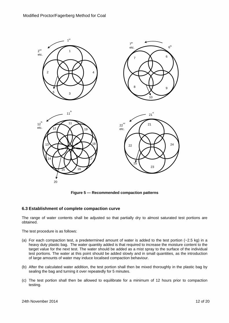
then tamp uniformly over the surface by dropping the hammer 25 times vertically through the full height of the guide pipe, moving the guide pipe to a new position after each drop. The required pattern for even compaction of each layer in the mould is shown in Figure 5.
(e) Repeat step (d) four more times so that there are 5 layers of material in the mould. Ensure that the
compacted test portion with the final layer is above the top of the compaction mould whilst the extension piece is still attached.
(f) When the last layer has been tamped, remove the extension piece taking care not to disturb the
compacted test portion inside. Level the compacted test portion to the top of the mould using the flat scraping device, ensuring that any large particles that may hinder levelling of the test portion are removed and replaced with material contained in the extension piece and re-level. If any holes in the surface are still observed after levelling, they should be manually filled with finer material contained in the extension piece. Care shall be taken to avoid any further compaction of the test portion.
(g) Determine the mass (B) of the mould and compacted coal and then calculate the mass, C, of the wet test
portion using the equation:
C = B – A (1)
(h) When the weight of the cylinder with the tamped test portion has been determined, remove the test portion from the mould, determine the mass of the wet test portion, C1, and dry the entire test portion in an oven at 105°C until constant mass is achieved. After drying, determine the weight, D1, of the dried test portion and then calculate the percentage gross water content, W1 , as follows: W1 = (C1 – D1)/C1 x 100 %
(i) Using the calculated gross water content, calculate the mass of the dry test portion in the mould after
drying, D, using the equation:
D = C – C x W1/100 (2)
(j) Calculate the mass, E, of water in the mould using the equation:
E = C – D (3)
(k) Discard the used coal sample. Coal from a previously compacted test portion shall not be re-used.
Modified Proctor/Fagerberg Method for Coal
24th November 2014 12 of 20
Figure 5 — Recommended compaction patterns
6.3 Establishment of complete compaction curve
The range of water contents shall be adjusted so that partially dry to almost saturated test portions are obtained.
The test procedure is as follows:
(a) For each compaction test, a predetermined amount of water is added to the test portion (~2.5 kg) in a heavy duty plastic bag. The water quantity added is that required to increase the moisture content to the target value for the next test. The water should be added as a mist spray to the surface of the individual test portions. The water at this point should be added slowly and in small quantities, as the introduction of large amounts of water may induce localised compaction behaviour.
(b) After the calculated water addition, the test portion shall then be mixed thoroughly in the plastic bag by sealing the bag and turning it over repeatedly for 5 minutes.
(c) The test portion shall then be allowed to equilibrate for a minimum of 12 hours prior to compaction testing.
2
1 2nd etc.
1st
3
4
5
6
7th etc. 6th
12
11 12th
etc.
11th
15
14
13 18
17
16
19
20
7
8 9
10
22
21 22nd
etc.
21st
23
24
25
Modified P
24th Novem
(d) Repeat
(e) Repeat contentthat at lof 70%degree saturati
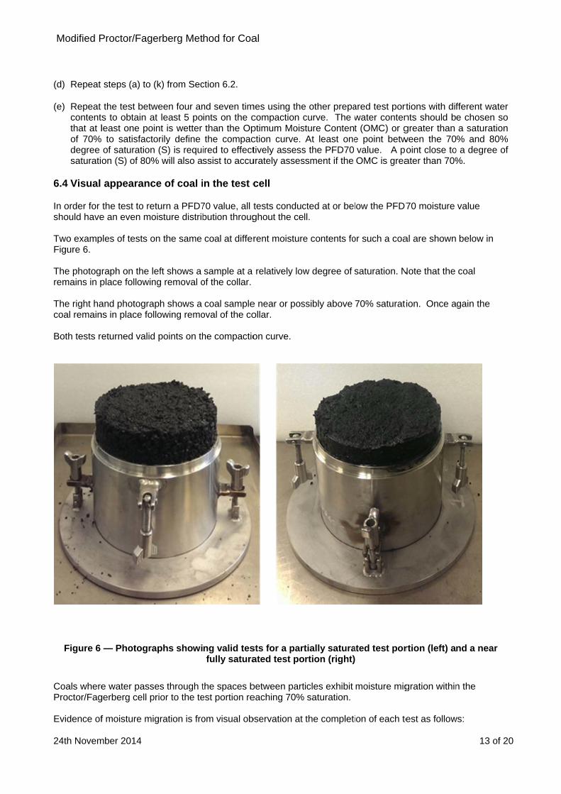
6.4 Visual
In order for should have Two exampFigure 6. The photogremains in p The right hacoal remain Both tests r
Figure 6
Coals whereProctor/Fag Evidence of
Proctor/Fag
mber 2014
steps (a) to
the test betwts to obtain aleast one po to satisfactof saturationon (S) of 80%
appearanc
the test to ree an even mo
ples of tests o
raph on the place followin
and photograns in place fo
eturned valid
— Photogra
e water passgerberg cell p
f moisture m
erberg Met
(k) from Sec
ween four anat least 5 pooint is wetter torily define n (S) is requ% will also a
ce of coal i
eturn a PFD7oisture distrib
on the same
left shows a ng removal o
aph shows a ollowing remo
d points on th
aphs showi
ses through tprior to the te
igration is fro
hod for Coa
ction 6.2.
nd seven timints on the cthan the Opthe compac
ired to effectssist to accu
n the test c
70 value, all tbution throug
coal at differ
sample at a of the collar.
coal sampleoval of the co
he compactio
ng valid tesfully satura
the spaces best portion re
om visual ob
al
mes using thecompaction cptimum Moisction curve. tively assess
urately asses
cell
tests conducghout the ce
rent moisture
relatively low
e near or posollar.
on curve.
sts for a partated test po
between parteaching 70%
bservation at
e other prepacurve. The w
sture ContentAt least one
s the PFD70 ssment if the
cted at or belll.
e contents fo
w degree of s
ssibly above
tially saturartion (right)
ticles exhibit saturation.
the completi
ared test portwater content (OMC) or ge point betwvalue. A poOMC is grea
low the PFD7
or such a coa
saturation. N
70% saturat
ated test por
moisture mig
ion of each te
rtions with difnts should bgreater than ween the 70oint close toater than 70%
70 moisture
al are shown
Note that the
tion. Once a
rtion (left) a
gration within
est as follow
13 of 2
fferent watere chosen soa saturation% and 80%
o a degree of%.
value
below in
coal
gain the
nd a near
n the
ws:
20
r o n
% f

Modified Proctor/Fagerberg Method for Coal
24th November 2014 14 of 20
Moisture leakage from the base of the mould is evident in Figure 7; and
The portion above the top of the cell appears unsaturated and the test portion maintains its structure without deformation or movement.
In this case, moisture migration has occurred and hence for this coal water passes through the spaces between particles.
Figure 7 — Test showing water leakage from the base of the cell indicating moisture migration
6.5 Calculation of key parameters for determination of compaction curve
Carry out the following calculations for each compaction test. These are summarised in Table 2. = dry bulk density, g/cm3 (t/m3)
= D/V ev = net water content (percentage by volume)
= (E/D) × 100 × d/w where d = density of solid material, g/cm3 (t/m3)
w = density of water, g/cm3 (t/m3) e = void ratio (volume of voids divided by volume of solids)
= (d/) - 1 S = degree of saturation (percentage by volume)
= ev/e
W1 = gross (total) water content (percentage by mass) – see 6.2 (g).
Moisture leaking at base
Moisture leaking at base
Non-saturated top

Modified P
24th Novem
Vari
Den
Dry
Net
Void
Deg
Gros
6.6 Presen
Record all tthis spreadseach compa
The straigh40%, 60%, using the fo
Proctor/Fag
mber 2014
iable
nsity of solid
bulk density
water conten
d ratio (volum
gree of satura
ss water con
ntation of c
the compactsheet createaction test on
t lines in Fig70%, 80% a
ormulae in Se
erberg Met
Table 3
material
y
nt (% by volu
me voids / vo
ation (% by v
ntent (% by m
compaction
tion test resu a compaction the Y-axis
gure 8 corresand 100% deection 6.5 ab
F
10
hod for Coa
3 – Key calcu
ume)
olume solids)
volume)
mass)
n results
ults in a suitaon curve as against the g
spond to ploegree of satubove.
Figure 8 – Ty
15 2
al
ulations for
Sym
d
ev
) e
S
W
able spreadsshown in Figgross water c
ots of void raration (S). T
ypical comp
20 25
TML determ
bol
From
v
W1
sheet (such gure 8 by plocontent (W1)
atio (e) versuhese lines ar
paction curv
30
mination
Calcu
m pycnomete
=
ev = E/D ×
e = d
S =
See 6
as that showotting the calplotted on th
us gross watre calculated
ve
ulation
ter (see 5.2.4
D/V
× d/w ×100
d/ -1
ev/e
6.2 (h)
wn in Table lculated voidhe X-axis.
ter content (d at 5 values
15 of 2
4(g)).
4) and fromd ratio (e) for
W1) at 20%, of void ratio
20
m r
, o

Modified P
24th Novem
6.7 Sampl
An exampleprovided in as describe
The preferre(W1) allowinapproach is
e = W1/
The intercewater conteat a degree
Figure 9 –
0.
0.
0.4
0.5
0.
Void Ratio ‐e
Proctor/Fag
mber 2014
e compact
e of the resuTable 4, witd below.
ed approachng moisture fs shown in Fi
/(100 - W1) ×
pt of the coment of 15.4%,
of saturation
– Example othe
2
3
4
5
6
6 7
Grinte
Proctor
erberg Met
tion curve
ults obtainedth the corres
h to presentinfor any saturgure 9. The
× 100 × d / S
mpaction cur, which is then of about 85
of a measuree 70%, 80%,
8 9 10
oss water conersection betwsaturation linr/Fagerberg cu
hod for Coa
when applyponding com
ng the resultration level to saturation li
rve with the e Transporta5%.
ed compact90% and 10
11 12 1
Gross
ntent for the ween the 70% e and the urve (ev = 15.4
al
ying the modmpaction cur
ts is to plot to be read diines are plott
70% degreeable Moisture
ion curve fo00% degree
13 14 15
Water Con
4%)
dified Proctorve and the 7
the void ratiorectly from thted accordin
e of saturatioe Limit (TML
or void ratioof saturatio
16 17 1
ntent ‐W1 (
r/Fagerberg 70% degree
o (e) against he plot as grg to the equa
on line in Fig). For this ex
versus groon lines plot
18 19 20
(%)
OptimuMoistuConte
test to a coof saturation
the gross wross water coation:
gure 9 occurxample, the O
oss water cotted
21 22 2
um ure ent
16 of 2
al sample isn line plotted
water contentontent. This
rs at a grossOMC occurs
ontent with
23 24
20
s d
t s
s s
Modified Proctor/Fagerberg Method for Coal
24th November 2014 17 of 20
6.8 Determination of transportable moisture limit
6.8.1 Determination of PFD70 Moisture Content
The critical moisture content is determined from the intersection of the compaction curve and the line S = 70% degree of saturation, with the gross (total) water content (W1) corresponding to this intersection defined as the PFD70 value. The PFD70 value is reported as the Transportable Moisture Limit.
The Optimum Moisture Content (OMC) is the gross (total) moisture content corresponding to the maximum compaction (maximum dry density and minimum e) under the specified compaction condition.
The test procedure is applicable for determination of coal TML where the degree of saturation corresponding to the OMC of the coal is at or greater than 70% saturation. Where the OMC lies below 70% saturation, this test may not be applicable for the specific coal and the PFD70 may overstate the TML. In such cases, the certificate of analysis shall state that the OMC is below 70% saturation and the shipper should consult with an appropriate authority,
6.8.2 Cases where the highest determinable point on the compaction curve lies below 70% saturation
In coals where there is visual evidence that water passes through the spaces between particles and the compaction curve does not extend to or beyond the 70% saturation line, the coal is deemed to be free draining and a TML value is not applicable. By reference to the IMSBC Code s7.2.2, such coals are cargoes where liquefaction does not occur.
7 Test Report
The test report shall include the following information:
(a) Identification of the sample;
(b) A unique reference to this document;
(c) Reference to the appropriate standard adopted for determining the density of the solids;
(d) Either:
i) The transportable moisture limit (TML) of the sample, expressed as the gross water content as a percentage of the sample by mass; or
ii) A statement that the test indicated that water passes through the spaces between particles at a moisture content below 70% saturation, and the coal is therefore not Group A.
(e) The solids density d in g/cm3.

Modified Proctor/Fagerberg Method for Coal
24th November 2014 18 of 20
Table 4 – Example of TML determination for a coal sample using the modified Proctor/Fagerberg method
Note: The example above uses two drying trays for each test.
Product Diameter of cylinder 150 mm Laboratory temperature 25°C Date
Sample Height of cylinder 120 mm Mass of mould (A) 7271 g Size
fraction
Initial gross water content (%) 5.6 Volume of cylinder 2121 ml Initial Dry density 899 kg/m3 Operator Density of solids 1416 kg/m3 TML 15.4% Tamper 337.5 g
Test number
Water added
Mass of mould + sample
Tray No.
Mass of tray
Mass of wet sample +
tray
Mass of dry sample +
tray
Measured gross water
content
Gross water
content
Net water content
Void ratio
Dry density
Degree of saturation
Wet bulk density
Mass of wet sample
Mass of dry
sample
Mass of water
(ml) (g) (g) (g) (g) (%) (%) (%v) (g/cm3) (%) (g/cm3) (g) (g) (g) B W1 eV e S C D E
1 0.00 9360.00 T1 602.5 1656.8 1565.7 8.64
8.67 13.437 0.573 0.899 23.4 0.985 2089.0 1907.8 181.2 T2 602.3 1643.1 1552.5 8.70
2 150.00 9692.70 T3 630.7 1811.7 1649.6 13.73
13.51 22.097 0.433 0.988 51.1 1.142 2421.7 2094.6 327.1 T4 882.9 2126.9 1961.6 13.29
3 250.00 9881.60 T5 638.7 2081.4 1849.7 16.06
15.58 26.104 0.362 1.039 72.2 1.231 2610.6 2204.0 406.6 T6 632.4 1822.6 1643.0 15.09
4 350.00 9971.00 T7 882.2 2349.9 2095.4 17.34
17.31 29.630 0.344 1.053 86.1 1.273 2700.0 2232.5 467.5 T8 637.9 1868.8 1656.0 17.29
5 450.00 9996.20 T9 654.3 2013.2 1746.5 19.63
19.73 34.780 0.372 1.031 93.5 1.285 2725.2 2187.5 537.7 T10 639.6 1999.4 1729.7 19.83
6 550.00 9980.00 T11 885.0 2251.5 1931.6 23.41
22.17 40.311 0.423 0.994 95.2 1.277 2709.0 2108.4 600.6 T12 883.5 2181.9 1910.1 20.93
7
8
9
10

Modified Proctor/Fagerberg Method for Coal
24th November 2014 19 of 20
Annex A Example of a Proctor/Fagerberg Apparatus
Drop
Height
150mm
Compaction Cylinder Compaction Hammer
Mould
Base Recess
Removal extension
piece
Hammer 337.5g
Base
Hammer
Diameter 75mm
Air relief hole
Figure A.1 – Schematic of a Proctor/Fagerberg apparatus
Hei
ght o
f dro
p
Drop Height 150mm

Modified Proctor/Fagerberg Method for Coal
24th November 2014 20 of 20
Table 5 – Specifications and tolerances for Proctor/Fagerberg cell and hammer
Parameter Units Dimension Tolerance
Hammer mass g 337.5 ± 2
Hammer diameter mm 75 ± 0.2
Drop height mm 150 ± 2
Tube ID mm 78 ± 0.2
Tube OD mm 82 ± 0.2
Tube wall thickness mm 2 ± 0.2
Tube clearance mm 1.5 ± 0.2
Mould inner diameter mm 150 ± 0.5
Mould inner height mm 120 ± 1
Mould inner volume cm3 2121 ± 18
Removable extension piece height mm 75 ± 1
Depth of recess into base to seat mm 1 ± 0.2
Gap between mould and base mm ≤ 0.1
Gap between mould and extension piece mm Easy running fit
(AS 1100) (0 to +0.1)
Clearance between mould and hammer mm ≤ 6


