35
ELECTRICAL POWER T&D SYSTEM MODULE VI – ELECTRIC POWER DISTRIBUTION SYSTEM FOR INDUSTRIAL PLANTS
| Date post: | 17-Jan-2016 |
| Category: |
Documents |
| Upload: | yusup-suryadi |
| View: | 39 times |
| Download: | 0 times |
ELECTRICAL POWER T&D SYSTEM
M O D U L E V I – E L E C T R I C P O W E R D I S T R I B U T I O N S Y S T E M F O R I N D U S T R I A L P L A N T S
OVERVIEW
IEEE Std 141-1993,
IEEE Recommended Practice for Electrical Power Distribution for Industrial Plants
OVERVIEW
The term industrial plants, as used in this chapter, refers to industrial plants, buildings, and complexes where manufacturing, industrial production, research, and development are performed.
It does not include commercial buildings, such as institutional, governmental, public, health-related office buildings, nor apartment and residential buildings.
VOLTAGE CONSIDERATIONS
An understanding of system voltage nomenclature and the preferred voltage ratings of distribution apparatus and utilization equipment is essential to ensure proper voltage identification throughout a power distribution system
Term and definition refer to ANSI C84.1-1989 to identify the voltages and voltage classes used in electric power distribution
Nominal system voltage is near the voltage level at which the system normally operates. To allow for operating contingencies, systems generally operate at voltage levels about 5-10% below the maximum system voltage for which system components are designed.
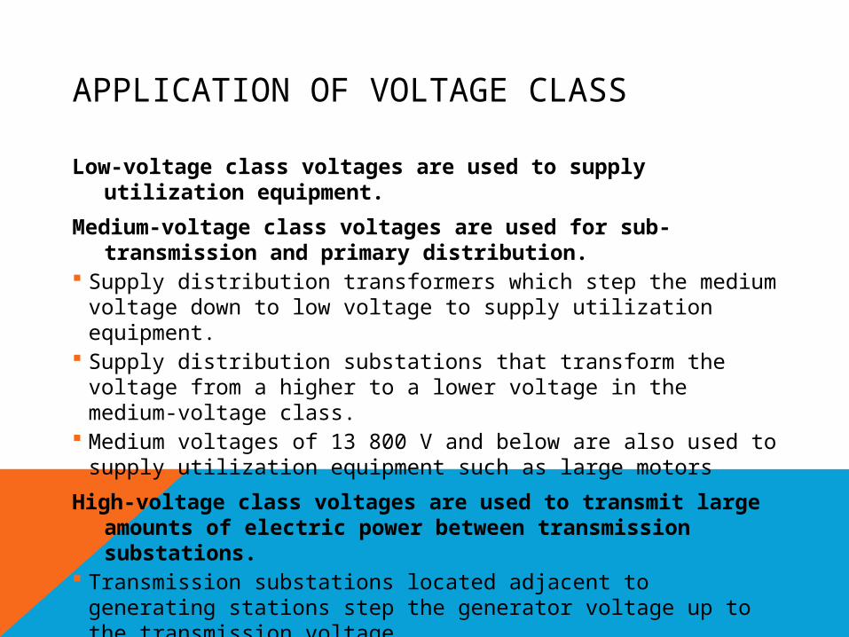
APPLICATION OF VOLTAGE CLASS
Low-voltage class voltages are used to supply utilization equipment.
Medium-voltage class voltages are used for sub-transmission and primary distribution.
Supply distribution transformers which step the medium voltage down to low voltage to supply utilization equipment.
Supply distribution substations that transform the voltage from a higher to a lower voltage in the medium-voltage class.
Medium voltages of 13 800 V and below are also used to supply utilization equipment such as large motors
High-voltage class voltages are used to transmit large amounts of electric power between transmission substations.
Transmission substations located adjacent to generating stations step the generator voltage up to the transmission voltage.
Other transmission substations transform the high voltage down to medium voltage for sub-transmission and primary distribution.

ANSI C84.1-1989 Standard Nominal System Voltages & Voltage Ranges
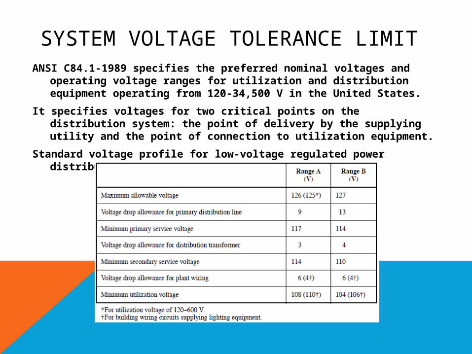
SYSTEM VOLTAGE TOLERANCE LIMITANSI C84.1-1989 specifies the preferred nominal voltages and
operating voltage ranges for utilization and distribution equipment operating from 120-34,500 V in the United States.
It specifies voltages for two critical points on the distribution system: the point of delivery by the supplying utility and the point of connection to utilization equipment.
Standard voltage profile for low-voltage regulated power distribution system, 120 V base:
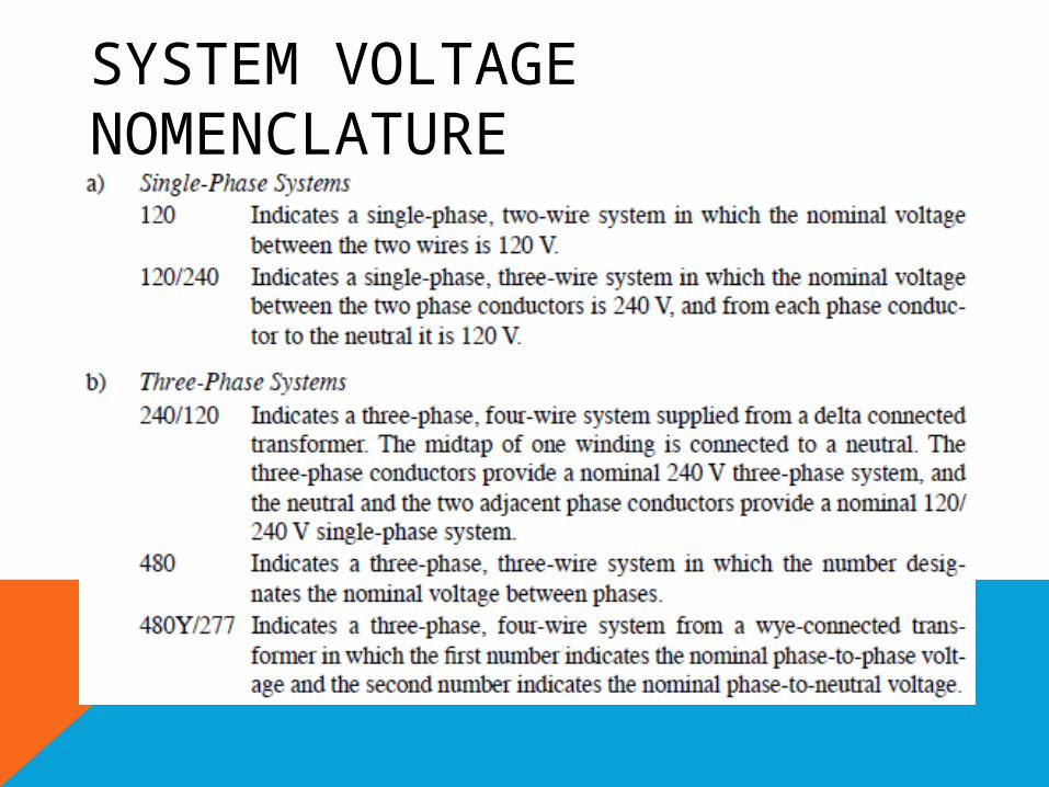
SYSTEM VOLTAGE NOMENCLATURE
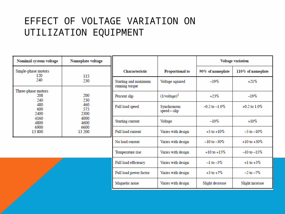
EFFECT OF VOLTAGE VARIATION ON UTILIZATION EQUIPMENT
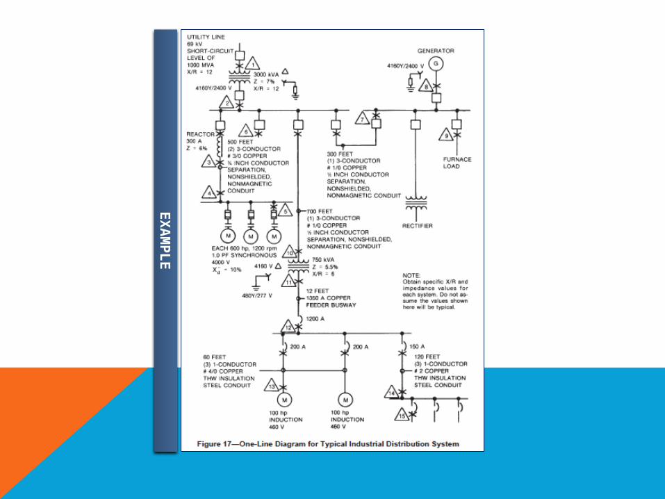
EX
AM
PLE
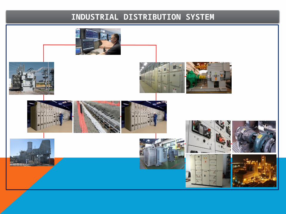
INDUSTRIAL DISTRIBUTION SYSTEM

POWER QUALITY
Voltage Drop
Voltage unbalance
Voltage sag & flicker
Harmonics
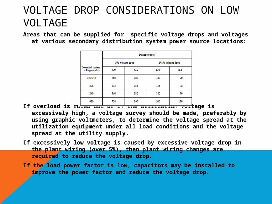
VOLTAGE DROP CONSIDERATIONS ON LOW VOLTAGEAreas that can be supplied for specific voltage drops and voltages
at various secondary distribution system power source locations:
If overload is ruled out or if the utilization voltage is excessively high, a voltage survey should be made, preferably by using graphic voltmeters, to determine the voltage spread at the utilization equipment under all load conditions and the voltage spread at the utility supply.
If excessively low voltage is caused by excessive voltage drop in the plant wiring (over 5%), then plant wiring changes are required to reduce the voltage drop.
If the load power factor is low, capacitors may be installed to improve the power factor and reduce the voltage drop.
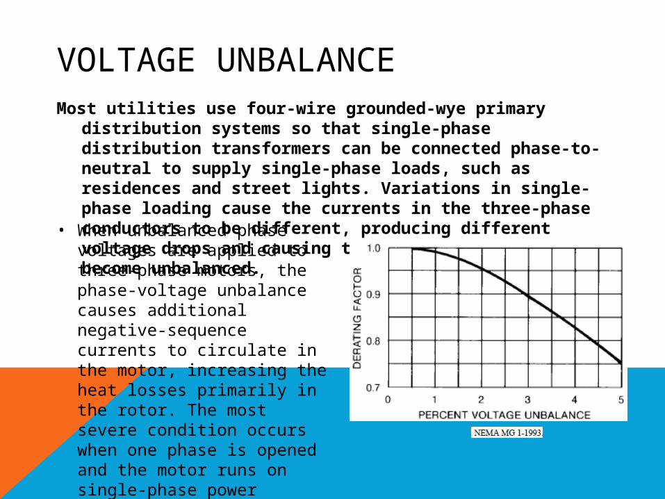
VOLTAGE UNBALANCEMost utilities use four-wire grounded-wye primary
distribution systems so that single-phase distribution transformers can be connected phase-to-neutral to supply single-phase loads, such as residences and street lights. Variations in single-phase loading cause the currents in the three-phase conductors to be different, producing different voltage drops and causing the phase voltages to become unbalanced.
• When unbalanced phase voltages are applied to three-phase motors, the phase-voltage unbalance causes additional negative-sequence currents to circulate in the motor, increasing the heat losses primarily in the rotor. The most severe condition occurs when one phase is opened and the motor runs on single-phase power
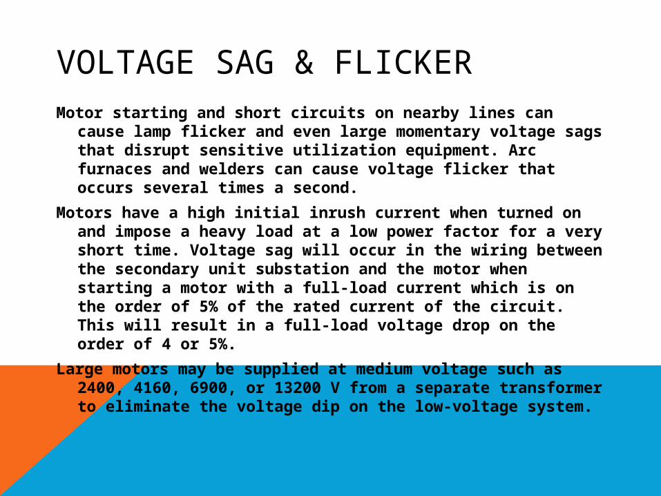
VOLTAGE SAG & FLICKERMotor starting and short circuits on nearby lines can cause
lamp flicker and even large momentary voltage sags that disrupt sensitive utilization equipment. Arc furnaces and welders can cause voltage flicker that occurs several times a second.
Motors have a high initial inrush current when turned on and impose a heavy load at a low power factor for a very short time. Voltage sag will occur in the wiring between the secondary unit substation and the motor when starting a motor with a full-load current which is on the order of 5% of the rated current of the circuit. This will result in a full-load voltage drop on the order of 4 or 5%.
Large motors may be supplied at medium voltage such as 2400, 4160, 6900, or 13200 V from a separate transformer to eliminate the voltage dip on the low-voltage system.
VOLTAGE SAG & FLICKER
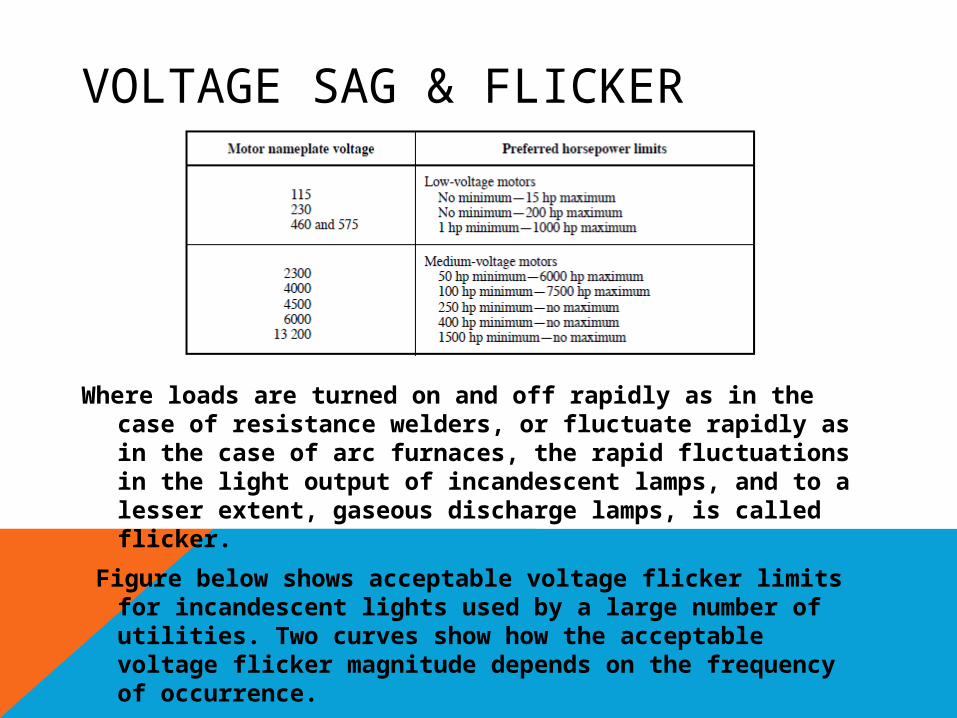
Where loads are turned on and off rapidly as in the case of resistance welders, or fluctuate rapidly as in the case of arc furnaces, the rapid fluctuations in the light output of incandescent lamps, and to a lesser extent, gaseous discharge lamps, is called flicker.
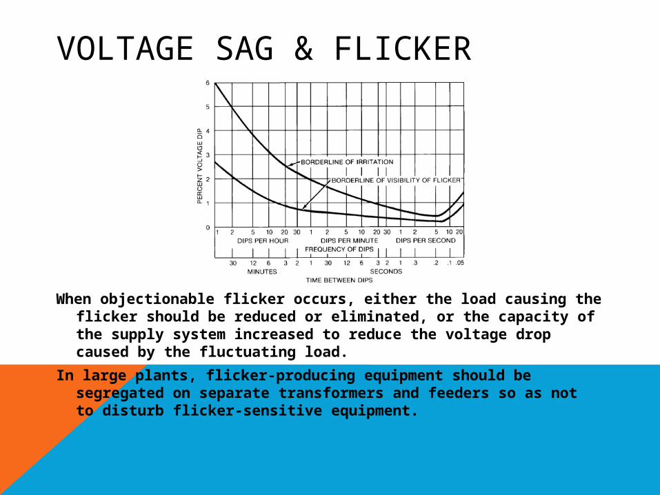
Figure below shows acceptable voltage flicker limits for incandescent lights used by a large number of utilities. Two curves show how the acceptable voltage flicker magnitude depends on the frequency of occurrence.
VOLTAGE SAG & FLICKER
When objectionable flicker occurs, either the load causing the flicker should be reduced or eliminated, or the capacity of the supply system increased to reduce the voltage drop caused by the fluctuating load.
In large plants, flicker-producing equipment should be segregated on separate transformers and feeders so as not to disturb flicker-sensitive equipment.
VOLTAGE SAG & FLICKER
Solid-state controllers such as adjustable speed drives, microprocessor controllers, sensors, and other equipment are often sensitive to momentary voltage sags associated with remote electrical short circuits.
The duration of voltage sags depends upon the time required to detect and interrupt the short circuit current. Typical minimum interruption time for medium- and high-voltage circuit breakers are 3-5 cycles at 60 Hz while older breakers may be rated for 8 cycles.
Some sags last even longer because of required time delay for overcurrent coordination.
Probability density of voltage sag duration had a duration less than 0.2 s
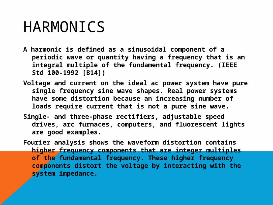
HARMONICSA harmonic is defined as a sinusoidal component of a
periodic wave or quantity having a frequency that is an integral multiple of the fundamental frequency. (IEEE Std 100-1992 [B14])
Voltage and current on the ideal ac power system have pure single frequency sine wave shapes. Real power systems have some distortion because an increasing number of loads require current that is not a pure sine wave.
Single- and three-phase rectifiers, adjustable speed drives, arc furnaces, computers, and fluorescent lights are good examples.
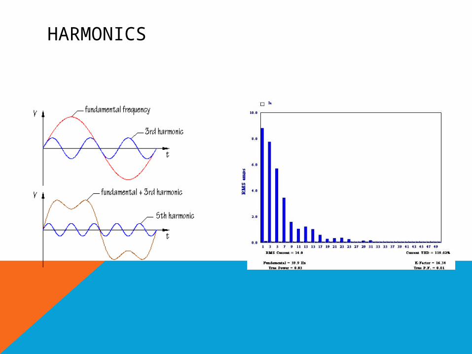
Fourier analysis shows the waveform distortion contains higher frequency components that are integer multiples of the fundamental frequency. These higher frequency components distort the voltage by interacting with the system impedance.
HARMONICS
EFFECT OF HARMONICS
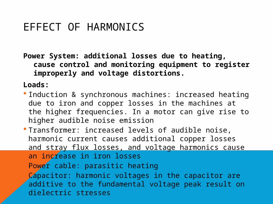
Power System: additional losses due to heating, cause control and monitoring equipment to register improperly and voltage distortions.
Loads: Induction & synchronous machines: increased heating due to
iron and copper losses in the machines at the higher frequencies. In a motor can give rise to higher audible noise emission
Transformer: increased levels of audible noise, harmonic current causes additional copper losses and stray flux losses, and voltage harmonics cause an increase in iron losses
Power cable: parasitic heating Capacitor: harmonic voltages in the capacitor are additive to
the fundamental voltage peak result on dielectric stresses
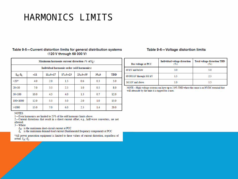
HARMONICS LIMITS
MITIGATION OF HARMONICS
Shunt filters: The most common method used to control the fow of harmonic currents. They are designed as a series combination of reactors (inductance) and capacitors (capacitance). To act as “trap” because it absorbs the harmonic current to which it is tuned.
Phase-shifting transformers: delta-delta transformer connections with delta-wye connections will eliminate some of the fifth and seventh harmonic currents when there are several drives operating in a facility
Harmonic current injection: injecting equivalent currents that are phase-shifted 180o. This technique, which is called active filtering

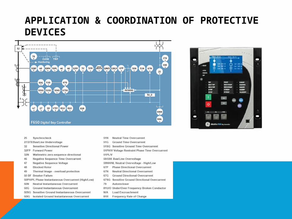
APPLICATION & COORDINATION OF PROTECTIVE DEVICES
Power system protective devices provide the intelligence and initiate the action that enables circuit switching equipment to respond to abnormal or dangerous system conditions.
Normally, relays control power circuit breakers rated above 600V and current-responsive self-contained elements operate multiple-pole low-voltage circuit breakers to isolate circuits experiencing overcurrents on any phase.
In systems employing circuit breakers, other than those with direct acting devices that use fault current to power relaying and trip functions, there is always a risk that during a fault the system voltage can drop suddenly to a value too low for the protective devices to function. For this reason station battery sets, or capacitor trip devices, are usually employed to provide tripping energy.
APPLICATION & COORDINATION OF PROTECTIVE DEVICES
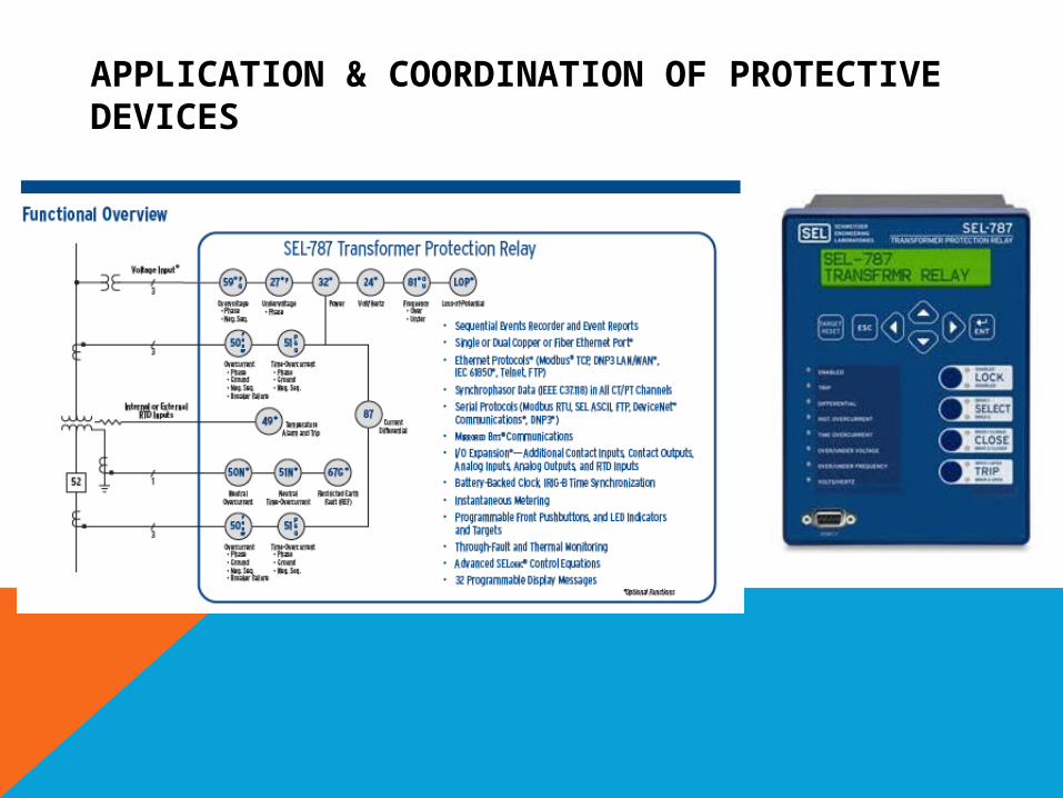
APPLICATION & COORDINATION OF PROTECTIVE DEVICES
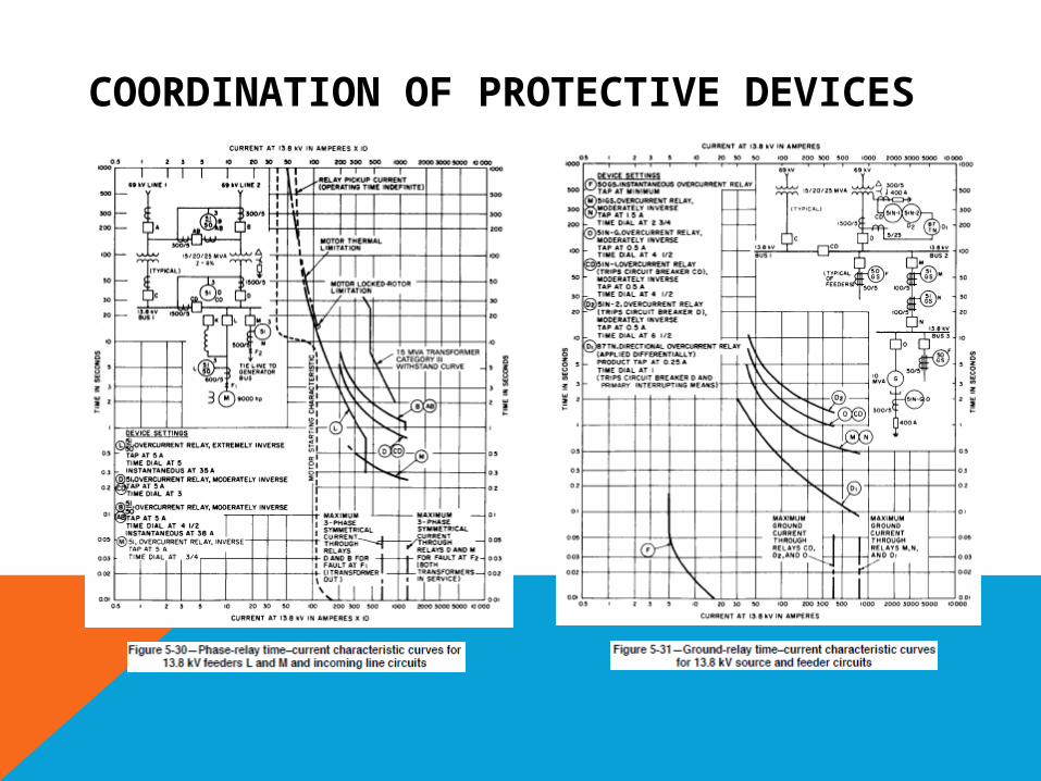
COORDINATION OF PROTECTIVE DEVICES
Determining the settings and ratings for the overcurrent devices in a power system is an important task and, when correctly done, assures the intended performance of the system.
Continuity of plant electric service requires that interrupting equipment operate in a selective manner. This may require longer opening times (for a given current) of the interrupters successively closer to the power source during faults. The necessity for maximum safety to personnel and electric equipment, on the other hand, calls for the fastest possible isolation of faulted circuits.
The coordination curve plot provides a graphical means of displaying the competing objectives of selectivity and protection.
A total time margin of 0.40 s at maximum fault current is sufficient to afford satisfactory selectivity between inverse-time relays (electromechanical relays) . Further reduction of this margin (to approximately 0.20-0.25 s) is possible with solid-state relays which reset rapidly.
COORDINATION OF PROTECTIVE DEVICES

SWITCHGEARSwitchgear is a general term that describes switching and
interrupting devices, either alone or in combination with other associated control, metering, protective, and regulating equipment, which are assembled in one or more sections.
A power switchgear assembly consists of a complete assembly of one or more of the above noted devices and main bus conductors, interconnecting wiring, accessories, supporting structures, and enclosure. Power switchgear is applied throughout the electric power system of an industrial plant, but is principally used for incoming line service and to control and protect load centers, motors, transformers, motor control centers, panel boards, and other secondary distribution equipment.
An open switchgear assembly is one that does not have an enclosure as part of the supporting structure.
An enclosed switchgear assembly consists of a metal-enclosed supporting structure with the switchgear enclosed on the top and all sides with sheet metal
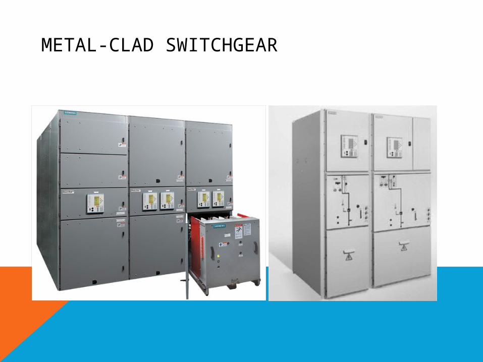
METAL-CLAD SWITCHGEARThe main circuit switching and interrupting device is of the removable type arranged
with a mechanism for moving it physically between connected and disconnected positions, and equipped with self-aligning and self-coupling primary and secondary disconnecting devices.
Major parts of the primary circuit, such as the circuit switching or interrupting devices, buses, potential transformers, and control power transformers, are enclosed by grounded metal barriers. Specifically included is an inner barrier in front of, or as a part of, the circuit interrupting device to ensure that no energized primary circuit components are exposed when the unit door is opened.
All live parts are enclosed within grounded metal compartments. Automatic shutters prevent exposure of primary circuit elements when the removable element is in the test, disconnected, or fully withdrawn position.
Primary bus conductors and connections are covered with insulating material throughout. For special configurations, insulated barriers between phases and between phase and ground may be specified.
Mechanical interlocks are provided to ensure a proper and safe operating sequence.
Instruments, meters, relays, secondary control devices, and their wiring are isolated by grounded metal barriers from all primary circuit elements, with the exception of short lengths of wire associated with instrument transformer terminals.
The door, through which the circuit-interrupting device is inserted into the housing, may serve as an instrument or relay panel and may also provide access to a secondary or control compartment within the housing.
METAL-CLAD SWITCHGEAR
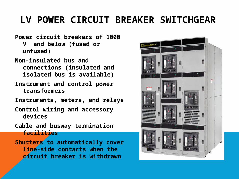
LV POWER CIRCUIT BREAKER SWITCHGEAR
Power circuit breakers of 1000 V and below (fused or unfused)
Non-insulated bus and connections (insulated and isolated bus is available)
Instrument and control power transformers
Instruments, meters, and relays
Control wiring and accessory devices
Cable and busway termination facilities
Shutters to automatically cover line-side contacts when the circuit breaker is withdrawn
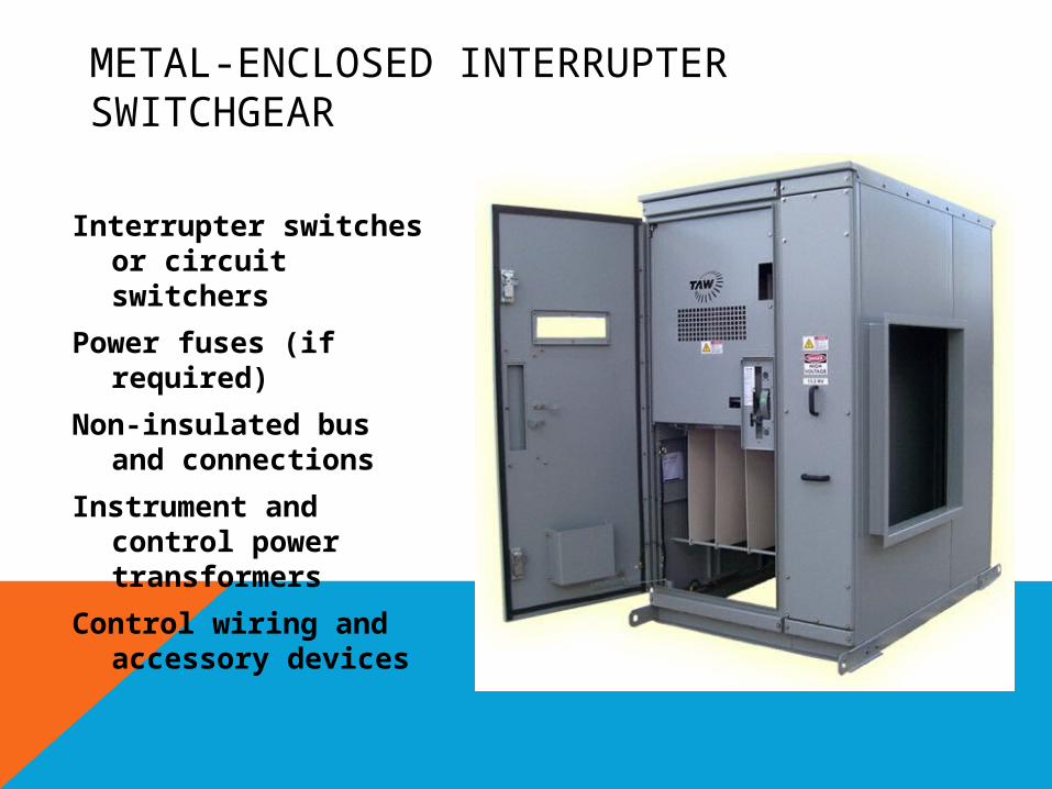
METAL-ENCLOSED INTERRUPTER SWITCHGEAR
Interrupter switches or circuit switchers
Power fuses (if required)
Non-insulated bus and connections
Instrument and control power transformers
Control wiring and accessory devices
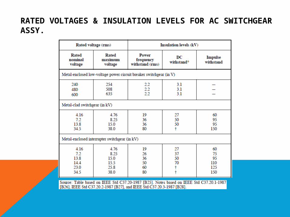
RATED VOLTAGES & INSULATION LEVELS FOR AC SWITCHGEAR ASSY.

END


