45
Modul 7 Konsep Dasar Multiple Antena Modul 7 Multiple Antenna Faculty of Electrical Engineering Bandung – 2015 Wireless Communication System

Modul 7 Konsep Dasar Multiple Antena
Modul 7 Multiple Antenna
Faculty of Electrical Engineering
Bandung – 2015
Wireless Communication System
Subject
a. Macam-macam Multiple Antenna (Diversitas dan
MIMO)
b. Model Sistem SISO, SIMO, MISO, MIMO
Modul 7 Multiple Antenna
01

Text Book
Modul 7 Multiple Antenna
02
Modul 7 Multiple Antenna
03

Modul 7 Multiple Antenna
04

Rina P. Astuti6
Multiple Antenna vs Fading05

Modul 7 Multiple Antenna
06

Diversity & MIMO
Modul 7 Multiple Antenna
07

Modul 7 Multiple Antenna
0808

Modul 7 Multiple Antenna
09

Modul 7 Multiple Antenna
10
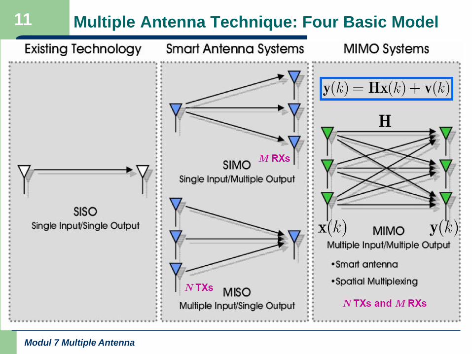
Multiple Antenna Technique: Four Basic Model
Modul 7 Multiple Antenna
11

Modul 7 Multiple Antenna
12

SISO
Modul 7 Multiple Antenna
Radio transmissions traditionally use one antenna at
the transmitter and one antenna at the receiver.
This system is termed Single Input Single Output
(SISO).
Picture. Single Input Single Output
(SISO)
One antenna at both the transmitter
and the receiver.
Employs no diversity technique.
Both the transmitter and the receiver
have one RF chain (that's coder and
modulator). SISO is relatively simple
and cheap to implement and it has
been used age long since the birth of
radio technology.
It is used in radio and TV broadcast
and our personal wireless
technologies (e.g. Wi-Fi and
Bluetooth).
13

SIMO
Modul 7 Multiple Antenna
To improve performance, a multiple antenna technique has been developed.
A system which uses a single antenna at the transmitter and multiple
antennas at the receiver is named Single Input Multiple Output (SIMO). The
receiver can either choose the best antenna to receive a stronger signal or
combine signals from all antennas in such a way that maximizes SNR
(Signal to Noise Ratio). The first technique is known as switched diversity or
selection diversity. The latter is known as maximal ratio combining (MRC).
Picture. Single Input Multiple Output (SIMO), 1x2
One antenna at the transmitter, two antennas the receiver.
Employs a receive diversity technique.
14

MISO
Modul 7 Multiple Antenna
A system which uses multiple antennas at the transmitter and a
single antenna at the receiver is named Multiple Input Single
Output (MISO). A technique known as Alamouti STC (Space
Time Coding) is employed at the transmitter with two antennas.
STC allows the transmitter to transmit signals (information)
both in time and space, meaning the information is transmitted
by two antennas at two different times consecutively.
Picture. Multiple Input Single Output (MISO), 2x1
Two antennas at the transmitter, one antenna at the receiver.
Employs a transmit diversity technique.
14

MIMO
Modul 7 Multiple Antenna
To multiply throughput of a radio link, multiple antennas (and multiple
RF chains accordingly) are put at both the transmitter and the receiver.
This system is referred to as Multiple Input Multiple Output (MIMO).
A MIMO system with similar count of antennas at both the transmitter
and the receiver in a point-to-point (PTP) link is able to multiply the
system throughput linearly with every additional antenna. For
example, a 2x2 MIMO will double the throughput.
Picture. Multiple Input Multiple Output (MIMO), 2x2
Two antennas at both the transmitter and the receiver.
16
Modul 7 Multiple Antenna
17

Rina P. Astuti
18
19
Objective : to support private and public access
– high data rate transmission
– high mobility
– High signal performance
New transmission
techniques
Selective fading
Costly to estimate
the channel accurately
Performance degradation
Multi users
ProblemsMultiple antennas & multi-carrier techniques
Non coherent transmission scheme
Coding techniques
Multiple access
OFDM, Coded OFDM, OFCDM, MC-CDMA
Differential modulation
outer & inner codingFDMA, TDMA, CDMA
Examples :

Modern Wireless Transceiver
Modul 7 Multiple Antenna
19
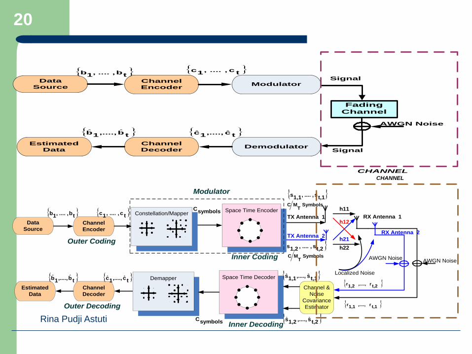
21
Data
Source
Estimated
Data
Channel
Decoder
Channel
Encoder
SymbolsT
MC
t,1s,....,1,1s
t,2s,....,1,2s
h11
h12
h22
h21 TX Antenna 2
AWGN NoiseAWGN Noise
t,2r,....,1,2r
t,1r,....,1,1r
RX Antenna 1
RX Antenna 2
Localized Noise
symbolsC tc,....,1c tb,....,1b
Outer Coding
Inner Coding SymbolsT
MC
TX Antenna 1Constellation/Mapper
Demapper
Space Time Encoder
Space Time Decoder
Channel &
Noise
Covariance
Estimator
tb,....,1b ˆˆ tc,....,1c ˆˆ t,1s,....,1,1s ˆˆ
t,2s,....,1,2s ˆˆsymbolsC
Outer Decoding
Inner Decoding
Modulator
CHANNEL
Data
Source
Estimated
Data
Channel
Decoder
Channel
Encoder
Demodulator
Modulator
Fading
Channel
AWGN Noise
tb,....,1b tc,....,1c
Signal
tb,....,1b ˆˆ tc,....,1c ˆˆ
Signal
CHANNEL
Rina Pudji Astuti
20

Innovation of Wireless Systems
Modul 7 Multiple Antenna
21

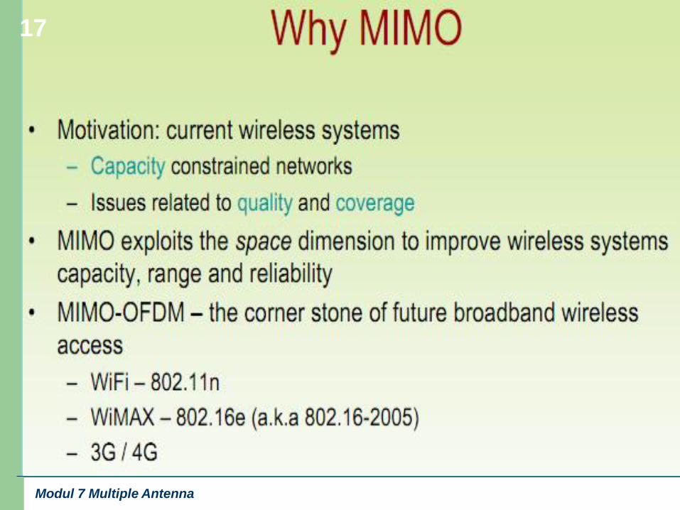
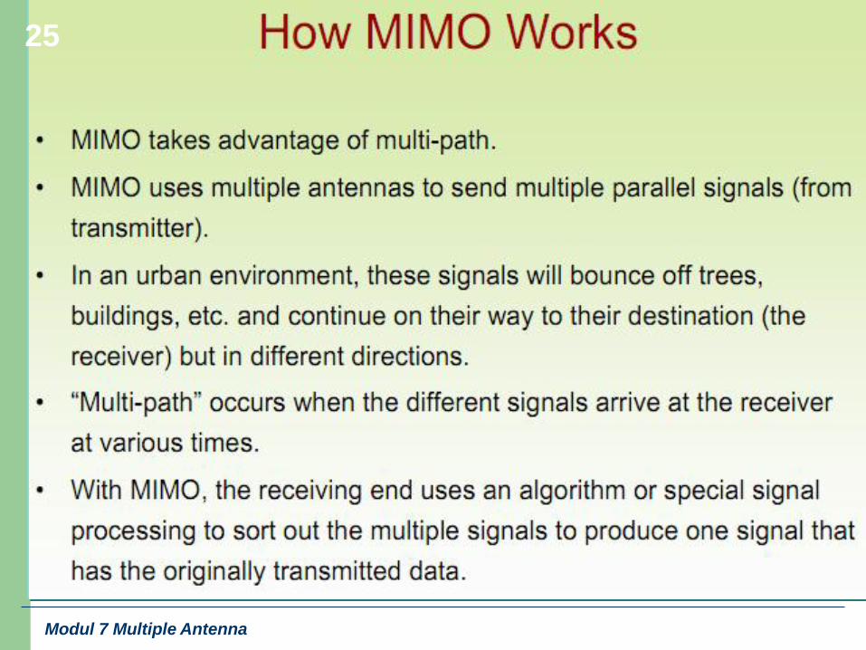
What is MIMO ?
Modul 7 Multiple Antenna
22

Required Knowledge
Modul 7 Multiple Antenna
23

Modul 7 Multiple Antenna
24
Modul 7 Multiple Antenna
25

Modul 7 Multiple Antenna
26

MIMO Operation
Modul 7 Multiple Antenna
27

Modul 7 Multiple Antenna
28

Macam-2 Teknik Space Time
Teknik Space Time
(MIMO)
Memaksimalkan
Diversitas
Memaksimalkan
Laju Data
Space Time
Block Codes
Space Time
Trellis Codes
Layered ST
architecture
Threaded ST
architecture
Other Inner
code
performance-rate complexity tradeoffs
Rina Pudji Astuti
29

Multiple Antenna Technique
Two popular techniques in MIMO wireless systems:
Spatial Diversity: Increased SNR
• Receive and transmit diversity mitigates
fading and improves link quality
Spatial Multiplexing: Increased rate
• Spatial multiplexing yields substantial
increase spectral efficiency
Modul 7 Multiple Antenna
30

Spatial Diversity and Spatial Multiplexing
Spatial Diversity
– Signal copies are transferred from multiple antennas or
received at more than one antenna
– redundancy is provided by employing an array of
antennas, with a minimum separation of λ/2 between
neighbouring antennas
Spatial Multiplexing
– the system is able to carry more than one data stream
over one frequency, simultaneously
31

33
Spatial MultiplexingMaximize Data Rate (rate oriented)
• MIMO dengan Skema Vertical Encoding
• MIMO dengan Skema Horizontal Encoding
4:1
Demux
Code / mod
Code / mod
Code / mod
Code / mod
1
2
3
4
t1S
t3S
t4S
t2S
Primitive data
Stream
AntennasSpace
4LAYER
1LAYER
2LAYER
3LAYER
4-D vector symbols duration
( Antenna )
Time
1
2
4
3
Temporal Code +
Interleaving +
Symbol Mapper Demultiplex
TM:1
SymbolsT
MC
SymbolsT
MC
TMTMC
symbolsCbitsq
32

Rina Pudji Astuti34
• MIMO dengan Skema Diagonal Encoding
4:1
Demux
Code / mod layer A
Code / mod layer B
Code / mod layer C
Code / mod layer D
1
2
3
4
Primitive data
Stream
AntennasSpace
4LAYER
1LAYER
2LAYER
3LAYER
4-D vector symbols duration
( Antenna )
Layer A
Layer A
Layer A
Layer A
Layer A
Layer D
Layer D
Layer D
Layer D
Layer C
Layer C
Layer C
Layer B
Layer B
Layer A
Layer A
Layer A
Layer A
Layer ALayer D
Layer D
Layer B
Layer C
Layer C
Layer C
Layer B
Layer B
Layer B
Time
1
2
4
3
Spatial Multiplexing33
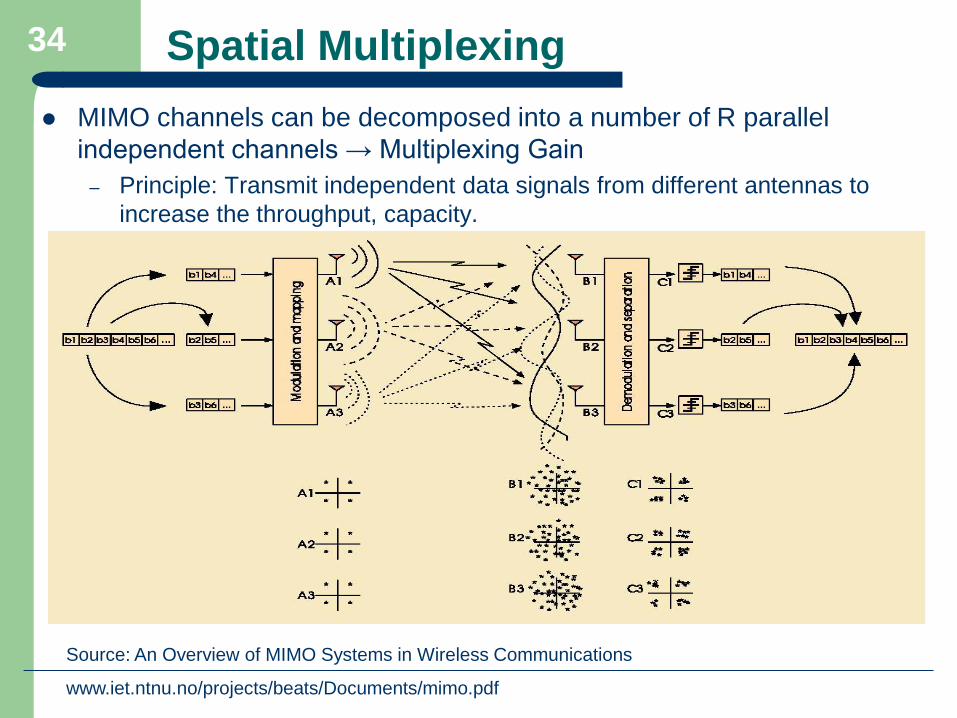
Spatial Multiplexing
MIMO channels can be decomposed into a number of R parallel
independent channels → Multiplexing Gain
– Principle: Transmit independent data signals from different antennas to
increase the throughput, capacity.
Source: An Overview of MIMO Systems in Wireless Communications
www.iet.ntnu.no/projects/beats/Documents/mimo.pdf
34

Spatial Multiplexing
Modul 7 Multiple Antenna
Spatial multiplexing bertujuan untuk meningkatkan kapasitas dengan
cara mengirimkan beberapa aliran data secara paralel pada waktu yang
bersamaan.
Prinsip kerja dari spatial multiplexing adalah mengirim sinyal dari
dua atau lebih antenna yang berbeda dengan beberapa aliran data dan
aliran data dipisahkan dipenerima dengan proses signal processing,
oleh karena itu peningkatan bit rate berdasarkan konfigurasi antenna
mimo ( 2 untuk antenna mimo 2 by 2 and 4 untuk antena mimo 4 by 4)
35

Spatial Multiplexing
MIMO Multiplexing
Data is not redundant – less diversity but less repetition
Provides multiplexing gain to increase data-rate
Low (no) diversity compared with STC
Modul 7 Multiple Antenna
36

38
Maximize Diversity Transmission Scheme
(performance oriented) in MIMO Wireless Systems
Transceiver
System
Coherent Ch. Scheme
Non Coherent Ch
Scheme
Traditional Inner
Coding
Differential Modulation
Differential Inner
Coding
Transmission
Scheme
Channel State
Information
with channel
estimation
scheme
With or Non
Channel State
Information
with
differential
modulation
e.g. Space time
block code, STTC
Unitary code, etc
e.g. D-STBC,
D-Unitary code,
DUSTF code,
MC-CDMA Multilevel
Coding etc
OFDM
Coded OFDM
MC CDMA
Multicarrier
Techniques
Rina Pudji Astuti
37

Spatial Diversity
Improves the signal quality and achieves a higher SNR at the receiver-
side
Principle of diversity relies on the transmission of structured
redundancy
xiyi
38

Spatial Diversity
Modul 7 Multiple Antenna
Beberapa replika sinyal informasi dikirim dari beberapa antenna
yang berbeda (data informasi yang dikirim yaitu data info asli dan
replika). Tujuan spatial diversity yaitu untuk meningkatkan SNR
dengan cara mengurangi fading dan meningkatkan kualitas link antara
pengirim dengan penerima.
39

Modul 7 Multiple Antenna
40

Rina P. Astuti42
• Space Time Block Code (STBC) [Alamouti1998]
– At the Receivers, after demodulator :
dual diversity
Combiner
Estimate
Antena
Pemancar
(Jamak)
*
2C,1C
*
1C,2C
*
2C,1C h
h 2C,1C
~~
2h,1h~~
ncHy . 21 yyy
Tcc ][ 21c
12
21
hh
hhH
2
1
12
21
21 ]~~[y
y
hh
hhcc
'2
'1
2212
2
2
2
122111
2
2
2
1
nn
nhnhchhnhnhchh
2
2
2
1 hhg
Space Time Coding
virtual MIMO matrix
41

Rina P. Astuti
43
Space Time Coding
• Space Time Block Code (STBC) [Tarokh1999]
• Alamouti Model, 2 Tx antennas and 2 Rx
• At the Receivers, after demodulator :
• Quadruple diversity
4
3
34
43
2
1
12
21
21
~~
y
y
hh
hh
y
y
hh
hhcc
1
443322111
2
4
2
3
2
2
2
1
n
nhnhnhnhchhhh
2
443312212
2
4
2
3
2
2
2
1
n
nhnhnhnhchhhh
'.~ ng cc
2
4
2
3
2
2
2
1 hhhhg
42

• Space Time Trellis Code (STTC) [Tarokh1998]
– 2 – space time code, 4 PSK, 4 – state, 2 b/s/Hz
Deretan bit masukan
Derajat memory: dan , dengan , sehingga jumlah state
Pasangan koefisien pengkode:
dimana.
KeluaranSTTC: dengan
0
2
1
3
10 11 12 13
20 21 22 23
30 31 32 33
00 01 02 03 Input : 02321103
Tx1 : 00232110
Tx2 : 0232110302
1
3
Space Time Coding
,,,,1111
kkk dddd ,,,,2222
kkk dddd
,
.
1v2v 21 vvv 42 v
1
2,
1
1,
1
2,1
1
1,1
1
2,0
1
1,0
1
11,,,,, vv gggggg g
2
2,
2
1,
2
2,1
2
1,1
2
2,0
2
1,0
2
11,,,,, vv gggggg g 3,2,1,0,
j
lig
4mod)(2
1 0
,
j
v
i
j
ik
j
lil
j
dgks 2,1l
Rina P. Astuti
43

Space Time Coding
Aliran bit masukan, d : merupakan masukan sebuah modulasi M-PSK yang difungsikan sebagai pemeta simbol(mapper), dimana
Pengkode STTC yang terdiri dari m feedforward shift register akan memetakan deretan bit masukan menjadi himpunan sinyal M-PSK.
Deretan bit masukan ke k, dimasukkan ke shift register ke k dan dikalikan dengan sebuah himpunan koefisien pengkode, berupa himpunan konstelasi M-PSK. Keluaran pengkode pada saat k, berupa sinyal-sinyal termodulasi membentuk simbol berbasis ruang-waktu (space time symbol), dapat dinyatakan sebagai berikut:
,,,, 10 kdddd
Tm
kkkk ddd ,,,21 d
TMk ksksks
T)(,),(),( 11 s
Mdgksm
j
v
i
j
ik
j
lil
j
mod)(1 0
,
TM
j
lig ,
kv
kv
adalah jumlah antena pemancar
adalah elemen himpunan konstelasi M-PSK
adalah derajat memori shift register ke kRina P. Astuti
44


