55
MODULAR CLASSROOM PROJECT STATEMENT OF REQUIREMENTS (ISSUED FOR CONTRACT - OCTOBER 4, 2010)

MODULARCLASSROOM PROJECTSTATEMENT OF REQUIREMENTS
(ISSUED FOR CONTRACT - OCTOBER 4, 2010)

MODULAR CLASSROOMS | DESIGN STANDARDS AND PERFORMANCE SPECIFICATIONS
BLANK FOR PAGINATION

TABLE OF CONTENTS 0.0 INTRODUCTION AND INTENTIONS ....................................1
1.0 BUILDING SIZE AND FUNCTION ........................................5
2.0 INTERIOR COMPONENTS ..................................................7
3.0 EXTERIOR COMPONENTS ................................................13
4.0 MODULAR CLUSTERS .......................................................17
5.0 STRUCTURAL REQUIREMENTS ...........................................19
6.0 ELECTRICAL REQUIREMENTS .............................................23
7.0 MECHANICAL REQUIREMENTS .........................................27
8.0 APPENDIX A ROLLING SHUTTERS AND SCREENS .................33
9.0 APPENDIX B DOORS AND HARDWARE ..............................37
10.0 APPENDIX C MILLWORK QUALITY STANDARDS ....................39
11.0 APPENDIX D DEMONSTRATION STRUCTURAL DRAWINGS ....41
12.0 APPENDIX E TEACHER’S WORK CABINET DETAILS ...............48

MODULAR CLASSROOMS | DESIGN STANDARDS AND PERFORMANCE SPECIFICATIONS
BLANK FOR PAGINATION

1
0.0 INTRODUCTION AND INTENTIONS
INTRODUCTIONThe Speech from the Throne on August 25, 2009 announced that British Columbia would begin implementing full-day kindergarten (FDK) program in September 2010. This implementation will be in two stages, with the school year 2010/11 being year one and year two the 2011/12 school year. In support of this initiative, the Ministry of Education was directed to develop a plan to deliver the required classrooms by September 2011, as effi ciently and cost-effectively as possible.
OBJECTIVESThe following were established to guide the FDK program:
• Provide additional classroom capacity required for successful implementation of FDK program for the start of school in September 2011
• Ensure adaptability and fl exibility to meet changing future requirements and the potential addition of Pre-K programs
• Provide a facility solution(s) that is fl exible to meet classroom needs for students ranging from kindergarten to grade 7
• Ensure new facilities are high quality and consistent with Ministry program requirements across the province
• Provide a positive environment for students that is supportive of the Ministry’s educational goals
• Encourage a positive work environment for staff
Modular classrooms were selected as the solution that best meets the objectives, in most cases.
2 MODULAR CLASSROOMS | DESIGN STANDARDS AND PERFORMANCE SPECIFICATIONS
INTENT OF THE MODULAR CLASSROOM DESIGNThe intent is to provide facilities that are high quality, cost effective and timely. Modular classrooms are to be long-life, energy effi cient and capable of being moved. They will provide a classroom that will be substantially equal to a permanently constructed classroom with an expected 40-year life. They will be capable of assembly, disassembly, clustering and redeployment over the course of their expected life.
INTENDED EXTERIOR APPEARANCE AND IMAGEThe appearance and image of the exterior should resemble an architecture that would be considered a permanent building built with a manufactured methodology.
Elementary schools are meant to impart the sense of a welcoming and secure environment where children can feel at ease and open to play and learn by themselves and with the other children in the class. Thus the building’s exterior needs to convey colour, a welcoming sense of scale, material texture and transparency.
INTENDED INTERIOR APPEARANCE AND IMAGEThe classroom interior is the heart of learning and supports creative exploration. The interior needs to be colourful, be capable of fl exible use and allow for pin-ups and wall use for virtually its entire area. There should be plenty of daylight, soft and effective natural lighting, use of textures and colors that become an experiential part of the room.
PERFORMANCE REQUIREMENTSThe modular performance requirements will bracket certain important dimensions, materials, and confi gurations. They are not prescriptive, but set as an expectation for the size, durability, and function of the rooms both singly and in combination. We are turning to the industry’s inventiveness and knowledge to assist in solving this design problem. This document will provide information on the performance requirements of the modular classroom.
However, there are certain items that will be prescriptive. This is due to the various school districts experience in dealing with many materials and components that have proven their durability over many years.
The expectation is that these modular units will perform technically and in durability the way a purpose built school would. We are looking to develop durable buildings, with assembly, systems and materials as durable as any institutional building, but built in a factory and not stick built on site.
Throughout the document there will be references to a “Base Requirement”. This means that the proponent is to provide components or features as a base product that is an integral part of a complete product. Where a “Base Requirement” is identifi ed, there will also be a reference to “Option For Selection By School District”. This refers to an option other than the “Base Requirement” that is to be offered to the School Districts for a particular item or feature. The School Site Information Sheets that will be included in the RFP indicate the selection of the options and should be used to determine the overall quantity of each item required.

3
DESIGNING A MANUFACTURED SCHOOL BUILDINGThe following pages will describe performance requirements and illustrate key confi gurations and assemblies for a modular classroom unit that is factory built. Where specifi c components are fi xed, as to type or manufacture, a specifi cation will be provided. All modular buildings will meet all applicable Building Codes including The British Columbia Building Code, 2006 Edition, and the current Vancouver Building Bylaw.
BRITISH COLUMBIA’S “WOOD FIRST” INITIATIVEThis document refers to a number of wood related installations in construction, millwork, and fi nishing. The intent is to build with wood, and to showcase wood as an attractive and versatile product. Where wood is used, including pine beetle wood, the proponent must ensure the resulting structure or fi nishes remain extremely durable. The Wood First Act requires that if there are options available for the choice of building materials, wood must be used providing it meets BC Building Code requirements
SUSTAINABILITYThe modular unit is to be designed to meet recent sustainable construction standards by specifying a high-performance envelope, energy-effi cient mechanical and electrical systems, and low VOC material selections.

4 MODULAR CLASSROOMS | DESIGN STANDARDS AND PERFORMANCE SPECIFICATIONS
BLANK FOR PAGINATION
5
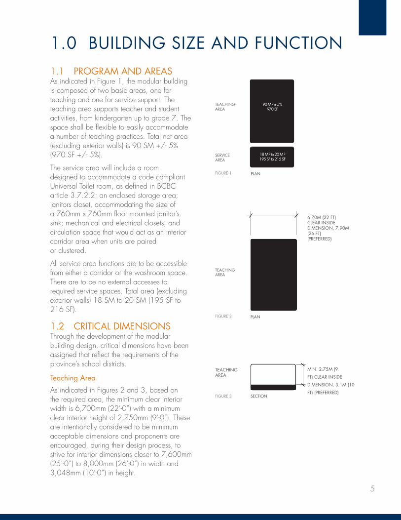
1.0 BUILDING SIZE AND FUNCTION1.1 PROGRAM AND AREASAs indicated in Figure 1, the modular building is composed of two basic areas, one for teaching and one for service support. The teaching area supports teacher and student activities, from kindergarten up to grade 7. The space shall be fl exible to easily accommodate a number of teaching practices. Total net area (excluding exterior walls) is 90 SM +/- 5% (970 SF +/- 5%).
The service area will include a room designed to accommodate a code compliant Universal Toilet room, as defi ned in BCBC article 3.7.2.2; an enclosed storage area; janitors closet, accommodating the size of a 760mm x 760mm fl oor mounted janitor’s sink; mechanical and electrical closets; and circulation space that would act as an interior corridor area when units are paired or clustered.
All service area functions are to be accessible from either a corridor or the washroom space. There are to be no external accesses to required service spaces. Total area (excluding exterior walls) 18 SM to 20 SM (195 SF to 216 SF).
1.2 CRITICAL DIMENSIONSThrough the development of the modular building design, critical dimensions have been assigned that refl ect the requirements of the province’s school districts.
Teaching Area
As indicated in Figures 2 and 3, based on the required area, the minimum clear interior width is 6,700mm (22’-0”) with a minimum clear interior height of 2,750mm (9’-0”). These are intentionally considered to be minimum acceptable dimensions and proponents are encouraged, during their design process, to strive for interior dimensions closer to 7,600mm (25’-0”) to 8,000mm (26’-0”) in width and 3,048mm (10’-0”) in height.
TEACHING AREA
SERVICE AREA
90 M ² ± 5%970 SF
18 M ² to 20 M ²195 SF to 215 SF
FIGURE 1 PLAN
6.70M (22 FT) CLEAR INSIDE DIMENSION, 7.90M (26 FT)(PREFERRED)
TEACHING AREA
FIGURE 2 PLAN
TEACHING AREA
MIN. 2.75M (9
FT) CLEAR INSIDE
DIMENSION, 3.1M (10
FT) (PREFERRED)FIGURE 3 SECTION
6 MODULAR CLASSROOMS | DESIGN STANDARDS AND PERFORMANCE SPECIFICATIONS
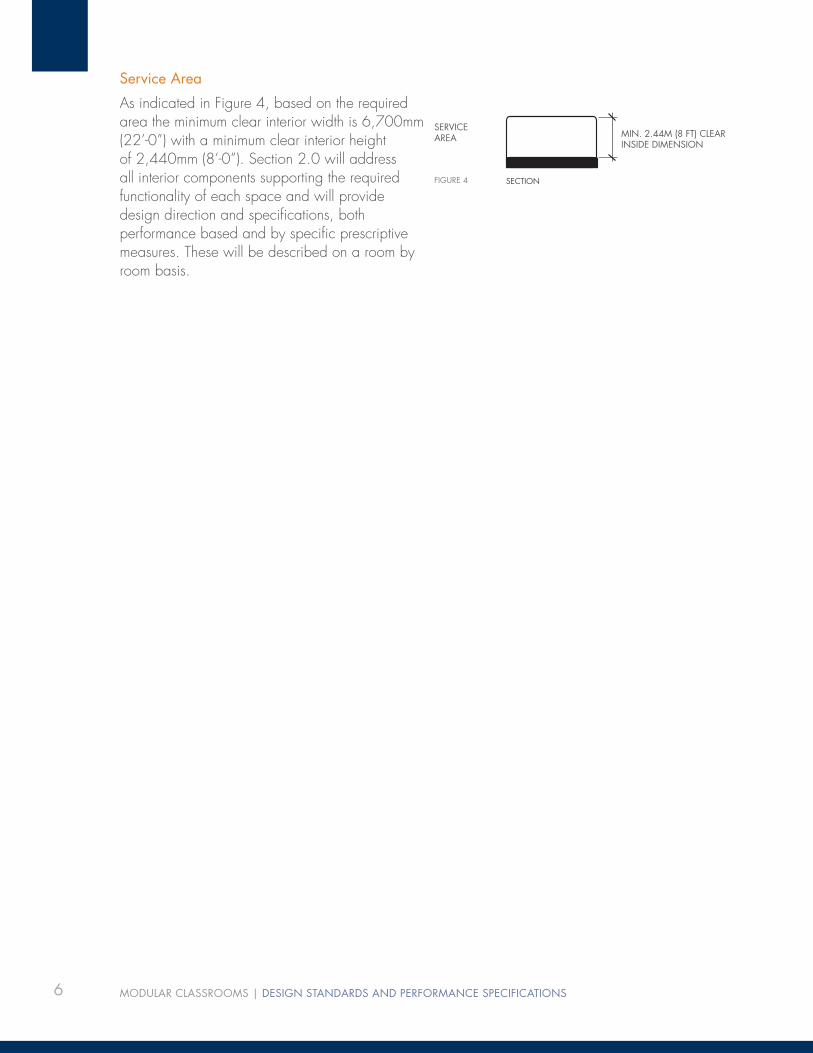
Service Area
As indicated in Figure 4, based on the required area the minimum clear interior width is 6,700mm (22’-0”) with a minimum clear interior height of 2,440mm (8’-0”). Section 2.0 will address all interior components supporting the required functionality of each space and will provide design direction and specifi cations, both performance based and by specifi c prescriptive measures. These will be described on a room by room basis.
SERVICEAREA MIN. 2.44M (8 FT) CLEAR
INSIDE DIMENSION
FIGURE 4 SECTION

7
2.0 INTERIOR COMPONENTS2.1 INTERIOR “OPAQUE” WALLS2.1.1 Teaching Area
The material selections are designed to promote durability, ease of maintenance, and support the teaching environment. As indicated in Figure 5, approximately half the area of the ‘opaque’ wall surfaces will feature wood, and the other half will have durable washable vinyl wrapped gypsum wall board panels. The exposed wood will be hardwood(s) and should be assembled in panels refl ecting the modular construction of the building.
2.1.2 Service Area
The accessible washroom area will have white FRP panels from fl oor to ceiling. The washroom area’s interior walls will be insulated with a minimum 50mm (2”) batt insulation for sound absorption. 12mm (1/2”) plywood backing installed behind the fi nish panels will allow for the hanging of sinks, grab bars, and washroom accessories. All walls of the storage area will be fi nished in 16mm (5/8”) water resistant GWB complete with 12mm (1/2”) plywood backing to a minimum of 1,828mm (6’-0”) above the fi nished fl oor. The janitors closet will have white FRP panels to 1,220mm (4’-0”) mm above the fi nished fl oor with painted 16mm (5/8”) water resistant GWB above to the underside of the ceiling. Electrical and mechanical closets will be painted 12mm (1/2”) plywood.
2.2 INTERIOR GLAZING2.2.2 Teaching Area
The design intention is to benefi t from the introduction of natural daylight reducing the requirement for artifi cial lighting, thus reducing energy consumption. As indicated in Figure 6, approximately half of the glazing should provide for high level indirect/refl ected daylighting with the other half dedicated to glazing providing views into and from the teaching area. Provide operable windows with operators placed no higher than 1,675mm (5’-6”) above the fi nished fl oor and locate operable windows to promote cross ventilation across the long axis of the space. Operable windows will be ‘hopper in’ type units with cam lever locks and governors. Refer to the Section 3.1.2 Exterior Glazing for additional performance requirements.
FIGURE 6
TEACHING AREA
A - HIGH LEVEL
GLAZING
B - REFLECTED LIGHT
C - LOW LEVEL VISION
GLAZING
A
B
CMIN. 2440MM (8 FT) AFF
8 MODULAR CLASSROOMS | DESIGN STANDARDS AND PERFORMANCE SPECIFICATIONS
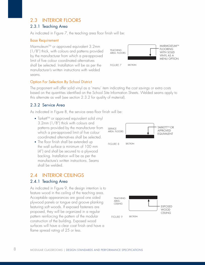
2.3 INTERIOR FLOORS2.3.1 Teaching Area
As indicated in Figure 7, the teaching area fl oor fi nish will be:
Base Requirement
MarmoleumTM or approved equivalent 3.2mm (1/8”) thick, with colours and patterns provided by the manufacturer from which a pre-approved limit of fi ve colour coordinated alternatives shall be selected. Installation will be as per the manufacturer’s written instructions with welded seams.
Option For Selection By School District
The proponent will offer solid vinyl as a ‘menu’ item indicating the cost savings or extra costs based on the quantities identifi ed on the School Site Information Sheets. Welded seams apply to this alternate as well (see section 2.3.2 for quality of material).
2.3.2 Service Area
As indicated in Figure 8, the service area fl oor fi nish will be:
• TarkettTM or approved equivalent solid vinyl 3.2mm (1/8”) thick with colours and patterns provided by the manufacturer from which a pre-approved limit of fi ve colour coordinated alternatives shall be selected.
• The fl oor fi nish shall be extended up the wall surface a minimum of 100 mm (4”) and shall be secured to a plywood backing. Installation will be as per the manufacture’s written instructions. Seams shall be welded.
2.4 INTERIOR CEILINGS2.4.1 Teaching Area
As indicated in Figure 9, the design intention is to feature wood in the ceiling of the teaching area. Acceptable appearances are good one sided plywood panels or tongue and groove planking featuring soft woods. If exposed fasteners are proposed, they will be organized in a regular pattern reinforcing the pattern of the modular construction of the building. Exposed wood surfaces will have a clear coat fi nish and have a fl ame spread rating of 25 or less.
FIGURE 7
MARMOLEUMTM FLOORING WITH SOLID VINYL AS A MENU OPTION
TEACHING AREA: FLOORS
SECTION
FIGURE 8
SERVICEAREA: FLOORS
SECTION
TARKETTTM OR APPROVED EQUIVALENT
FIGURE 9
TEACHING AREA: CEILING
EXPOSED WOOD CEILING
SECTION

9
2.4.2 Service Areas
As indicated in Figure 10, ceilings in the service areas are to be either suspended T-bar or suspended 16mm (5/8”) painted gypsum wall board both provided with a washable surface fi nish. If the proponent opts for a gypsum wall board ceiling that is painted, access panels to mechanical and electrical systems are to be provided.
2.5 MILLWORK2.5.1 Teaching Area
The individual millwork, as described below, is to be located to support the requirements of teaching methods and will have the following relationships to the teaching area. The teacher’s cabinet, coat hooks, and student cubbies will be located adjacent to the entrance. The millwork (with sinks and taps provided by the school districts) will face on to the teaching area and be serviced from the adjacent service area. All millwork is to be manufactured and installed to AWMAC standards (see appendix).
2.5.1.1 Teacher’s Cabinet
Teacher’s cabinet (refer to Figure 11) will be 915mm (3’-0”) wide, 2,032mm (6’-8”) tall and 24” deep complete with lockable doors, 4” shelves for paper storage, and four fi le drawers at the bottom in a side-by-side confi guration.
Construction: 16mm (5/8”) plywood with two coats of clear urethane fi nish hardwoods, concealed hinges, cam locks, and door pulls. (Refer to the drawing in the Appendix for the standard unit confi guration).
2.5.1.2 Coat Hooks
Coat hooks (refer to Figure 12) are provided for 30 students with two height hooks—one for back packs and one for coats (total of 60).
Construction: Stainless steel fi nish mounted on plywood back board with fi nish to match teacher’s cabinet. Provide 2 separate but paired hooks per child,one for clothing and the other for a backpack—one above the other. Hooks shall not present a hazard of injury to children by virtue of their shape or placement.
2.5.1.3 Cubbies
Cubbies (refer to Figure 13) 254mm W x 305mm D x 152mm H (10”W x 12”D x 6”H) are provided for 30 students.
Construction: 16mm (5/8”) plywood complete with 6mm edge banding to match the veneer. All shall be fi nished with two coats of clear urethane.
FIGURE 10
SERVICEAREA: CEILING
SECTION
T-BAR OR SUSPENDED GWB
FIGURE 11
FIGURE 12 - NOTE: THIS EXAMPLE SHOWS ACRYLIC HOOKS. STAINLESS STEEL IS REQUIRED.
10 MODULAR CLASSROOMS | DESIGN STANDARDS AND PERFORMANCE SPECIFICATIONS
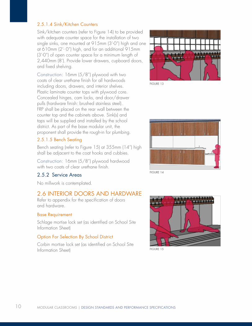
2.5.1.4 Sink/Kitchen Counters
Sink/kitchen counters (refer to Figure 14) to be provided with adequate counter space for the installation of two single sinks, one mounted at 915mm (3’-0”) high and one at 610mm (2’- 0”) high, and for an additional 915mm (3’-0”) of open counter space for a minimum length of 2,440mm (8’). Provide lower drawers, cupboard doors, and fi xed shelving.
Construction: 16mm (5/8”) plywood with two coats of clear urethane fi nish for all hardwoods including doors, drawers, and interior shelves. Plastic laminate counter tops with plywood core. Concealed hinges, cam locks, and door/drawer pulls (hardware fi nish: brushed stainless steel). FRP shall be placed on the rear wall between the counter top and the cabinets above. Sink(s) and taps will be supplied and installed by the school district. As part of the base modular unit, the proponent shall provide the rough-in for plumbing.
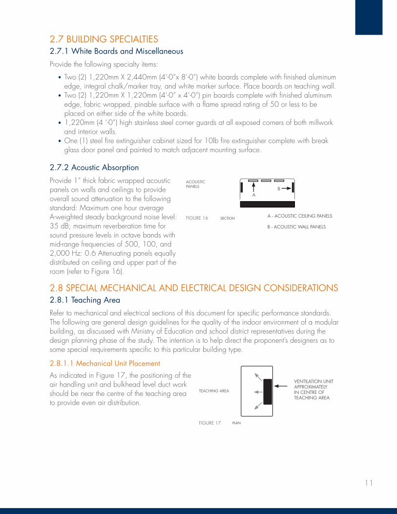
2.5.1.5 Bench Seating
Bench seating (refer to Figure 15) at 355mm (14”) high shall be adjacent to the coat hooks and cubbies.
Construction: 16mm (5/8”) plywood hardwood with two coats of clear urethane fi nish.
2.5.2 Service Areas
No millwork is contemplated.
2.6 INTERIOR DOORS AND HARDWARERefer to appendix for the specifi cation of doors and hardware.
Base Requirement
Schlage mortise lock set (as identifi ed on School Site Information Sheet)
Option For Selection By School District
Corbin mortise lock set (as identifi ed on School Site Information Sheet)
FIGURE 13
FIGURE 14
FIGURE 15
11
2.7 BUILDING SPECIALTIES2.7.1 White Boards and Miscellaneous
Provide the following specialty items:
• Two (2) 1,220mm X 2,440mm (4’-0”x 8’-0”) white boards complete with fi nished aluminum edge, integral chalk/marker tray, and white marker surface. Place boards on teaching wall.
• Two (2) 1,220mm X 1,220mm (4’-0” x 4’-0”) pin boards complete with fi nished aluminum edge, fabric wrapped, pinable surface with a fl ame spread rating of 50 or less to be placed on either side of the white boards.
• 1,220mm (4 ‘-0”) high stainless steel corner guards at all exposed corners of both millwork and interior walls.
• One (1) steel fi re extinguisher cabinet sized for 10lb fi re extinguisher complete with break glass door panel and painted to match adjacent mounting surface.
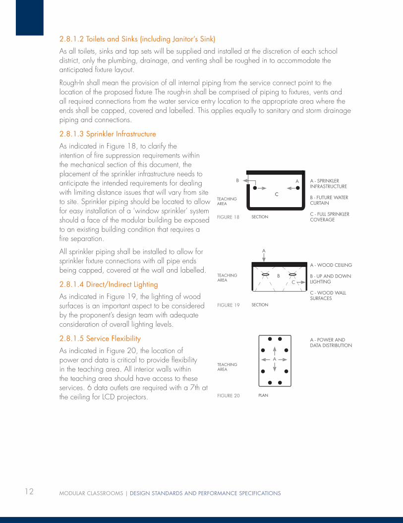
2.7.2 Acoustic Absorption
Provide 1” thick fabric wrapped acoustic panels on walls and ceilings to provide overall sound attenuation to the following standard: Maximum one hour average A-weighted steady background noise level: 35 dB; maximum reverberation time for sound pressure levels in octave bands with mid-range frequencies of 500, 100, and 2,000 Hz: 0.6 Attenuating panels equally distributed on ceiling and upper part of the room (refer to Figure 16).
2.8 SPECIAL MECHANICAL AND ELECTRICAL DESIGN CONSIDERATIONS2.8.1 Teaching Area
Refer to mechanical and electrical sections of this document for specifi c performance standards. The following are general design guidelines for the quality of the indoor environment of a modular building, as discussed with Ministry of Education and school district representatives during the design planning phase of the study. The intention is to help direct the proponent’s designers as to some special requirements specifi c to this particular building type.
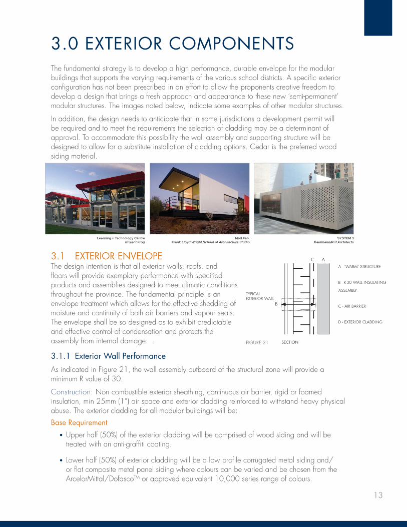
2.8.1.1 Mechanical Unit Placement
As indicated in Figure 17, the positioning of the air handling unit and bulkhead level duct work should be near the centre of the teaching area to provide even air distribution.
FIGURE 16 A - ACOUSTIC CEILING PANELS
B - ACOUSTIC WALL PANELS
ACOUSTIC PANELS
SECTION
A B
FIGURE 17
TEACHING AREA
VENTILATION UNIT APPROXIMATELY IN CENTRE OF TEACHING AREA
PLAN
12 MODULAR CLASSROOMS | DESIGN STANDARDS AND PERFORMANCE SPECIFICATIONS
2.8.1.2 Toilets and Sinks (including Janitor’s Sink)
As all toilets, sinks and tap sets will be supplied and installed at the discretion of each school district, only the plumbing, drainage, and venting shall be roughed in to accommodate the anticipated fi xture layout.
Rough-In shall mean the provision of all internal piping from the service connect point to the location of the proposed fi xture The rough-in shall be comprised of piping to fi xtures, vents and all required connections from the water service entry location to the appropriate area where the ends shall be capped, covered and labelled. This applies equally to sanitary and storm drainage piping and connections.
2.8.1.3 Sprinkler Infrastructure
As indicated in Figure 18, to clarify the intention of fi re suppression requirements within the mechanical section of this document, the placement of the sprinkler infrastructure needs to anticipate the intended requirements for dealing with limiting distance issues that will vary from site to site. Sprinkler piping should be located to allow for easy installation of a ‘window sprinkler’ system should a face of the modular building be exposed to an existing building condition that requires a fi re separation.
All sprinkler piping shall be installed to allow for sprinkler fi xture connections with all pipe ends being capped, covered at the wall and labelled.
2.8.1.4 Direct/Indirect Lighting
As indicated in Figure 19, the lighting of wood surfaces is an important aspect to be considered by the proponent’s design team with adequate consideration of overall lighting levels.
2.8.1.5 Service Flexibility
As indicated in Figure 20, the location of power and data is critical to provide fl exibility in the teaching area. All interior walls within the teaching area should have access to these services. 6 data outlets are required with a 7th at the ceiling for LCD projectors.
FIGURE 18 SECTION
A - SPRINKLER INFRASTRUCTURE
B - FUTURE WATER CURTAIN
C - FULL SPRINKLER COVERAGE
TEACHING AREA
FIGURE 19
TEACHING AREA
SECTION
A - WOOD CEILING
B - UP AND DOWN LIGHTING
C - WOOD WALL SURFACES
A
BC
FIGURE 20 PLAN
TEACHING AREA
A - POWER AND DATA DISTRIBUTION
A
AB
C
13
3.0 EXTERIOR COMPONENTSThe fundamental strategy is to develop a high performance, durable envelope for the modular buildings that supports the varying requirements of the various school districts. A specifi c exterior confi guration has not been prescribed in an effort to allow the proponents creative freedom to develop a design that brings a fresh approach and appearance to these new ‘semi-permanent’ modular structures. The images noted below, indicate some examples of other modular structures.
In addition, the design needs to anticipate that in some jurisdictions a development permit will be required and to meet the requirements the selection of cladding may be a determinant of approval. To accommodate this possibility the wall assembly and supporting structure will be designed to allow for a substitute installation of cladding options. Cedar is the preferred wood siding material.
3.1 EXTERIOR ENVELOPEThe design intention is that all exterior walls, roofs, and fl oors will provide exemplary performance with specifi ed products and assemblies designed to meet climatic conditions throughout the province. The fundamental principle is an envelope treatment which allows for the effective shedding of moisture and continuity of both air barriers and vapour seals. The envelope shall be so designed as to exhibit predictable and effective control of condensation and protects the assembly from internal damage. .
3.1.1 Exterior Wall Performance
As indicated in Figure 21, the wall assembly outboard of the structural zone will provide a minimum R value of 30.
Construction: Non combustible exterior sheathing, continuous air barrier, rigid or foamed insulation, min 25mm (1”) air space and exterior cladding reinforced to withstand heavy physical abuse. The exterior cladding for all modular buildings will be:
Base Requirement
• Upper half (50%) of the exterior cladding will be comprised of wood siding and will be treated with an anti-graffi ti coating.
• Lower half (50%) of exterior cladding will be a low profi le corrugated metal siding and/or fl at composite metal panel siding where colours can be varied and be chosen from the ArcelorMittal/DofascoTM or approved equivalent 10,000 series range of colours.
Mod.Fab.Frank Lloyd Wright School of Architecture Studio
Learning + Technology Centre Project Frog
SYSTEM 3Kaufmann/Rüf Architects
FIGURE 21
TYPICAL EXTERIOR WALL
SECTION
A - ‘WARM’ STRUCTURE
B - R-30 WALL INSULATING
ASSEMBLY
C - AIR BARRIER
D - EXTERIOR CLADDING
A
B
C

14 MODULAR CLASSROOMS | DESIGN STANDARDS AND PERFORMANCE SPECIFICATIONS
Option For Selection By School District
• Option 1: All wood, the exterior cladding will be comprised of wood siding and will be treated with
an anti-graffi ti coating.• Option 2:
Upper half (50%) of the exterior cladding will be comprised of wood siding and will be treated with an anti-graffi ti coating.
Lower half (50%) will consist of panelized masonry consisting of brick preassembled into panels that are applied to the structure as a rain screen.
• Option 3: Upper half (50%) of the exterior cladding will be comprised of wood siding and will be
treated with an anti-graffi ti coating. Lower half (50%) will consist of Hardie Plank or approved equivalent consisting of non
asbestos fi ber cement planks with adequate mechanical back-up to ensure impact resistance durably fastened to the structure as a rain screen.
Fire Retardant
In locations where local codes require a fi re retarding Class A fl ame spread rating for wood cladding, the wood will be treated with a clear fi re retardant coating that can be painted, or otherwise fi nished by a school district. Locations to be determined by the School District at the time of completion of the Modular Classroom Contract.
3.1.2 Exterior Glazing
Glazing will constitute a minimum of between 10% and 15% of the fl oor area.
Construction: thermally broken exterior window framing in colours and fi nishes selected from the manufactures complete product range, framing design to provide for continuity of the building’s air barrier system, sealed double glazed sealed clear glass units, refer to section 2.2.2 for description of glazing location and operable windows requirements, air infi ltration to meet C1 standards.
3.1.3 Roof Performance
The roof assembly shall provide a minimum R value of 40 and be adequately ventilated. The exterior membrane shall be and a 2-ply SBS torch-on roofi ng system with minimum 2.2mm thick base sheet and minimum 3.5mm thick granular cap sheet complete with fi bre board as required.
All vapour and air seals shall be contiguous and uninterrupted from roof to wall assemblies. These membranes and seals must be adequately protected from damage.
Roofi ng shall be applied in accordance with RCABC requirements and proponent shall supply all required inspection reports. The proponent shall provided a 10 year RCABC warranty.
3.1.4 Floor Performance
The fl oor assembly shall provide a minimum R value of 30 and be adequately ventilated. All vapour and air seals shall be contiguous and uninterrupted from wall to fl oor assemblies.

15
3.1.5 Security
As indicated in Figure 22, electrically powered security roll shutters will be provided at all exterior glazing that is not clerestory glazing. In clerestory glazing, only a vandal or security screenis required.
Construction: TaliusTM or approved equivalent (See appendices A.1 and A.2 for full specifi cations).
3.1.6 Module Access
“The modular classroom must have a covered area at the classroom entrance door. The covered area must be suitable for single stand-alone modular classrooms and modular classrooms that are confi gured in clusters. The modular classrooms must be capable of clustering as described in Section 4.0 Modular Clusters including future reconfi guration as a result of the relocation, removal or addition of classrooms.
School districts will supply and install exterior stairs, ramps, railings required to provide access to the classroom entrance door.
Construction: The structure, cladding, and roof will match the exterior of the rest of the building with a soffi t matching other wood materials on the building’s interior. The module shall allow for access to bathrooms from the interior and include rough-in framing in the wall that is common to the corridor in a clustered confi guration. The rough-in framing will allow school districts the ability to later install a door in modules that have corridors.
3.1.7 Exterior Doors and Hardware
Refer to Section 9.0 Appendix B for the specifi cation of doors and hardware. Base RequirementProvide a Schlage mortise lock set with construction cylinders and 2 construction keys to be replaced by cylinders supplied and installed by the individual school districts. Finish shall be brushed stainless steel
Option For Selection By School District
Corbin mortise lock set with construction cylinders and 2 construction keys to be replaced by cylinders supplied and installed by the individual School Districts.
3.1.8 Specialty Mechanical and Electrical
Special mechanical and electrical design considerations. Refer to mechanical and electrical sections of this document for specifi c performance standards. The following are general design
FIGURE 22
A - FIXED SECURITY SCREEN
B - SECURITY ROLL SHUTTERA
B8 FT (2.4M) MIN.
SECTION
PLAN
ENTRY
WALKWAY WALKWAY
WALKWAY
WALKWAYWAYWW
A
A
A
A
B
B
16 MODULAR CLASSROOMS | DESIGN STANDARDS AND PERFORMANCE SPECIFICATIONS
guidelines as to the appearance of mechanical and electrical components on the exterior of the building. The intention is to help direct the proponent’s designers as to some of the special requirements specifi c to this particular building type.
3.1.8.1 Mechanical Equipment
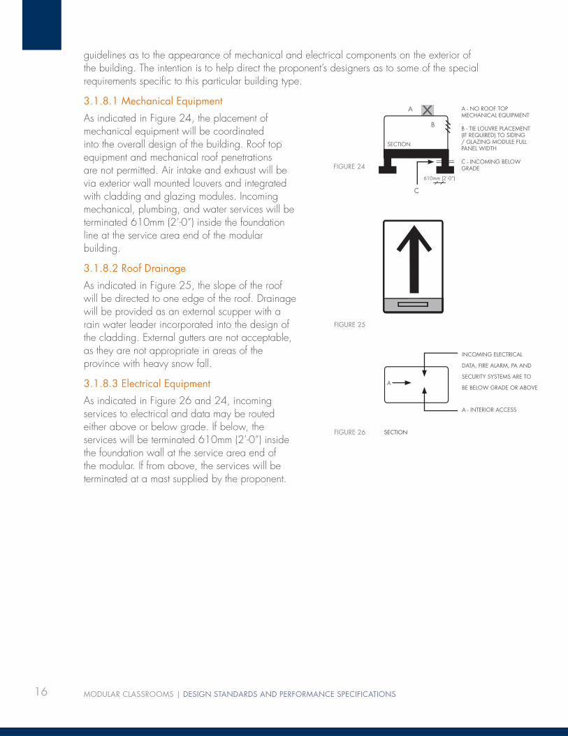
As indicated in Figure 24, the placement of mechanical equipment will be coordinated into the overall design of the building. Roof top equipment and mechanical roof penetrations are not permitted. Air intake and exhaust will be via exterior wall mounted louvers and integrated with cladding and glazing modules. Incoming mechanical, plumbing, and water services will be terminated 610mm (2’-0”) inside the foundation line at the service area end of the modular building.
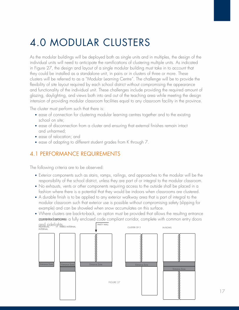
3.1.8.2 Roof Drainage
As indicated in Figure 25, the slope of the roof will be directed to one edge of the roof. Drainage will be provided as an external scupper with a rain water leader incorporated into the design of the cladding. External gutters are not acceptable, as they are not appropriate in areas of the province with heavy snow fall.
3.1.8.3 Electrical Equipment
As indicated in Figure 26 and 24, incoming services to electrical and data may be routed either above or below grade. If below, the services will be terminated 610mm (2’-0”) inside the foundation wall at the service area end of the modular. If from above, the services will be terminated at a mast supplied by the proponent.
FIGURE 26 SECTION
INCOMING ELECTRICAL
DATA, FIRE ALARM, PA AND
SECURITY SYSTEMS ARE TO
BE BELOW GRADE OR ABOVE
A - INTERIOR ACCESS
A
FIGURE 24
SECTION
X A - NO ROOF TOP MECHANICAL EQUIPMENT
B - TIE LOUVRE PLACEMENT (IF REQUIRED) TO SIDING / GLAZING MODULE FULL PANEL WIDTH
C - INCOMING BELOW GRADE
A
B
FIGURE 25
C
610mm (2’-0”)
17
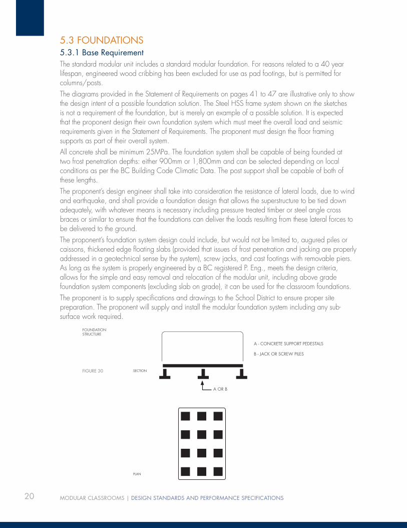
4.0 MODULAR CLUSTERSAs the modular buildings will be deployed both as single units and in multiples, the design of the individual units will need to anticipate the ramifi cations of clustering multiple units. As indicated in Figure 27, the design and layout of a single modular building must take in to account that they could be installed as a standalone unit, in pairs or in clusters of three or more. These clusters will be referred to as a “Modular Learning Centre”. The challenge will be to provide the fl exibility of site layout required by each school district without compromising the appearance and functionality of the individual unit. These challenges include providing the required amount of glazing, daylighting, and views both into and out of the teaching area while meeting the design intension of providing modular classroom facilities equal to any classroom facility in the province.
The cluster must perform such that there is:• ease of connection for clustering modular learning centres together and to the existing
school on site;• ease of disconnection from a cluster and ensuring that external fi nishes remain intact
and unharmed; • ease of relocation; and• ease of adapting to different student grades from K through 7.
4.1 PERFORMANCE REQUIREMENTS
The following criteria are to be observed:
• Exterior components such as stairs, ramps, railings, and approaches to the modular will be the responsibility of the school district, unless they are part of or integral to the modular classroom.
• No exhausts, vents or other components requiring access to the outside shall be placed in a fashion where there is a potential that they would be indoors when classrooms are clustered.
• A durable fi nish is to be applied to any exterior walkway area that is part of integral to the modular classroom such that exterior use is possible without compromising safety (slipping for example) and can be shoveled when snow accumulates on this surface.
• Where clusters are back-to-back, an option must be provided that allows the resulting entrance zone to become a fully enclosed code compliant corridor, complete with common entry doors and sidelights.
Entrance Zone Entrance Zone
INDIVIDUALINTERNAL
PAIRED INTERNAL
CLUSTERING OPTIONS
PARTY WALLIN ROWS
Entrance Zone
Entrance Zone
FIGURE 27
Entrance Zone
CLUSTER OF 3

18 MODULAR CLASSROOMS | DESIGN STANDARDS AND PERFORMANCE SPECIFICATIONS
BLANK FOR PAGINATION

19
5.0 STRUCTURAL REQUIREMENTS5.1 CODES AND STANDARDSComply with all applicable codes and standards including, but not limited to:
• .1 The British Columbia Building Code, 2006 Edition, Part 4, and Supplement #4• .2 CSA A23.3 – 04 Design of Concrete Structures• .3 CSA S16.1-2005 Design of Steel Structures• .4 CSA 086.1 – 2005 Engineering Design in Wood
5.2 DESIGN INTENT5.2.1 The intent of this project is to produce a repetitive freestanding classroom structure that is both permanent or relocatable in nature. It may be installed indefi nitely at any particular location or it may be moved in modular sections to any location in British Columbia. Accordingly, these units will be designed for the maximum snow load in any municipality, and the maximum seismic load that will be encountered at any geographic location.
The following criteria will be considered as part of these maximums:
• The roof snow load, 0.8Ss + Sr is to be 3.0 kPa for Vancouver Island and the Lower Mainland and 8.0 kPa for all other locations. This precludes the use of these classrooms in one municipality, Stewart, BC, and where this snow load is exceeded in non-municipal areas, e.g. Rogers Pass Summit
• The design 1:50 year hourly wind pressure shall be 0.75 kPa• The design dead load shall be as determined by the design engineer but not less
than 0.85 kPa• The assumed site class for seismic considerations need not be considered as worse than
Class D. The allowable bearing for footings shall be assumed as 100 kPa• The Importance factor is I = 1.3, for schools• The PGA should be considered as 0.62 and the design data for seismic loads shall be those
for Victoria• When calculating seismic base shear, the combination of maximum snow load and
maximum seismic zone never occurs together. The calculation of base shear in high seismic zones need not exceed 25% of 2.4 kPa. The value of 2.4 kPa includes the seismic importance factor of 1.15
5.2.2 The detailed design of the modular buildings and their foundations shall be carried out under the seal of a professional engineer registered in BC. The diagrams provided are to show the design intent. Methods of a manufacturer shall consider the constraints imposed by the transport of the classroom units.
5.2.3 Shop drawings, bearing the professional engineer’s seal, shall be submitted for all structural components of the classrooms prior to construction in order for the owner’s representatives to review the proposed building for general conformance to this specifi cation. These drawings, once approved, are to be forwarded to the school districts, to prepare the specifi c site and to provide foundations, if applicable.
20 MODULAR CLASSROOMS | DESIGN STANDARDS AND PERFORMANCE SPECIFICATIONS
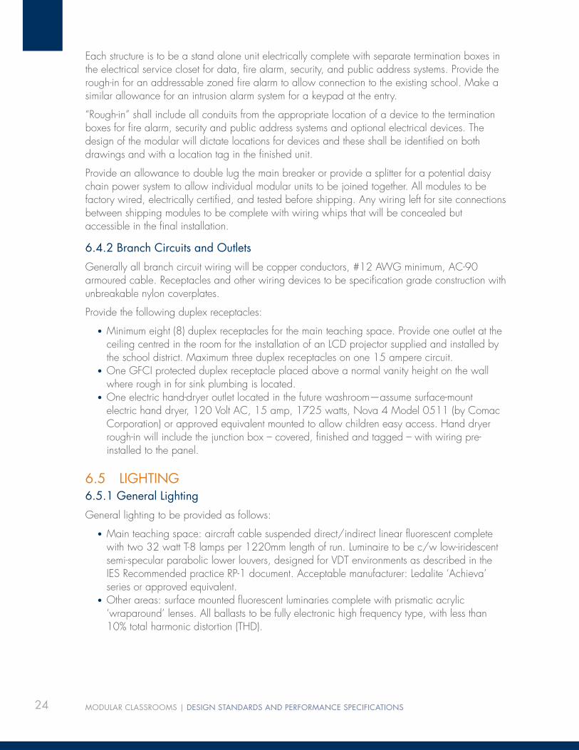
5.3 FOUNDATIONS5.3.1 Base RequirementThe standard modular unit includes a standard modular foundation. For reasons related to a 40 year lifespan, engineered wood cribbing has been excluded for use as pad footings, but is permitted for columns/posts.The diagrams provided in the Statement of Requirements on pages 41 to 47 are illustrative only to show the design intent of a possible foundation solution. The Steel HSS frame system shown on the sketches is not a requirement of the foundation, but is merely an example of a possible solution. It is expected that the proponent design their own foundation system which must meet the overall load and seismic requirements given in the Statement of Requirements. The proponent must design the fl oor framing supports as part of their overall system.All concrete shall be minimum 25MPa. The foundation system shall be capable of being founded at two frost penetration depths: either 900mm or 1,800mm and can be selected depending on local conditions as per the BC Building Code Climatic Data. The post support shall be capable of both of these lengths. The proponent’s design engineer shall take into consideration the resistance of lateral loads, due to wind and earthquake, and shall provide a foundation design that allows the superstructure to be tied down adequately, with whatever means is necessary including pressure treated timber or steel angle cross braces or similar to ensure that the foundations can deliver the loads resulting from these lateral forces to be delivered to the ground.The proponent’s foundation system design could include, but would not be limited to, augured piles or caissons, thickened edge fl oating slabs (provided that issues of frost penetration and jacking are properly addressed in a geotechnical sense by the system), screw jacks, and cast footings with removable piers. As long as the system is properly engineered by a BC registered P. Eng., meets the design criteria, allows for the simple and easy removal and relocation of the modular unit, including above grade foundation system components (excluding slab on grade), it can be used for the classroom foundations. The proponent is to supply specifi cations and drawings to the School District to ensure proper site preparation. The proponent will supply and install the modular foundation system including any sub-surface work required.
FIGURE 30
A - CONCRETE SUPPORT PEDESTALS
B - JACK OR SCREW PILES
FOUNDATIONSTRUCTURE
SECTION
A OR B
PLAN

21
5.3.2 Option for Selection By School District
School Districts may chose to have the modular unit delivered without a foundation system. In such an instance, the School District will be responsible for providing temporary or permanent foundations in a manner that matches the bearing locations and pressures specifi ed by the modular manufacturer and meets all applicable building codes. The proponent must supply suffi cient information as to loading, anchor locations and a list of required components that must be in place to accept the modular unit for those School Districts that opt out of the modular foundation and are providing the foundation for the modular themselves.
5.4 SUPERSTRUCTURE5.4.1 The superstructure drawings shall be read in conjunction with the architectural drawings and specifi cations with regard to material thicknesses, dimensions, and special requirements.
5.4.2 The drawings in the appendix are shown for the purposes of illustration only. The proponent shall develop their own plans and specifi cations for a structure that can be transported on provincial highways and municipal roadways in conformance with available clearances, widths, and all governing regulations regarding transportation on roadways.
5.4.3 Although some units may be in place indefi nitely, all units must be capable of simple disassembly and shall be moved in a reasonable number of pieces. Complete disassembly and reassembly will not be considered as a viable option.
5.4.4 Reasonable access must be built into the units to allow for whatever is required (bolt and tiedown anchor removal, service disconnection, etc.) to effect the relocation of the units at a later date.
5.4.5 All framing must be in accordance with the requirements of part 4 of the BC Building Code.
5.4.6 Wood shall be used for all structural components as permitted by the building code.
5.4.7 Wood framing materials shall be at least S-Dry, or preferably kiln dried material, with a maximum moisture content of 19% at the time of installation.
5.4.8 All material for beams and truss chords shall be Parallam as produced by Weyerhaeuser or an approved equivalent. Wood products shall be used as much a possible, except when precluded by load considerations. The roof trusses shown in Figure 30 (i.e. Parallam with cable and kingpost) convey the architectural design intent, which is to provide a stimulating exposed roof structure that does not require a suspended ceiling for concealment. Alternatives using tongue and groove timber deck that allow the trusses to be spaced further apart are acceptable providing a plywood overlay over the decking is provided to ensure a proper diaphragm.
FIGURE 31
ROOF STRUCTURE
SECTION
A - DROPPED BEAM OR CENTRAL TRUSS
B - TRUSS TENSION ROD (IF REQUIRED)
MIN. 2.4M (8’-0”) CLEAR INSIDE DIMENSION
AB

22 MODULAR CLASSROOMS | DESIGN STANDARDS AND PERFORMANCE SPECIFICATIONS
BLANK FOR PAGINATION

23
6.0 ELECTRICAL REQUIREMENTS6.1 INTRODUCTIONThis document has been prepared to outline the electrical requirements for a modular classroom building that can be installed at any school site in British Columbia. All classroom electrical systems shall provide energy-saving lighting controls and provide energy management solutions as described in item 6.5.4 consistent with the sustainable objectives of this modular program.
6.2 REGULATIONS AND STANDARDSElectrical systems must be in accordance with, and not limited to, the following standards and guidelines:
• Canadian Electrical Code – Current Edition• Local and Municipal By-laws• Illuminating Engineering Society (IESNA) recommendations
6.3 SITE SERVICESModular units will have the potential for either underground or overhead connection of power, data, fi re alarm, security, and public address systems and services as identifi ed in the Site Information Sheets.
All electrical services to be terminated in an electrical closet complete with lockable double doors accessible from within the modular building. If below, the services will be terminated 610mm (2’- 0”) inside the foundation wall at the service area end of the modular. If from above, the services will be terminated at a weather protected mast supplied by proponent.
Base Requirement
Service connections shall be provided to connect to underground services.
Option For Selection By School District
A weatherhead is to be provided to connect to over head services.
6.4 ELECTRICAL SYSTEMS6.4.1 Electrical Distribution
Each modular structure is typically split into several modules for shipping and/or construction. One of the modules is designated the (electrical) service module and should contain an electrical service panelboard located in an electrical service closet, complete with lockable double doors.
Panelboard to be as follows:
• 100 ampere service entrance type main breaker minimum 12 circuit• Commercial quality with lockable hinged door and type-written directory• Bolt-on type breakers• 120/240 volt, single phase, 3 wire to suit the circuits and 25% space for future loads• Acceptable manufacturers: Eaton Cutler Hammer, Square D, Siemens, and GE
24 MODULAR CLASSROOMS | DESIGN STANDARDS AND PERFORMANCE SPECIFICATIONS
Each structure is to be a stand alone unit electrically complete with separate termination boxes in the electrical service closet for data, fi re alarm, security, and public address systems. Provide the rough-in for an addressable zoned fi re alarm to allow connection to the existing school. Make a similar allowance for an intrusion alarm system for a keypad at the entry.
“Rough-in” shall include all conduits from the appropriate location of a device to the termination boxes for fi re alarm, security and public address systems and optional electrical devices. The design of the modular will dictate locations for devices and these shall be identifi ed on both drawings and with a location tag in the fi nished unit.
Provide an allowance to double lug the main breaker or provide a splitter for a potential daisy chain power system to allow individual modular units to be joined together. All modules to be factory wired, electrically certifi ed, and tested before shipping. Any wiring left for site connections between shipping modules to be complete with wiring whips that will be concealed but accessible in the fi nal installation.
6.4.2 Branch Circuits and Outlets
Generally all branch circuit wiring will be copper conductors, #12 AWG minimum, AC-90 armoured cable. Receptacles and other wiring devices to be specifi cation grade construction with unbreakable nylon coverplates.
Provide the following duplex receptacles:
• Minimum eight (8) duplex receptacles for the main teaching space. Provide one outlet at the ceiling centred in the room for the installation of an LCD projector supplied and installed by the school district. Maximum three duplex receptacles on one 15 ampere circuit.
• One GFCI protected duplex receptacle placed above a normal vanity height on the wall where rough in for sink plumbing is located.
• One electric hand-dryer outlet located in the future washroom—assume surface-mount electric hand dryer, 120 Volt AC, 15 amp, 1725 watts, Nova 4 Model 0511 (by Comac Corporation) or approved equivalent mounted to allow children easy access. Hand dryer rough-in will include the junction box – covered, fi nished and tagged – with wiring pre-installed to the panel.
6.5 LIGHTING6.5.1 General Lighting
General lighting to be provided as follows:
• Main teaching space: aircraft cable suspended direct/indirect linear fl uorescent complete with two 32 watt T-8 lamps per 1220mm length of run. Luminaire to be c/w low-iridescent semi-specular parabolic lower louvers, designed for VDT environments as described in the IES Recommended practice RP-1 document. Acceptable manufacturer: Ledalite ‘Achieva’ series or approved equivalent.
• Other areas: surface mounted fl uorescent luminaries complete with prismatic acrylic ‘wraparound’ lenses. All ballasts to be fully electronic high frequency type, with less than 10% total harmonic distortion (THD).

25
Average lighting levels to comply with the following IES guidelines:
• Classrooms: 500 lux• Hallways/Washrooms/Utility Rooms: 300 lux
The luminaries are to be installed parallel to the line of sight so that the side of the luminaire with the lowest brightness is in the line of sight. High colour rendering T8 fl uorescent lamps with a colour temperature of 3,500K and a colour rendering index (CRI) greater than 80 to be provided.
6.5.2 Emergency Lighting
Emergency lighting and exit signs to be provided to comply with the BC Building Code, and the local inspection authority. Notwithstanding the code requirement above, provide one self contained emergency battery unit complete with two 12-watt quartz halogen lamp heads located in each teaching space. The emergency battery is to be connected to the circuit serving the general lighting in the area. Provide one exit sign wall mounted above all exterior doors deemed as exits, and connected to a dedicated 120 volt circuit and also the emergency battery unit. The EXIT sign to utilize LED light source and comply with CAN/CSA C-860 standard. In the event of a failure of the normal lighting system, the emergency lighting and exit sign circuits must be automatically energized from battery power.
6.5.3 Exterior Lighting
Provide two vandal-resistant wall mounted luminaires located on the exterior wall, one adjacent to the exterior door and one on the opposite exterior wall Luminaire to use two 13-watt compact fl uorescent lamps and electronic ballast. There are to be no visible exterior screws.
6.5.4 Lighting Control
Luminaires in the teaching areas are to be controlled by a dual technology occupancy sensor confi gured to turn lights off when the room is unoccupied with a minimum of two local wall mounted override switches.
Luminaires will be turned on by the occupant via wall or low voltage switching lighting will be turned off after no occupancy has been detected for 30 minutes. The minimum on time for lighting is 60 minutes and the minimum off time is 0 minutes.
Lighting in other areas such as washrooms and utility rooms are to be controlled via wall mounted occupancy sensors. The exterior luminaire is to be controlled via a local photocell with an override switch located in the interior of the building, adjacent to the exterior door.
6.6 TELEPHONEA telephone outlet is to be provided on the wall adjacent to the teaching wall at 1,400mm above the fi nished fl oor. Provide one category 6 cable from this outlet to a BIX block located in the electrical closet.
26 MODULAR CLASSROOMS | DESIGN STANDARDS AND PERFORMANCE SPECIFICATIONS
6.7 FIRE ALARM SYSTEMProvide the rough-in as previously defi ned for an addressable single-stage fi re alarm system in each building. Allow rough-in for the following devices:
• Fire (rate of change) detectors in each room• Manual pull station adjacent to the exterior door• Fire alarm bell and strobe light located in the main teaching area• Connections to the sprinkler fi re protection alarm and trouble devices• Smoke detectors in each room
All devices will be installed by the school districts in accordance with ULC S-524.
6.8 DATA CABLINGA simple data cabling system is to be provided in the building consisting of RJ45 jacks and nonmetallic wall plates connected via category 6 cables terminating on a BIX block located in the electrical closet. Provide six (6) data outlets, located adjacent to the duplex power receptacles at the walls and one data outlet at the ceiling in the centre of the room for an LCD projector installation by the school district. Provide conduit and terminal boxes to provide computer connection from the overhead area at the LCD projector to a point 250mm above the fl oor on the teaching wall.
6.9 PUBLIC ADDRESSProvide for one surface wall mounted loudspeaker located on the teaching wall. Provide a shielded twisted pair #18 AWG cable from the loudspeaker to a BIX block termination point in the electrical closet and the possibility of a PA System based on the telephone itself. The wall mounted loudspeaker shall be capable of two-way conversation.
6.10 INTRUSION ALARMProvide rough in as previously defi ned for an intrusion alarm system to detect unauthorized individuals entering the building. Allow for a system that will include door contacts, PIR motion detector(s), local siren, control panel with the capability of tying into the adjacent schools activation key-pad. Wiring for the motion detectors and door contacts will be home run to the electrical closet.
6.11 RFTV CABLINGProvide one RG-6 coaxial cable from an outlet located at the teaching wall, terminating in the electrical closet.
6.12 POWER ROUGH IN FOR HAND DRYER AND AUTO FAUCETRough in as previously defi ned for all sink locations with auto faucets, and hand dryer in potential washroom only. Dryer rough-in to be located within 1,525mm (5’-0”) of the potential sink location.
6.13 MECHANICAL EQUIPMENT WIRINGPower wiring for mechanical equipment to be provided.

27
7.0 MECHANICAL REQUIREMENTS7.1 INTRODUCTIONThe following document has been prepared to provide an overview and guideline specifi cation for the mechanical, plumbing, and fi re protection systems that will be installed in the modular classroom building. It is intended that the systems will be suitable for any school site location throughout British Columbia.
7.2 CODES AND STANDARDS In addition to meeting the following codes and standards the mechanical and plumbing systems installed must meet minimum energy performance standards of ASHRAE 90.1 - 2007.
All work shall be in accordance with the regulations of the following authoritative bodies, the codes in effect at the time of tender, and any others having jurisdiction:
• Fire Marshall• Canadian Electrical Code• 2006 BC Building code and local building by-laws• Worker’s Compensation Board Standards• Canadian Standards Association• BC Refrigeration Code and C.S.A. codes governing refrigeration plants• BC Gas Code• Canadian Gas Code B-149.1• 2006 B.C. Plumbing Code• BC Boiler and Pressure Vessel Act• National Fire Protection Association NFPA 13• Underwriters’ Laboratories of Canada
7.3 DESIGN CONDITIONS7.3.1 The design intent is to provide a heating and cooling system for each modular building, which will be capable of maintaining the following indoor temperature targets for all climatic regions in British Columbia.
7.3.2 Indoor design temperatures to be as per the following:
• Classroom 75 deg F Cooling (23.8 C) 71 deg F Heating (21.5 C)
7.3.3 Ventilation requirements as per ASHRAE 62-1989
• Classroom occupancy shall be 25 students• Provide for 20 CFM of outside air per person• Washroom exhaust provide a minimum of 15 Air changes per hour or 2 CFM
per square foot
7.3.4 Building envelope performance will be as per Section 3.0
7.3.5 Acoustic requirements as per ASHRAE standards
• Between classroom space and washrooms, NC–40

28 MODULAR CLASSROOMS | DESIGN STANDARDS AND PERFORMANCE SPECIFICATIONS
7.4 PLUMBING SYSTEMS7.4.1 Plumbing fi xtures will be provided and installed by the School District. The proponent shall provide rough-in piping and drains as required to allow the installation of 2 sinks in the classroom, water closet and sink in the proposed bathroom location and a janitor’s sink in the proposed janitor closet. All plumbing fi xtures will be of institutional quality and meet LEED® and Part 10 of the BC Building Code requirements for water conservation. The rough-in shall be comprised of piping to fi xtures, vents and all required connections from the water service entry location to the appropriate area where the ends shall be capped, covered and labelled. This applies equally to sanitary and storm drainage piping and connections.
7.4.2 Provide one non-freeze hose bibs at the building perimeter. Provide a drain and isolation valve at the water entry to the building.
7.4.3 Provide a complete water entry station complete with necessary isolation valves, back fl ow prevention and pressure regulation with normally closed bypass.
7.4.4 Provide Rough-in for a ceiling mounted electric hot water tank (5 gallon) at each washroom location complete with drain pan. Rough-In shall include a capped water supply line and a capped hot water line to supply the potential fi xtures as previously identifi ed as well as prewired electrical junction box to allow connection to the electrical system
7.4.5 All piping materials to meet the requirements of the BC Building Code. Provide isolation valves for ease of maintenance for each plumbing fi xtures.
7.4.6 Each modular building is to be provided with a 1” domestic cold water supply for water connection to all plumbing fi xtures.
7.4.7 Each modular building is to be provided with a 4” sanitary and 4” storm connection for all drainage requirements.
7.5 FIRE PROTECTION SYSTEMS7.5.1 It is intended to provide a complete fi re protection system for the building which hydraulically will function at all school sites throughout British Columbia with varying water pressure availability.
7.5.2 Provide complete sprinkler piping system to NFPA No. 13 224, and local municipal by-laws and requirements. In addition, to comply with owner’s insurance authority requirements. All material shall be listed by ULC or approved for sprinkler/standpipe use. Pipe sizing by hydraulic calculations.
7.5.3 Since the modular building will be installed at various sites throughout the province the piping is to be generously sized to deal with low water pressure fl ow and availability. The assumptions are to be stated on the hydraulic design drawings.
7.5.4 Run all piping concealed. Piping subject to freezing to be insulated and heat traced. Coordinated this requirement with the electrical requirements.
7.5.5 Design standards:
• Light hazard occupancy

29
7.5.6 Coordinate sprinkler head locations with the refl ected ceiling plan and center heads on the ceiling tiles. Coordinate sprinkler head locations with other ceiling mounted devises such as lights and diffusers.
7.6 HVAC SYSTEMS7.6.1 The building HVAC system will consist of a stand alone classroom ventilator which is capable of providing full heating and cooling to the space. The unit ventilator shall be a vertical standalone air source heat pump such as an “Airdale Classmate HE Series” or approved equivalent. The unit ventilator will be arranged to provide ventilation, heating and cooling with a discharge air plenum located directly above the wardrobe unit.
7.6.2 Every heat pump will be complete with a supplementary electric resistance heating coil and a hot water heating coil. The heating water piping is to be run from the unit ventilators heating water coil to the mechanical closet. The piping will be valved and capped for the heating water connection option. See the schematic drawing MSK-1 below.
7.6.3 The heating and cooling capacity of the unit ventilator is to be sized to provide temperature control at all climate locations in the British Columbia region.
7.6.4 The system will include all ductwork distribution, diffusers, grilles, insulation and controls as required.
7.6.5 The air supply will be delivered through an acoustic lined discharge air plenum above the wardrobe unit. The supply diffusers are to be low noise (NC 25) double defl ection type diffusers. The plenum is to be a minimum of 4 meters in length. Return air will be taken back at low level in the unit ventilator and relief air will be at high level in the classroom and located at high level.
MSK-1 - Standalone Heat Pump Classroom Ventilator with Displacement Diffuser
30 MODULAR CLASSROOMS | DESIGN STANDARDS AND PERFORMANCE SPECIFICATIONS
Base Requirement
• The classroom ventilator will consist of a standalone vertical dx-heat pump with built-in evaporator and condenser coils capable of providing full heating and cooling. Back-up heating will be provided with electric resistance heating. The condenser is built into the unit as a single package. Exterior louvers will be used for both outside air intake and the condenser/evaporator operation.
• The suggested manufacturer which will meet performance criteria is the Airedale Classmate HE – 3.0 tons nominal capacity. The air fl ow shall be 570 L/s.
• With the base system, back-up heating can be provided in two ways as follows: Option 1: Use the supplementary electric heating coil supplied with heat pump Option 2: Use the supplementary hot water coil by connecting to a school’s existing hot
water boiler system
Option for Selection By School District
In locations where electrical power supply at a school site is limited and there is no ability to connect to an existing hot water system at a school, then a boiler will be Installed in the modular classroom. These shall allow for alternate fuel sources as follows:
• Option 3: Boiler with Gas orifi ce• Option 4: Boiler with Propane orifi ce
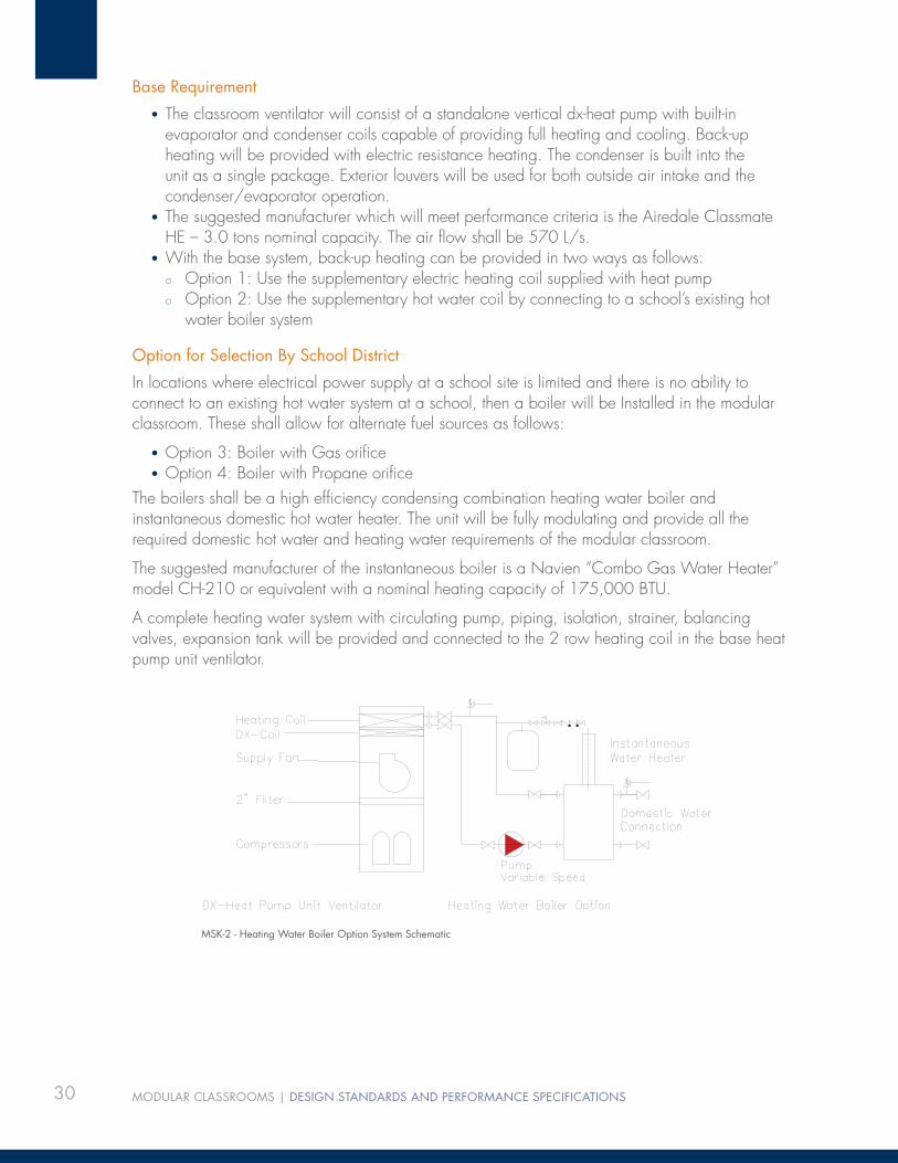
The boilers shall be a high effi ciency condensing combination heating water boiler and instantaneous domestic hot water heater. The unit will be fully modulating and provide all the required domestic hot water and heating water requirements of the modular classroom.
The suggested manufacturer of the instantaneous boiler is a Navien “Combo Gas Water Heater” model CH-210 or equivalent with a nominal heating capacity of 175,000 BTU.
A complete heating water system with circulating pump, piping, isolation, strainer, balancing valves, expansion tank will be provided and connected to the 2 row heating coil in the base heat pump unit ventilator.
MSK-2 - Heating Water Boiler Option System Schematic

31
7.7 CONTROL SYSTEMS – DDC7.7.1 Provide a complete and standalone DDC Control System for each modular building. The DDC system is to be provided with an Ethernet connection, which can be networked through a BACNET connection to all existing school site and school district site control systems.
• DDC control system to provided with full graphics for the controls installed• The DDC control panel to be mounted inside the mechanical room in each modular building
7.7.2 All remote DDC wiring to be installed as per the Canadian Electrical Code
7.7.3 The following DDC points shall be provided for the control system.
Descriptor NameDigital Analog
Input Output Input OutputVentilator Enable RMotor Status CTOutside Air Damper DMADamper End Switch ES DMAReturn Air Damper DMARelief Air Damper DMADamper End Switch ES DMARoom Temperature RTSDuct Discharge Temp DTSCooling Enable RHeating Enable RFilter Status FILOutside Air Temp OATCO2 Sensor CO2Occupancy Sensors (2) OCOptional Points:Boiler Enable RBoiler Water Reset Temp RPump Status CTWater Temperature WTS3-way Control Valve VMAFreeze Stat FRZ (Hard Wire) VMA

32 MODULAR CLASSROOMS | DESIGN STANDARDS AND PERFORMANCE SPECIFICATIONS
7.7.4 Sequence of Operation:
• Morning warm-up in classroom shall be by means of heating the air to required supply temperature.
• Fan system shall be started based on occupancy sensor control, override, CO2 levels and weekly schedule. The fan system will be used to primarily provide room ventilation, cooling, and heating.
• Modulate the mixing dampers in sequence with dx heat pump heating mode and either electric back-up or hot water heating water control valve or dx-cooling mode to provide the required supply air discharge temperature. Discharge air temperature shall be maintained between 16 to 28°C.
• When outdoor air temperatures permit, modulate the dampers to provide free cooling to the space, if cooling is required. Cooling discharge air temperature shall be no lower than 16°C for displacement ventilation.
• The outside air and return air damper shall be modulated in sequence with the remote relief air damper.
• The room carbon dioxide sensor is to maintain maximum carbon dioxide level of• 1,000ppm in the system. If carbon dioxide levels exceed the setpoint value (adjustable
the outdoor air dampers are to modulate open to bring the carbon dioxide levels down to within setpoint levels. Minimum outside damper position shall be 5% open regardless of CO2 levels. (CO2 failure pre-caution).
• The unit shall remain off during night set back, unit shall be started and stopped to maintain night set back temperatures.
• Freeze-stat (hard-wired) located downstream of the heating coil shuts down fan and activates DDC alarm.
Occupancy Sensors:
• Shall be used to control unit stop/start and lighting operation. A minimum of 2 sensors in each classroom is required (Sensors to be Paradox Digital Vision 525 D (dual technology) c/w swivel mounting bracket and protective guard.
• The occupancy sensor shall not be used to turn on the lighting. Lighting will be turned on by the occupant via wall or low voltage switching. Lighting will be turned off after no occupancy has been detected for 30 minutes. The minimum on time for lighting is 60 minutes and the minimum off time is 0 minutes.
• Upon a signal from the occupancy sensor for 15 minutes, start the associated unit ventilator and run in normal occupied operation mode. The minimum off time of the unit ventilator is 30 minutes and the minimum on time of the unit ventilator is 30 minutes. When no occupancy has been detected for 30 minutes turn off the unit ventilator.
• When the unit ventilator is off and there is no occupancy, and we are still on the weekly schedule, the room shall be controlled to an ‘un-occupied set-point’ temperature of 19°C in heating season when outside air is below 19°C and to 26°C in cooling season when the outside air temperature is above 26°C.

33
8.0 APPENDIX AROLLING SHUTTERS AND SCREENSPLEASE NOTE : This specifi cation references Talius rollshutters and vandel proof screens. These are to be read as “Talius or approved equivalent”.
A.1 Rollshutters
.1 Curtain:
The rollshutter curtain is to be made from individual rollformed aluminum profi les with an injected super-hard resin foam core and shall have a cover width of 38mm (1 1/2”) and a thickness of 9mm (11/32”). Minimum aluminum gauge to be 0.62mm (0.0244”). Finish to be baked-on enamel with a dry fi lm thickness of at least 0.05mm (0.0020”). The minimum weight per square metre is to be 8.0 kg (0.0114 lbs/inch2). Manufacturer’s description: SAFE MINI. Alternate slats are to be fi tted with inserts to hold the curtain in alignment. The bottom of the curtain shall be fi nished with an extruded aluminum bar and fi tted with a sealing bottom vinyl strip.
.2 Guide Rails:
The guide rails are to be minimum 0.065” or 1.60mm gauge aluminum extrusions fi tted with two noise and weather insulating strips. All guide rails must have undergone a multiple stage pretreatment procedure and be painted with a baked-on paint. Guide rails to be acid, alkali and oil resistant. The guide rail is to be made of two snap-together parts that prevent unauthorized access to the mounting screws. Curtain penetration into the guide rail shall be at least 41mm (1 5/8”) for sections less than 1.83m (72”) in width and at least 66mm (2 5/8”) for sections over 1.83m (72”) in width. Manufacturer’s description: SAFE RAIL, and SAFE-40 RAIL respectively.
On rollshutter sections where width dimensions exceed 3.05m (120”), split the rollshutter into two or more sections by means of a centre guide rail(s). Manufacturer’s description: SAFE CENTRE RAIL.
.3 Sill:
If applicable, provide a 30mm x 47mm (1 1/8” x 1 13/16”) U-shaped aluminum sill to hold the curtain securely in placed when closed, achieving 1 3/8” penetration. The side wall thickness is to be minimum 0.080” or 2mm gauge aluminum to reduce prying damage.
Manufacturer’s description: SAFE U-SILL. Where the U-sill is exposed to weather, drill a minimum of two “weep” holes in the inside channel of the U-sill to allow for moisture drainage.
.4 Build-Up:
If applicable, provide heavy-gauge aluminum build-up underneath the guide rails, along the panel box top, panel box bottom, and sill. Unless otherwise specifi ed, the width of the build-up is to be 35mm (1 3/8”), depth to be suitable to provide obstruction-free operation of the rollshutter curtain.
34 MODULAR CLASSROOMS | DESIGN STANDARDS AND PERFORMANCE SPECIFICATIONS
.5 Panel Box Housings:
Panel boxes are to be precision rollformed from 1.0 - 1.2mm (0.040” - 0.0472”) aluminum with an electro-statically bonded and baked fi nish. Lower half of the panel box must be detachable for future servicing access. Panel box service panel to be secured with tamper-resistant fasteners on all panel boxes less than 2.13m (7’) off the ground. Protective fi lm to be removed upon installation of module. Please note that custom painted panel boxes will not have protective adhesive plastic fi lm. All panel box endplates to be manufactured by pressure die-casting procedure from high grade aluminum alloy. Endplates must be chromed and laminated with a resistant PVC surface.
Panel box style to be 5-corner. Panel box sizes to suit rollshutter dimensions. All panel boxes are to be CSA or UL certifi ed and have a grounding lug mounted on the inside of the endplate.
.6 Colour Selection:
Unless otherwise indicated, items to be selected from manufacturer’s standard colour range:
• curtain• bottom curtain profi le• guide rails• sill• aluminum build-up• panel box housing
.7 Operation Individual Control:
The rollshutters shall be electrically operated. Provide a tubular 120 VAC motor installed inside the shaft. The motor unit shall be constructed with solenoid brakes, thermal overload protection switch with automatic reset and enclosed, and permanently lubricated bearings and gears. All electrical components to be C.S.A. and U.L.C certifi ed. Each motor unit shall be controlled by a momentary-contact, three position switch. All switches to fi t standard electrical boxes. Locations for switches are to be determined by proponent’s design as shown on proponents drawings. All wiring and installation of switches to be as per manufacturer’s instructions and to meet local electrical code requirements. All motors must have a three-wire quick disconnect installed inside of the panel box end plate. The ground wire is to be grounded to the panel box end plate grounding lug.
Unless otherwise indicated, electrically operated rollshutters shall include Talius electrical disconnects. Talius multi-connection electrical disconnects are CSA approved to 300VAC and 15AMPS. The Talius multi connection electrical disconnects can be used for stranded and solid copper wire 22AWG to 12AWG. Talius multi connection electrical disconnects are for use by electricians to ensure continuity of wires between the male plug connected to the motor side of the electrical connection and the female plug connected to the switch or power side of the electrical connection.
.7 Operation Group Control
Rollshutters are to be group controlled and programmable to shut down after hours and automatically reopen when the classroom is in use, there will be one switch that controls all rollshutters on windows on the same elevation in each room. Each motor group shall be controlled by a momentary contact, three position switch and double throw multi-pole relay. Locations for motors, isolation control relays and switches, shall all be appropriate to the proponents intended design and shown on drawings. All switches to fi t standard electrical boxes.

35
All wiring as per manufacturer’s instructions and to local electrical code requirements. All motors must have a three-wire quick disconnect installed inside of the panel box end plate. The ground wire is to be grounded to the panel box end plate grounding lug.
Unless otherwise indicated, electrically operated rollshutters shall include Talius electrical disconnects. Talius multi connection electrical disconnects are CSA approved to 300VAC and 15AMPS. The Talius multi connection electrical disconnects can be used for stranded and solid copper wire 22AWG to 12AWG. Talius multi connection electrical disconnects are for use by electricians to ensure continuity of wires between the male plug connected to the motor side of the electrical connection and the female plug connected to the switch or power side of the electrical connection. All motor wire cables are to be cut to size on site and plugs to be installed by a certifi ed electrician.
.8 Locking Devices
All rollshutters shall be equipped with curtain hangers constructed of rust proofed spring steel and chromed bottom bars. All hangers must be painted to prevent chemical reaction with curtains. Hangers are to be installed at suffi cient intervals between shaft and curtain to prevent curtains to be lifted by more than 152 mm (6”) from the closed position, without the use of an operator. In addition, each rollshutter shall be equipped with two automatically locking and unlocking security devices. Each security device shall be installed in the upper curtain area and engage into a pair of ribbed-metal plates inside the guide rail. Each device shall consist of a single expansion-toothed chain and be triggered through movement of the curtain. Each security device shall prevent any lifting movement of the curtain except by means of the operator device.
.9 Anti-Graffi ti Coating
All Talius rollshutter curtains, guide rails, sills and panel boxes shall be coated with Talius Release non-sacrifi cial anti-graffi ti coating designed to allow for easy clean-up of graffi ti from the exposed rollshutter surfaces. Talius Release coating is a modifi ed aliphatic-polyurethane coating with enhanced abrasion resistance to provide resistance to chemicals, abrasions and impact. Talius Release is a clear coat that provides a gloss fi nish over stock and custom colors, and offers color retention and a non-stick surface. Talius Release coating is applied with a dry fi lm thickness of 1.0 – 2.0 mils (25-50 microns). Hardness: ASTM D3363, 2H. Solvent Resistance: ASTM D4752, 100 MEK rubs; NO failure. Abrasion Resistance: 1000 cycles CS-17, ASTM D4060, 32 mg loss. Impact Resistance: ASTM D2794, 40 in lbs; NO failure. Flexibility: ASTM D522, 1/8” mandrel blend; NO failure.
36 MODULAR CLASSROOMS | DESIGN STANDARDS AND PERFORMANCE SPECIFICATIONS
A.2 Security Screens
.1 Panel:
Perforated panels to be made from 6.35mm (1/4”) 3003 H14 aluminum sheet. Perforations to be die punched 6.35mm (1/4”) diameter holes, on 9.53mm (3/8”) centers, with 9.53mm (3/8”) offset rows. Panel openness factor to be 42%.
.2 Frame:
Frame members are to be made from 6065T5 aluminum extrusion with a wall thickness of 1.4mm (0.055”). Nominal size of the extrusion to be 38mm wide by 13mm high (1 1/2” x 1/2”). Frame extrusion to have a 19mm (3/4”) open channel for perforated panel penetration, and 19mm (3/4) hollow section for hardware mounting. Mounting-side of frame extrusion to incorporate two tracks for slide-on aluminum build-up.
.3 Build-Up:
If applicable, provide heavy-gauge aluminum build-up underneath the frame members on all four sides. Width of the build-up to be 35mm (1 3/8”), depth to be as specifi ed as per the Vandal Panel™ Schedule.
.4 Finish:
All Vandal Panel™ components to be cleaned, acid-etched, chromated, and custompainted with a pure two-component polyurethane paint system, using aliphatic isocyanate reacted with resin polyols. Minimum dry fi lm thickness to 2.5 mil (65 microns). Custom color to match required job specifi cations.
A.3 Installation
.1 Rollshutters, Vandal Panels™ and hardware as described herein shall be installed by approved rollshutter installers. Installers must be factory authorized and installation must proceed in accordance with manufacturer’s installation instructions.
.2 The rollshutter contractor to supply and use suitable mounting hardware for the mounting surface application, including hollow-wall and concrete anchors, where necessary. Mounting hardware size to be a minimum of #8 x 2”. Mounting hardware for the guide rails, build-up and U-sills to be installed between 20cm – 30cm (8” – 12”) on centers. Mounting hardware for the panel box to be installed between 40cm – 50cm (16” – 20”) on centers, horizontally along the top inside corner of the panel box, and each screw head to be supplemented with a large fl at washer to avoid tearing through the sheet aluminum. Each cast aluminum end plate on a panel box to be secured with one fastener to the mounting surface, two if the rollshutter curtain weight exceeds 22kg (50 lbs). When installation into brick or concrete surfaces is necessary, mounting hardware to be used shall be Tapcon style of suitable diameter and length.
.3 Install Rollshutters and Vandal Panels™ plumb, true, square and level, free from distortion or defects affecting appearance or performance. Adjust and test moving parts to ensure smooth operation.
.4 Suitable exterior caulking to be applied by the rollshutter contractor around the exterior perimeter of the completed rollshutter installation to prevent infi ltration of moisture, wind and debris behind the rollshutter when the curtain is fully closed.
.5 All work to be completed in a professional, safe and timely manner.
37
9.0 APPENDIX BDOORS AND HARDWAREThe following is a list of the basic hardware essentials for modular buildings. A complete installation shall include all required weather stripping and door thresholds. Only approved alternates will be considered.
EXTERIORDoors:
Provide an insulated hollow metal door at the building’s entrance.
Construction: 915mm W x 2,032mm H x 41mm thick (3’-0”W x 6’-8”H x 1 5/8” thick) 12gauge insulated hollow metal doors.
Frames:
16 gauge wrap around pressed steel frame.
Hardware:
4 pair tamper proof hinges or continuous hinge
VonDuprin 99 series panic rim devices with cylinder dogging
LCN 4111 series door closers
Hunter HA-8 door HDC door operators
Hess 9600 series electric strikes for FOB single doors
VonDuprin EL rim panic devices and EPTs (electric power transfer) on HDC/operator doors (no electric hinges)
1457 Schlage keyway on exterior devices (mullions, cylinder dogging, rim cylinders)
300mm (1’-0”) high stainless steel kick plates (both sides)

38 MODULAR CLASSROOMS | DESIGN STANDARDS AND PERFORMANCE SPECIFICATIONS
INTERIORDoors:
Storage, janitorial and mechanical doors to be 18 ga HMD tack welded. Classroom doors SCWD (solid core wood).
Hardware:
Base Requirement
Schlage ND70RHO locksets on classroom doors
Schlage ND80RHO on storage, mechanical and janitorial doors
Schlage ND40RHO locksets on staff WRs Schlage B663 deadbolts on student WR doors with push/pull hardware
LCN 4111 door closers 4 1/2 x 4 1/2 hinges (minimum 3 / door) Schlage “E” keyway on interior locks.
Cabinet hardware:
Schlage CL1000 “E” keyway cabinet locks on 3/4” cabinet doors -
CL1000 EXT - on 1 3/8” teacher cupboard doors - CL2000 locks on drawers.
Option for Selection By School District
Corbin hardware in similar confi guration. Quantities are identifi ed on the School Site Information Sheets.
39
10.0 APPENDIX CMILLWORK QUALITY STANDARDSC.1 References
AWI/AWMAC Quality Standards Illustrated (QS1), current edition.
C.2
Millwork shall at least conform to the “Quality Standards for Architectural Woodwork” of the “Architectural Woodwork Manufacturers of Canada (AWMAC), latest edition.” These specifi cations take precedence over AWMA-B.C. standards. Interior of cabinets when behind doors (AWMAC semi exposed) shall be Birch veneer to match case work. Tops of all cupboards to be fl ush and have plastic laminate fi nish. Flush overlay construction details shall be used.
C.3
Construct all cabinet work with plastic laminate fi nishes to AWMAC custom grade and cabinet work with exposed veneer face to AWMAC Premium grade unless specifi cally noted otherwise on details.
C.4
Plywood shall be used for all cabinet bodies and tops, gables, and shelves. Doors shall be made from MDF birch veneer.
C.5
Unless specifi cally noted otherwise on drawings, the following fi nishes shall apply:
.1 Plastic laminate to all countertops, splash, and counter edges .
. 2 All exposed surfaces shall be fi nished uniform in grain and colour with hardwood, with 3 mm PVC edging, and clear-coat fi nish. All semiexposed surfaces shall be fi nished with C-2 natural birch. Use MDF core for doors per AWMAC standards. Exposed fi nish ends in matching GP28 laminate .
.3 Cabinet interiors when behind doors shall be birch veneer to be birch veneer to match case work.
.4 Drawer interiors - polyurethane fi nished plywood or solid wood.
C.6
Miscellaneous trims shall be Premium Grade Quality for clear fi nish.
40 MODULAR CLASSROOMS | DESIGN STANDARDS AND PERFORMANCE SPECIFICATIONS
C.7 Inspection
.1 Architectural woodwork shall be manufactured and/or installed to AWMAC Quality Standards Custom Grade. Shop drawings shall be submitted for review or approval before any work is commenced. Where it is deemed necessary by the Architect, a sample cabinet (consisting of a minimum of 1 drawer, 1 door, showing precisely the materials, hardware, and the type of construction the manufacturer intends to use) shall be submitted for inspection. Proposed substitutions in materials or hardware must be detailed in writing and approved by the consultant before submission of shop drawings.
. 2 AWMAC to inspect all woodwork and casework for the fi rst modular building and prepare a complete report. Based on the report, alterations, if required, will be detailed into the work and form the minimum acceptable standards for all other modular buildings. Based on this standard, casework for one modular building for each school district will be inspected prior to shipment to each school district.
C.8 Qualifi cations
.1 Contractor and their personnel engaged in the work shall be able to demonstrate successful experience with work of comparable extent, complexity, and quality to that shown and specifi ed .
. 2 Manufacturers who are members in good standing of the Architectural Woodwork of the Architectural Woodwork Manufacturers Association of Canada (AWMAC) and are familiar with this Standard.
C.9 Provision of Guarantee
The architectural woodworker shall furnish the owner with a two (2) year AWMAC Guarantee Certifi cate, or a two (2) year maintenance bond, to the full value of the architectural woodwork sub-contract; certifying that the architectural woodwork has been manufactured and/or installed in accordance with the standards contained in the AWMAC Quality Standards Illustrated, latest edition. Those providing a maintenance bond instead of the Guarantee Certifi cate are to submit a letter from their insurer stating that they will provide the bond. A copy of this letter is to be attached to their tenders. The Guarantee shall cover replacing and/or refi nishing to make good any defects in architectural woodwork due to faulty workmanship or defective materials supplied by this architectural woodworker, which may appear during a two (2) year period following the date of substantial completion of the project.

41
11.0 APPENDIX DDEMONSTRATION STRUCTURAL DRAWINGSThis series of illustrations demonstrates two potential alternative approaches to structure.
The Proponent will complete their own design.
PLAN - ALT 1
ILLUST
RATIV
E ONLY

42 MODULAR CLASSROOMS | DESIGN STANDARDS AND PERFORMANCE SPECIFICATIONS
PLAN ALT 2
ILLUST
RATIV
E ONLY
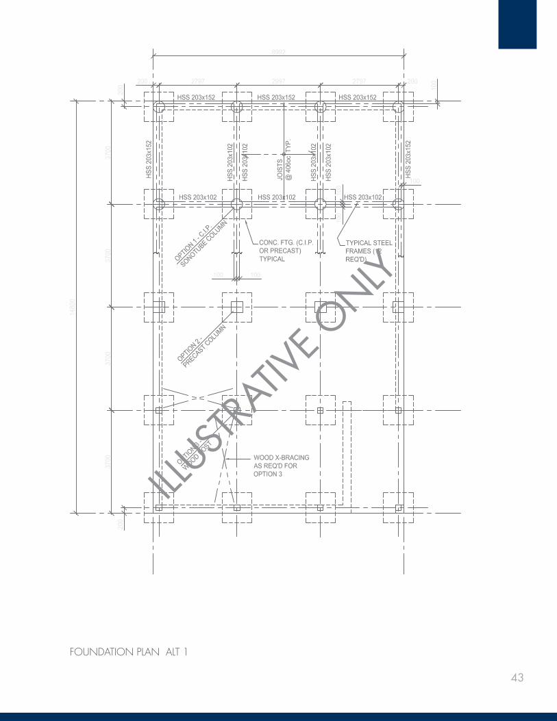
43
FOUNDATION PLAN ALT 1
ILLUST
RATIV
E ONLY
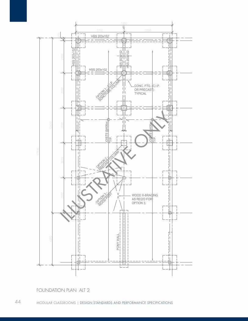
44 MODULAR CLASSROOMS | DESIGN STANDARDS AND PERFORMANCE SPECIFICATIONS
FOUNDATION PLAN ALT 2
ILLUST
RATIV
E ONLY

45
FOUNDATION SECTIONS
ILLUST
RATIV
E ONLY

46 MODULAR CLASSROOMS | DESIGN STANDARDS AND PERFORMANCE SPECIFICATIONS
FOUNDATION SECTIONS
ILLUST
RATIV
E ONLY
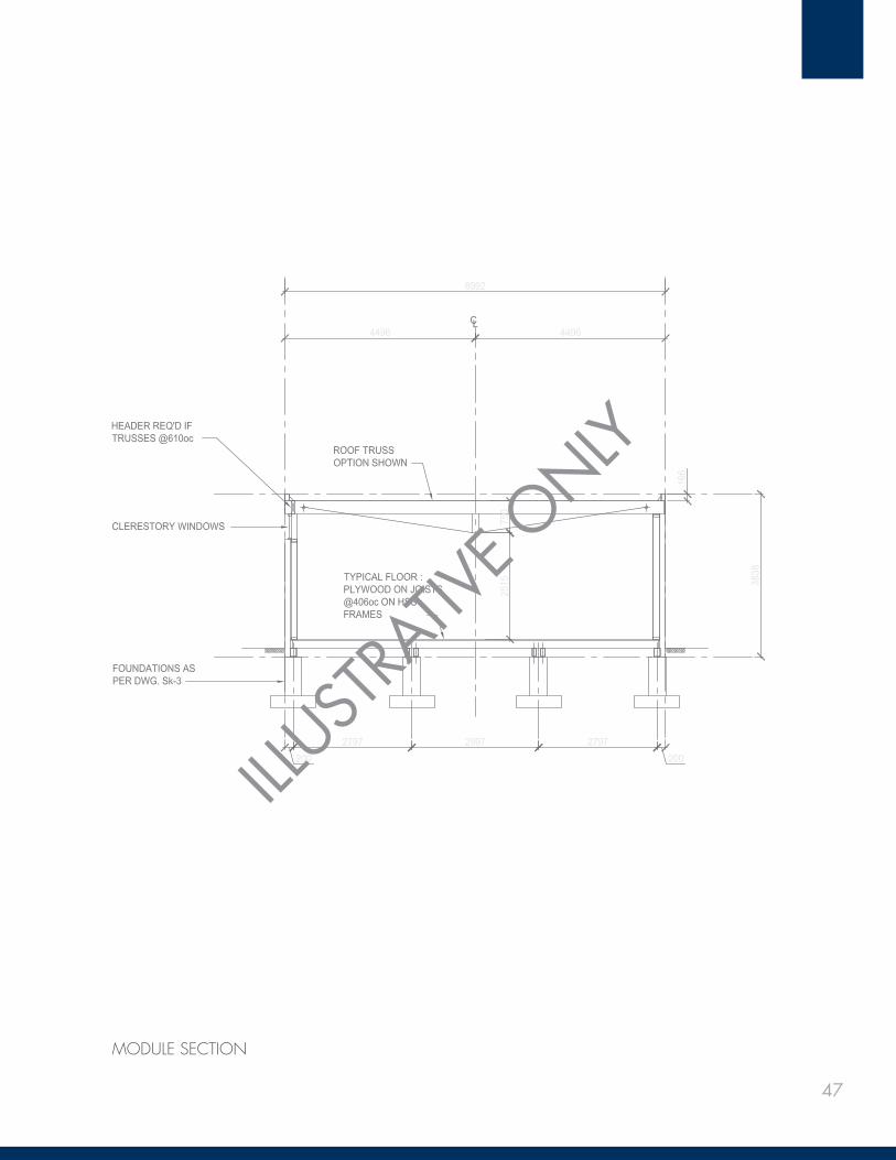
47
MODULE SECTION
ILLUST
RATIV
E ONLY

48 MODULAR CLASSROOMS | DESIGN STANDARDS AND PERFORMANCE SPECIFICATIONS
12.0 APPENDIX EINDICATIVE TEACHER’S WORK CABINET DETAILS
ILLUST
RATIV
E ONLY
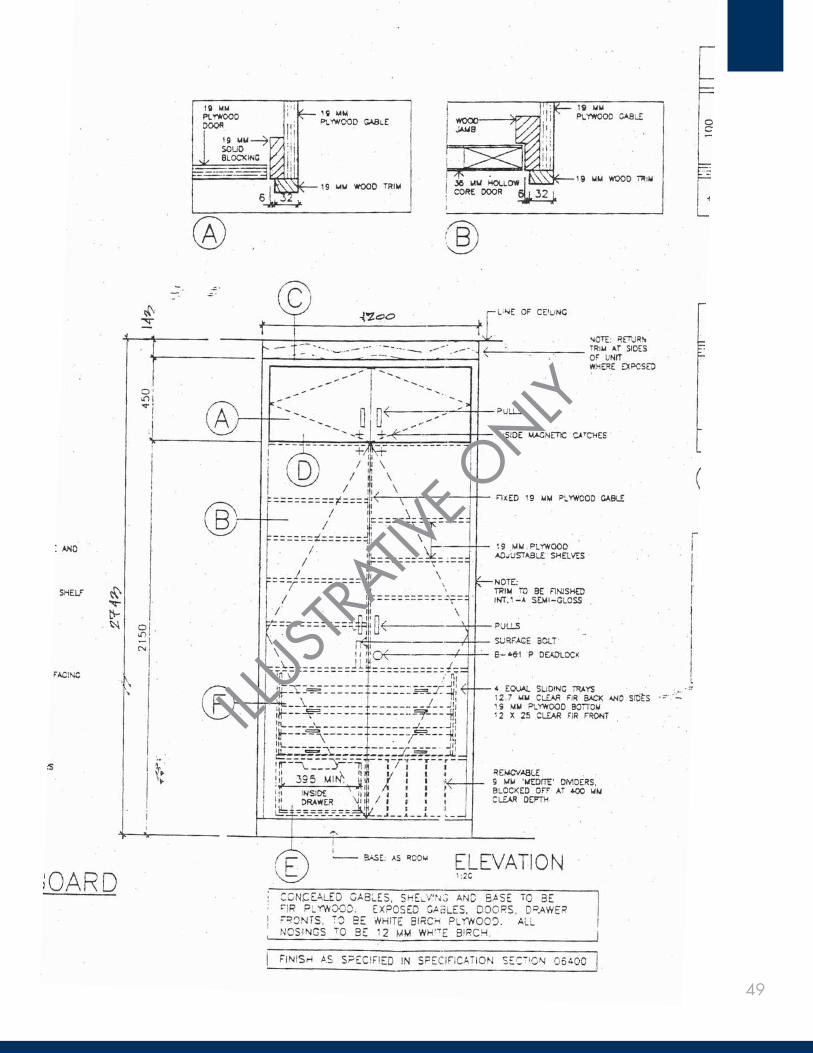
49
ILLUST
RATIV
E ONLY

50 MODULAR CLASSROOMS | DESIGN STANDARDS AND PERFORMANCE SPECIFICATIONS
ILLUST
RATIV
E ONLY

51
BLANK FOR PAGINATION


