The command bus transmitsinformation to each of theappliances.
movable shutters,shutters, blindsventilation
Electrical installation with a command bus
heating lighting
remote controlpush buttonswitch
Bus
wind strength temperature
Hager has many years experience developing andinstalling products based on Bustechnology.Tebis TS brings the followingbenefits : integrate within one system
services and functions whichpreviously worked independently from each other;
make modifications easier ;
make the electrical installationmore reliable, reducing thechance of electrocution;
tailoring the switch commandsto ensure greater user comfort
To obtain these benefits meansinstalling two separate circuits, asupply circuit to distribute energy and the control circuit tocarry information and instructions.
The advantages of the two distinct circuits are many :
The supply cabling is simplified
The only devices cabled on theLV (240V ac) side are the loadswhich need power (lights,garage doors...)
The controls for these loads (by push switches, thermostats. )are connected to the bus circuit.
Grouping of instructionsOne order (from a push-button.. )can control a set of lights orother loads or both at once (ascenario).
FlexibilityBy controlling loads using TebisTS, the electrical installation canbe modified and the use or con-figuration of the buildingchanged, without touching theLV wiring.
Electrical installation with bustechnology:
A developing concept After proving itself in industrialapplications, this installationconcept is spreading to includedomestic and commercialpremises.
A concept with accumulatingadvantages adapts easily to the
requirements of current andfuture occupants
gives greater conceptualfreedom to the architect
easy to install for theelectrician Tebis TS is based on simple
principles: the input devices react to
orders, controls and measures. They act on anON/OFF order from a switch,measure the variation ofambient temperature or oflight level, and transmitorders onto the bus.
the output devices receiveall information and orderstravelling on the bus andexecute orders which areaddressed to them.
the installation Bus is thetwisted-pair cable whichserves as the informationnetwork.
Remote ControlsRemote control receivers (radioor infrared) can be placed anywhere on the bus. Any loadin the installation can then becontrolled by remote control
When Tebis TS is used. thedegree of automation is nolonger limited by the complexityof cabling: new benefits can beoffered, which were previouslyimpractical...
230/400 V
the power circuitthe control bus
EDF
160
Tebis TS - a system for residential & commercial applications
161
A small number of productsfor many applicationsThe Tebis TS system uses only 3types of products:
Input devices,for transmitting to the outputdevices the orders from push-buttons or informationfrom thermostats or othersensors
Output devices,which control the electrical loads
System devices,for setting the relations betweeninputs and outputs, or forproviding the 29V supply
Tebis TS uses bus technologyfor the control of lighting, heating and roller-shutters andother similar loads, in both residential and commercialapplications.
Bus technology offers benefitsthat a traditional installationcannot provide.
Tebis TS is easy to install.Electrical contractors can continue to use familiar materialsand gain precious time in planning, then wiring, as there isonly one cable connecting eachpush button to the next. Rightup to - and after - completion ofwiring, any switch can be madeto control any load : the buildinguser can decide at the lastminute.
The Tebis TS system is particularly suitable for the home and for smallcommercial premises.
Benefits of choosing Tebis TS
Flexibility for the user: A single load can be controlled from several positions. Conversely, several loads can be con-trolled from a single point.
Update: The function ofeach switch can be changedat any time, without touchingthe wiring
Larger number of applications: Tebis TS workswith any brand of push-buttons and electricalload available
Safety : The control wiringvoltage is 29V, eliminatingthe danger of electrocutionfrom the control circuit.
Advanced lighting controlTebis TS enables the creation ofambient lighting as desired.Each push-button controls a setof lights or controls the dimmingof lights.
Flexibility in shutter controlShutters can be controlled individually, by group or alltogether. From push-buttons, oreven from a wind meter.
Heating at your commandFrom a heating regulator, TebisTS enables : setting in comfort or
economy mode.
override of heaters to frostsetting
override of heaters to ‘off’.
Grouped controls (ScenarioSwitching)In addition to the individual controls each Tebis TS productoffers, Tebis TS also allowssimultaneous control of severaldifferent loads (example : lighting& heating) from one push-buttonor sensor.
162
The configurator defines or modifiesthe electrical installation
A system easy to configure
Tebis TS: a system which iseasy to install All the control units are
linked to 2 bus wires viainput modules
All the electrical loads arelinked to the output modules
The allocation of linksbetween the push buttonsand the loads are carried outby means of an easy to usemodular device called a configurator
Some applications:the "leaving home" scenario.A single gesture is enough to: Turn out all the lights Lower all the shutters Reduce the heating Etc.
The scenario, which can bechanged at will, can be activatedwith a push button in the hall, atthe garage door or by radioremote control.
In a sports hallthe lighting must be adapted tothe activity taking place (tennis,volleyball, basketball, etc.) aswell as for the occasion(matches, training, preparation,etc).
To assist Specifiers andInstallers, Hager runcomplementary trainingsessions. Talk to yourHager representative for acurrent schedule ofseminars.
By assigning a push button toeach sport, it is possible toimplement the most suitablelighting for the sport being playedwith a single action, without theneed to operate several switcheswhich are each dedicated to apart of the playing area. The "projection" scenario
This makes it possible to move straight from a meeting sequence to aprojection sequence and vice-versa with a single command. As well asmanaging the lighting, this command can also drive the motorisedscreen and supply power to the projector.
Benefits that can be sold to the final user: Tebis TS offers the highest level of comfort possible Tebis TS ensures that inevitable future modifications can be
handled at least cost are are easy to do Tebis TS offers the most economical control of electricity Using remote controls to simplify your life Adding new push buttons without touching your decor Access all loads from anywhere
The configurator will make itpossible to define, for eachinput, which outputs are tobe commanded and in whichway (relay, dimmer, up,down, etc.)
After down loading this data tothe different products, theinstallation is functional.Changes or future developmentsto adapt the installation to theneeds of the client are achievedby simply reprogramming.
1/2. 1/2. training. matches
Tebis TS - examples of residential & commercial switching scenarios
163
Tebis TS - input modules
TS314
Inputs :- 2 or 4 volt-free contacts
Supply :- 29V bus (twisted pair)
Installation :fits behind standard wall wiringdevices (push-button or switch)in a wall box of minimum depth35mm. An insulated box is recommended
Description characteristics
Input devices send orders,received from push-buttons orsensors, to the Tebis TS outputdevices, via the twisted pair cable.
for technical details see pages 249-264.
input device flush-mountedfunctions :
- enables connection of volt free contacts (example : push-button)
- interprets orders and transmits them to the output devices to control lighting, shutters or other electrical loads.
- all the connections are for extra low voltage.
packqty.
No. of inputs
2
4
1
1
cat.ref.
TS302
TS304
Inputs :- 4 terminals rated at 230Vac
Supply :- 29V bus (twisted pair)
Installation :- DIN-rail
input devices, DIN-rail mounted
functions :- interprets orders at 230Vac
and transmits them to the output devices to control lighting, shutters or other electrical loads.
the TS314 and TS316 signalsthe state of the inputs when the29V twisted pair is switched on.Thus, it is well adapted to controllingautomatic devices (timers, telephone remote-control, solarcells, anemometers ...) It canalso be connected to push-buttons with indicatorlamps.
Note: TS310available to satisfy existing installations
2 1 TS314
Inputs :- 6 terminals rated at 230Vac
Supply :- 29V bus (twisted pair)
Installation :- DIN-rail
4 1 TS316
Description characteristics packqty.
size in 17.5 mm
cat.ref.
TS302
TS304
164
Tebis TS - input devices
TS322
description characteristics packqty
size in 17.5 mm
cat.ref.
Thermostat For control of convector heatersor underfloor heating
For control of conventional hotwater radiators
For electrical heating by convectors, radiator panel, radiating ceiling, etc...
1
1
1
TS320
TS321
TS322
Used in conjunction with theoutput device TS244.
functions: - local temperature level
adjustment.- manual selection of comfort,
reduced and frost settings on front face.
- remote setting via the bus of comfort, reduced and frost settings.
- indication of selected settingby 2 LED’s.
Outside temperature transmis-sion kit
Used in conjunction with temperature controllers TS320,TS321 and TS322 this kitenables regulation of heating,depending on the weather.
Supply : - twisted pair 29V- indication of the setting by 2LED’s
Installation :- surface-mounted, on a flush
wall box 60mm dia 50mm deep
Supply :- twisted pair 29V
14 TS330
key ring type:- 2 buttons, 2 inputs- with battery- attaches to key ring
4 buttons, 4 inputs- with battery- wall mounting bracket- a label for the function
of each button
8 buttons, 3 channels, 24 inputs- with battery- wall mounting bracket- a label for the function
of each button
1
1
1
remote control (RF) TU202
TU204
TU209
1
1
radio receiver (RF)
- receives orders from TU202,TU204, TU209 and transmitsthem to the bus.
supply :- 29Vdc Busmaximum of 4 inputs per receiver
supply :- 29Vdc Busmaximum of 12 inputs per receiver
TS350
TS351
TU 202
TS330
TU 204front
rear
TU 209front
rear
TS 350
TS 351
165
Tebis TS - output devices
Enable control of electricalloads, following orders frominput devices.There are 3 types of outputdevices :- for lighting- for small motor loads
e.g. shutters, curtains etc.- for heating
All output devices are providedwith LED indication of the output status and a manualoverride, on the front face. Theoutputs can be connected to different phases.
for technical details see pages 249-264.
description characteristics packqty.
size in 17.5 mm
cat.ref.
TS211
output devices for, ON/OFFswitching
For control of :- lighting- power outlets- any load controlled by a simple
contact
Functions :- on/off switching- on/off override- LED indication of each output
state
outputs :- 4 volt-free contacts 4A
AC1power supply :29Vdc bus
outputs :- 4 volt-free contacts 16A
AC1power supply : 29Vdc bus
outputs :- 6 volt-free contacts 4A
AC1power supply : 29Vdc bus
outputs :- 6 volt-free contacts 10A
AC1power supply : 29Vdc bus
outputs :- 6 volt-free contacts 16A
AC1power supply : 29Vdc bus
outputs :- 6 volt-free contacts 3 x 16A AC1 + 3 x 6A AC1power supply : 29Vdc bus
4
4
4
4
4
4
1
1
1
1
1
1
TS204A
TS204C
TS206A
TS206B
TS206C
TS206D
Output modules for dimmedlighting
Function :- ON/OFF switching- dimming- dimming scenarios
For :- 240V incandescent and
halogen lamps- ELV halogen lamps with
electronic or ferromagnetic transformers
For :- 240V incandescent and
halogen lamps- ELV halogen lamps with
electronic or ferromagnetic transformers
outputs :3, 1-10V outputs designed todrive:- EV102 and EV104 dimmers- transformers and electronic
ballasts with 1-10V control (inconjunction with volt free 16AAC1 contact)
power supply:- 240Vac 50Hz- 29Vdc Bus
outputs:- 1 direct output- 20 - 600W/VA (30oC)
20 - 500W/VA (40oC)240V/50Hz
power supply:- 29Vdc bus
outputs:- 1 direct output- 20 - 300W/VA (40oC)
240V/50Hzpower supply:- 29Vdc bus
6
4
4
1
1
1
TS211
TS210
TS210A
TS 210
TS204C
TS206B
166
Tebis TS - output devices
description characteristics pack qty
1
size in 17.5 mm
cat.ref.
Output modules for 4 slatblinds
Functions :- opening and closing by
pressing for an extended time (400ms)
- STOP by pressing briefly- manual override
UP/DOWN/STOP- LED indication of each output
state- wind safety function
outputs :- for 4 motors 240Vac (6A AC1)
supply :- 29Vdc Bus
4 TS224
14 output device, for heating
For control of :- underfloor heating- electric convectors- radiating panels- association with TS320, TS321
and Ts322 thermostats
Functions :- On/OFF control switching- On/OFF override on front face- LED indication of each output
state
outputs :- 4 volt-free contacts 16A AC1
supply :- 29Vdc Bus
4 TS244
14 way indicator panel
Functions :- reproduces on/off contact
status of associated output by LED indication
supply :- 29V twisted pair (bus)
installation :- surface mounted on a flush
wall box = 60mm dia 50mm deep
TS400
TS400
1telephone interface unit
application:by linking this product to a Tebisinput device, you can controlspecific Tebis system loadsremotely from a touch tonetelephone
functions:- 3 channel remote control
interface with voice guide- restricted access via 4 digit
user code- circuit status indicator light- manual override push button- on/off switching- timed off switching
(1-100hours)
outputs:3 volt free changeover contacts5A 250V AC1
supply:230V ac 50Hz
TS003
TS003
Output device for 4 movableblinds or canopy blinds
Functions :- operating and closing by
pressing briefly- STOP by pressing briefly- manual override
UP/DOWN/STOP- LED indication of each output
state- wind safety function
outputs :- for 4 motors 240Vac (6A AC1)
supply :- 29Vdc Bus
4 1 TS223
TS223
167
Tebis TS - system devices
description characteristics
Control device
Functions :- sets the relationships betweenthe input and output devices- displays the relations and thetype of control offered
supply :- 230Vac 50Hz- 29V twisted pair (bus)
packqty
size in 17.5 mm
16
cat.ref
TS100
Supply
Functions :- generates the 29V system
supply voltage- opens circuit in case of short-
circuit or overload
supply :- 230Vac 50Hzoutput :- 29Vdc extra low voltage- 640mA, resistant to short-
circuits - 128 Tebis products
17 TS110
supply :- 230Vac 50Hzoutput :- 29Vdc extra low voltage- 320mA, resistant to short-
circuits - 64 Tebis products
14 TS111
Twisted pair bus cable
EIB-Y (ST) Y x 2 x 2 x 0.8mm(test voltage 4kV)
For wiring of the control cabling.
100m long 1 TG018
500m long 1 TG019
Connectors for twisted pairtermination (pack = 50 pieces)
- consists of an anemometer and electronic control unit.
TG050supply :- 230Vac 50Hz
detection level :- adjustable from 5 to 55km/h
(factory-adjusted at 25km/h)
TS100
TS111
TS110
TG008
TG050 Note: used in conjunction with a Tebis TS310 input device
249
Tebis TS - description of the system
Input productsRegister the information coming from the control units (push button,switch, timer, etc). These orders are then carried via the bus cable tothe output modules.
Output products Interpret the information transmitted by the input products, convertthem into action and power the connected loads. The outputproducts are divided into three large families: lighting, shutters/blindsand heating.
System productsThey are of two types:
- The power supply supplies the 29 V dc to power the bus.
- The configurator connects the input and output modules. In other words, it enables the operation of the installation.
Operating principle The Tebis TS installation differs from the traditional installation in thatit separates control and power.
The power circuit comprises the protection and the power supply tothe electrical loads by means of the output modules. The controlcircuit (bus) joins all the input products and sends orders to theappropriate output contacts.
N Ph
PB1
PB2
PB3
PB4
4inputs
1 3 13 15 17 19
autoTS 100
prog.
0...9...
reset
CL
OK+
11
3 4
1 2
1 3 11 13 17 19
12 14 18 20
3 4
1 2
1 3 11 13 17 19
12 14 18 20
3 4
1 2
1 3 11 13 17 19
12 14 18 20
15
16
TS 320
I > I max
ON
reset
reset
29 V
6T0090 a
TS 110
L N 230 V ~
BUS 29 V
230 V50/60 Hz
L N
TS 350
1
2
1 2
43
65
87A
B
C
1 2
43
Tebis TS is a new installation system providing enhancedfunctionality for controlling lighting, shutters and heating.
Tebis TS offers simple solutions for complex and changing needs.The more demanding the user, the more evident the benefits. In atraditional installation, the functions are fixed once the cabling isfinished. In the simplest installations, loads are directly connected tothe control devices. As the users become more demanding, theirneeds change. Central or grouped controls are required, cabling andlabour increase rapidly.
The method of wiring a Tebis TS installation is always identical,independent of the functions needed, which reduces the time forplanning and installation. Thus, with Tebis TS, any push button can deliver any command (on,off, up/down variation, as an individual, group, master or scenariocommand) to any installation load.These new possibilities simplify life for current and future occupantsby freeing them from certain tasks while guaranteeing that theelectrical installation has a high level of adaptation and developmentpotential.
How is a Tebis TS installation structured?
Entry products are attached to control units. System products provide the 29Vbus supply and allow theinstallation to be configured.
Output products supply power tothe loads.
distribution board
supply
Bus EIB 29 V ...
configurator(programmer)
7 9 13 15
8 10 14 16
TBTS
4 output module
S3
S1
S4
S2E1
E2
E3
E44 inputmodule
Ph N
Bus 2 wire 29 V
Electrical connection
The control circuit (bus) joins all the input modules together to whichthe control units and the output modules are attached. After wiring,simply program the installation according to the desired operation.
250
Tebis TS - how the system works
Configuration principleConfiguration is concerned with associating each input with theoutputs which are to be controlled as well as with the type of control.In other words, specifying the required action (on/off command,dimmer, up/down, etc.).The choice of "type of control" is carried out directly on theconfigurator matrix. Using easily understandable symbols, theelectrician can choose the essential functions in the three fields ofapplication.Whatever the functions may be, which are to be carried out, theconfiguration principle remains identical and is based on the creationof configuration links.A configuration link connects an input to "n" outputs ( n >1) bycarrying a "type of control".
Operation principle
autoTS 100
prog.
0...9...
CL
OK+
lighting
heating
shutters
selection keys for “type ofcommand”
Creation of a configuration link
+-
auto
prog.
0...9...
1/10 V
STOP
OK
1 link = selection ofan input no.
selection ofoutputs
selection of acontrol type
+ + + ok
The inputs and the types of control are selected on the configurator.The outputs are designated by the keys of the modules concerned.
ConfigurationIs carried out at the end of the construction with the help of the TS100 configurator. The TS 100 module is the only necessaryprogramming tool required to carry out all the logical links whichdefine the function of the installation.The configuration takes place in 3 successive stages.The mode selector of the configurator allows the passage from onestage to the other.
1. Numbering of the inputsThis operation gives a unique number to identify each inputconnected to the installation. Done by simply closing the inputcontacts once whilst in numbering mode
2. Programming the linksThis involves creating all the configuration links (see the principle).
TS 320
TS 210
. . . . .
. . . . .
. . . . .
. . . . .
1 3 13 15 17 19
autoTS 100
prog.
0...9...
reset
CL
OK+
11
I > I max
ON
reset
reset
29 V
6T0090 a
TS 110
L N 230 V M
BUS 29 V
230 V50/60 Hz
L N
TS 350
12
43
PBPB
PBPB
PBPB
2520
510
15 30
°C
240 VM
240V contactinputs
luminous buttonsor switches240 V
movement detector
wind gauge 240 V
twilightswitch
240 V AC
standardbuttonsand switches
window anddoor contacts
radio remotecontrol
temperatureregulator
thermostat
TS 320
TS 304
TS 302
TS 350TU 204
29 V DC
TS 316
timer switch240V inputmodule
bus supply module
configurator module
heatingoutputs
movable shutteroutputs
dimmedoutputs
lightingoutputs
controlled load
TS 244
inputs
2INPUTS
4inputs
2inputs
outputs
auto
prog.0...9...
The steps
- auto downloading
- established links
- prog. programming of the links
- 0… 9… numbering of the inputs3. Downloading of the programWhen the selector is moved to Auto mode, the programming data istransferred to the different input and output products in theinstallation.
After downloading, the installation is operational. All the informationis decentralised to each product. Each module is autonomous. Theconfigurator simply facilitates subsequent program changes.
The Tebis TS system
OK
251
Tebis TS - system description
+
+
Tebis TS has been further enriched with version 8.2. The followingfunctions are now available on any outputs: - Priority commands (override), represented by the symbol “P” on
the display- Adjustable delay times from 1 sec to 12 hr represented by the
symbol “t” on the display
- Dimming scenarios allow preset lighting levels to be called uponat the push of a button (dimmed loads only). Symbol “S”
The new functions are available on the configurator's display. Pressthe desired control function ( , ) button for more than 3 secondsand the new functions appear.
applications control units functions input products output products
lighting on, off, on/off, dimmingdelay time on or offscenario
The above functions can be integrated into the individual, group,master or scenario controls: - The individual (local) control corresponds to : one or more inputs
controlling a single output- The group (zone) control corresponds to : one or more inputs
controlling a group of outputs
- The master control corresponds to : one or more inputscontrolling all the outputs
- The scenario function: this is a multi-action command which canact simultaneously on lighting, shutters and heating .
symbol on TS 100 type of control input connected to
ONA press of the button or closing of the contact always switches theassigned outputs ON
ON/OFFClosing of the contact switches the assigned outputs ON. Openingof the contact switches the assigned outputs OFF
Switch contacts(switch clock, twilight switch...)
ON/OFF (remote switch control)Each press of button changes the assigned output status ON/OFF ,Assigned output is ON with one press of the button,OFF with next etc
Tebis TS : Overview of the types of control - lighting and small power
Priority ONClosing the contact switches the assigned outputs ON (remain ONwhilst switch is closed). Opening contact assigns: OFF with inversionmode, remains ON if the hold mode is selected
Switch contacts(switch clock, twilight switch...)
Priority OFFClosing the contact switches assigned outputs OFF (remain OFFwhilst switch is closed). Opening contact assigns: ON with inversionmode, remains OFF if the hold mode is selected
Switch contacts(switch clock, twilight switch...)
Timer ONA pressed button or closed contact always switches assigned outputON for time delay (1s to 12h) outputs switch OFF at end of time delay
Tebis TS : Overview of the types of control - Venetian blind or roller-shutter control
symbols on TS 100 type of control input connected to
UPA longer press of the push button or closing contact commands UP. Continuesto the upper stop position until stopped. Short press stops movement. Afterstopping every short press adjusts the blade angle.
Push ButtonSwitch control (switch clock, twilightswitch, wind sensor...)
DOWNA longer press of the push button or closing contact commands DOWN.Continues to the lower stop position until stopped. Short press stops movement.After stopping every short press adjusts the blade angle.
Push ButtonSwitch control (switch clock, twilightswitch, wind sensor...)
UP/DOWNClosing contact commands DOWN (close). Open contact commands UP (open).Command will continue to stop position. Stopping movement is only possiblethrough separate push buttons controlling UP or DOWN.
Switch contacts(switch clock, twilight switch...)
Wind Safety*Closing of the anemometer’s contact commands UP to the upper stopposition (security position). All controls are ignored until anemometer’scontact opens
Wind strength set TG 050
Priority UPClosing contacts commands UP. Remains UP whilst switch is closed.Opening contacts commands: DOWN in inversion mode, remains UP if holdmode is selected
Switch
Priority DOWNClosing contacts commands DOWN. Remains DOWN whilst switch isclosed. Opening contacts commands: UP in inversion mode, remains DOWNif hold mode is selected
Switch
TimerPress button or close contact commands UP to upper stop position. Presettime delay commands DOWN to stop position
Switch
symbols on TS 100 type of control input connected to
Day temperatureA press of the button or closing of the contact activates the day temperature
Switch contacts(switch clock, buttons)
Drop temperatureA press of the button or closing of the contact activates the drop temperature
Switch contacts(switch clock, buttons)
Day/Drop*Temperature regulator: Short press of button for day/drop. Switch contact:closing contact activates day temperature, opening contact activates droptemperature
Temperature regulatorSwitch contact (switch clock..)
Frost protection*Temperature regulator: Long press for frost protection. Next press returns tocurrently applicable state. Switch contact: closing contact activates frostprotection. Opening contact returns to currently selected state
Temperature regulatorSwitch contact (window contact,switch clock...)
Priority Drop TemperatureClosing contact activates drop temperature and remains while switch isclosed. Opening contact: changes to day if inversion mode is selected,remains to drop temperature if hold mode is selected
Switch contacts (switch clock, twilight switch..)
Tebis TS : Overview of the types of control - individual room temperature regulation
STOP
* The configuration unit TS100 only allows one relationship with those type of control
STOP*Closing contact stops the heating, opening the contact re-activates thecurrently selected day, drop or frost protection temperature.This function has priority over the day, drop or frost protection temperature.
Switch contacts(switch clock, twilight switch...)
Priority Day TemperatureClosing contact activates day temperature and remains while switch isclosed. Opening contact: changes to drop if inversion mode is selected,remains to day temperature if hold mode is selected
Switch contacts(switch clock, twilight switch..)
Timer Day TemperaturePress button or close contacts activates the day temperature during a timedelay 1s to 12h. After time delay drop temperature is activated
Timer Drop TemperaturePress button or close contacts activates the drop temperature during a timedelay 1s to 12h. After time delay day temperature is activated
The scenario function The scenario function is a multi-action, multi-application command.It enables up to 13 different commands to be associated with anyinput in the system.Example: in the evening it is dark and you are leaving your home. Bypressing the PB at the front door, the garage door and/or the radioremote control, with one gesture you will be able to:
- Turn on the exterior lights on a timer- Turn off all the lights in the house- Turn on a controlled socket outlet to simulate your presence (radio
and light)- Lower all the shutters- Switch all the heating to the minimum mode
3 4
1 2
1 3 11 13 17 19
12 14 18 20
3 4
1 2
1 3 11 13 17 19
12 14 18 20
15
16
Bus
3 4
1 2
1 3 11 13 17 19
12 14 18 20
TS 200
TS 220
TS 240
PB PB
PB PB
3 31 2
1 3 11 13 17 19
12 14 18 2010
15
16
9
TS 211
- group turning out of lights first floor- time delay OFF "x" circuit
- lighting ground floor- time delay ON "y" circuit
- lowering shutters first floor
- raising shutters ground floor
1 2
3 4
Any input in the systemcan transmit function scenario
12
124
36
58
7ABC
124
3
TS 350
TS 304
4input
- scenario level 1 group 1- scenario level 2 group 2- scenario level 3 group 3
- comfort zone 1- comfort restart 4 hours zone 2
- minimum zone 3- minimum restart 8 hours zone 4
between 2 and 13 different commands
types of commands available
Advantages and application situationsThe scenario function frees the user from small daily constraintseach time s/he is obliged to carry out multiple and repetitive tasks.This is particularly the case for all small businesses. In the morningand evening it is necessary to operate the metal shutters, the lightingfor the shop, the shop window, the storeroom and the shop sign, thepower supply for the cash register, video cameras, etc.These successive operations can be replaced by a single command,thus eliminating any oversights.In a Tebis TS installation, the scenario function can be allocated toany one of the system's inputs, including remote control. It enablesthe number of control points to be reduced and simplifies repetitiveprocedures; this increases the level of comfort for the user.
The diversity of activities in the service sector enables each user toimagine situations in his professional environment where he is calledon to start up different technical equipment once or several times aday.Examples in multi-purpose rooms: 1 PB per practical activity,occupancy scenario (non-occupancy of hotel room), projectionscenario in a meeting room or classroom.
Configuration 20 scenario functions are available per installation. The scenariofunctions exploit the "types of controls" corresponding to the firsttwo columns in the configurator's matrix.To program a scenario, you only need to ok the first configurationlink by holding down the OK key > 2 secs. In these conditions theinput number does not increment; this enables the association ofseveral links to the one input. The final link of the scenario isrecorded by pressing the key normally.
3 4
1 2
1 3 11 13 17 19
12 14 18 20
3 4
1 2
1 3 13 17
14 18
15
16
BP3 4
1 2
1 3 11 13 17 19
12 14 18 20
15
16
. . . . .
. . . . .
. . . . .
turning out all the lights
lowering all the shutters
heating switches moved tominimum mode
TS 302 / TS 304
"Leaving" scenario
PB
254
Tebis TS - technical data
Tebis TS : technical dataMaximum number of products per installation- 64 products with a TS111 power supply- up to 128 products with a TS110 power supplyMax. 300 input numbersTotal bus width : 1000m max. Max. distance between the power supply and the TS products:350m.
700 m
350 m 350 m
TS100
TS304 TS204
TS204 TS204
TS304TS204 TS110
Bus power supply
Recommendations for implementing a TS installation 1. Install the TS products in the base of the cabinet to avoid an
excessively high operating temperature.2. Connect all the input/output products to the 29 V bus.3. Connect the electrical cables to the different outputs in the output
modules.4. Follow the configuration instructions for the system.
Structure of the bus wiringIt can be star-shaped, linear, tree or ring-shaped.
The EIB Y (ST) Y 2 x 2 x 0.8 (ref. TG 018, TG019) bus cable can belaid within immediate proximity of the low voltage network. However,you are advised to make provision for wall boxes which are separateor fitted with separating partitions for the bus cable connections andthe LV cable connections. The EIB cable is insulated to 4 kV.(NFC 3209)
Command information modulated symmetrically, superimposed onthe system voltage of 29 V - (VLV), transmission of serial asynchronicdata (time-division multiplex), CSMA/ CA access process,transmission speed 9600 BPS.
Immunity to interference in accordance with IEC and EIBA standards.
Joints in the bus cableWhere joints in the bus cable are required, we recommend (in orderto minimise any conductor damage) the use of the EIB screwlessterminal TG008 within a suitable junction box.
255
Tebis TS - Radio remote control
Technical characteristicsRemote control TU 202- Transmission frequency: 433 MHz
- Transmission security: open - ended / encoding and encryption
- Keys: 2 keys - numbered 1 and 2
- Range in a free field: 50m
- Power supply: 3V CR 1620 lithium cell power
- Degree of protection: IP30
- Operating temperature: -20°c to +70°C
- Storage temperature: -20°C to +70°C
- Dimensions: 61 x 29 x 16
- Weight :25 9
- Key ring chain
- Comply with EN 300 220-1
- LED to indicate radio transmission
Remote control TU 204- Transmission frequency :433 MHz
- Transmission security: open - ended / encoding and encryption
- Keys: 4 keys - numbered 1 to 4
- Range in a free field: 100m
- Power supply: 3V CR 1620 lithium cell power
- Degree of protection: IP30
- Operating temperature: -20°c to +70°C
- Storage temperature: -20°C to +70°C
- Dimensions: 111 x 51 x 18
- Weight: 60 9
- Supplied with wall-mounting bracket
- Comply with EN 300 220-1
- LED to indicate radio transmission
Remote control TU 209- Transmission frequency :433 MHz
- Transmission security: open - ended / encoding and encryption
- Keys: 8 keys - numbered 1 to 8
1 group selection key
- Range in a free field: 100m
- Power supply: 3V CR 1620 lithium cell power
- Degree of protection: IP30
- Operating temperature: -20°c to +70°C
- Storage temperature: -20°C to +70°C
- Dimensions: 111 x 51 x 18
- Weight: 70 9
- Supplied with wall-mounting bracket
- Comply with EN 300 220-1
- LED to indicate radio transmission
Remote control TS 350- Transmission frequency: 433 MHz
- Transmission security: open - ended / encoding and encryption
- Keys: 4 keys - numbered 1 to 4
- Degree of protection: IP54
- Operating temperature: 0°c to +70°C
- Storage temperature: -20°C to +70°C
- Dimensions: 130 x 80 x 35
- Dimension of antenna: 110mm
- Comply with EN 300 220-1
- LED to indicate radio transmission
- wall mounted with 4 screws
1
2
1 2
43
1 2
43
65
87A
B
C
Bus
TS 350
12
1
24
3
6
5
8
7A
BC
1
24
3
TU 2
09
TU 2
04
TU 2
02
LED to indicate radio transmission
LED to indicate radio transmission
LEDs to indicate radio transmissionand to visualise the group
256
Tebis TS - input devices
Input modules TS302 / TS303 /TS304
FunctionUp to 2 conventional push buttons or switches or other voltage freecontacts can be connected with the push button input TS302.
The TS303 is an input device with 2 inputs with period transmitting.The status of the inputs are transmitted automatically every 15 minutes as well as after each change of status of one of theinputs.
The product dedicated to heating is particularly suited to manage traditional automation products like thermostats, program-mable thermostats regulations. During configuration, it can only beconnected to the outputs of the TS240 device.
Up to 4 conventional push buttons or switches or other voltage freecontacts can be connected with the push button input TS304
These devices are fitted into a flush box - e.g. behind a connectedswitch.
These devices transfer the operation information and control the allocated outputs over the bus system.
Technical specificationsVoltageSupplyproduct supply via the EIB Bus
Environment- working temperature: 0 to +45ºC- storage temperature: -20 to +70ºC- ingress protection IP: IP 20
Connection- connection to the Bus by red/black plugable TG008 terminal- connection of the inputs by plugable connector, the connecting - cable connector / device is supplied with the product.It includes:- the plugable connector- csa conductor 0.22mm2 - length: 200mm
Electrical characteristics- supply voltage: 230V~ 50Hz system voltage 29V- connectable type of contacts: push-buttons and switches- inquiry voltage 5V is generated by the device- contact current: 0.5mA
Operation characteristics- min. closing time: 50ms- length of cable extendible up to 5m by twisted pair wire
Dimensionssize; 38 x 35 x 12mm
+-Systemvoltage29 V DC (SELV)
TS 303599303 1 E1 E2
- +
t°
Test / adressing button
indication of function
conventional push-button or switch
(the black/white connection wires have the same reference potential)
Bus presence test
yello
wre
d
+-Systemvoltage29 V DC (SELV)
- +
E1 E2 E3 E4TS 304599304 1
Systemvoltage29 V DC (SELV)
Test / adressing buttonindication of function
conventional push-button or switch
(the black/white connection wires have the same reference potential)
Bus presence test
yello
w
red
vert
ble
u
+-
TS 302599302 1 E1 E2
- +
Systemvoltage29 V DC (SELV)
Test / adressing button
indication of function
conventional push-button or switch
(the black/white connection wires have the same reference potential)
Bus presence test
yello
wre
d
Layout TS302
Layout TS304
Layout TS303
Note: for the connection of one push button, isolate all unused wires
Note: for the connection of one push button, isolate all unused wires
Note: for the connection of one push button, isolate all unused wires
257
Tebis TS - input devices
6 inputs module TS 310FunctionThe input device TS 310 provides 6 inputs for 230V AC for the connection with time lag switches, air speed indicator, light sensitiveswitches or other 230V contacts.
System voltage:Bus 29 V and 230 V~ /50 Hz
Environment- Working temperature: 0ºC to +45ºC- Storage temperature: -20ºC to +70ºC- Ingress of protection IP: IP 40
Connection - connection to the Bus via the TG 008 plugable terminal - connection of the 230V supply contacts on the entries by cage
terminals - cage terminals: flexible: 1mm2 to 6mm2
rigid: 1,5mm2 to 10mm2
Characteristics of an entry - Un: 230V~ - 15% 50/ 60Hz (open contact ), entries can be
connected on different phases, - In: 1 mA (closed contact) - levels for entries E1 to E3:
0...30V~ = 0 80 ... 230 V~ = 1 - levels for entries E4 to E6 and for the detection entry:
a0 ... 130 V~ = 0 80 ... 230 V~ = 1 - maximum length between probe and entry: 100 m
( connection of push-buttons on the entries E4, E5, E6: up to 10 push buttons with indication light in parallel ( 1 mA per neon lamp ).
Electrical connection
Note: the inputs can be connected to different phases. In case of power failure: the entries connected on the same phase as the supply phase of the device will not be affected by the power failure (no unwished instructions are sent). The initial status of the entries are systematically resent after the power failure.
1 11 15 19
12 16 20
1 2 3
4 5 6
2
Systemvoltage29 V DC (SELV)
Ph
N
selection switch: up : normal function or programming down : manual handling with push-buttons
operating push button: a) programming b) monual operation
indication of switch state
watched phase
inp
ut 1
inp
ut 2
inp
ut 3
inp
ut 4
inp
ut 5
inp
ut 6
illuminated push button
further bus connection
auto
Ambient temperature controller TS 320, TS 321 et TS 322Function In association 4 output modules TS 240, these controllersregulate the heating of either electric heaters or hot water radiatorsequipped with electro-thermal actuators mounted directly on theradiator or on the hot water boilers. The TS 240 and the controllers communicate with one another viathe bus 29V. The controllers must be chosen according to the heater types. Theselection of the settings comfort ECO or frost protection can be done either remotely over the bus or locally by push-buttons on the controllers - soft press: switching from comfort to ECO or vice versa - hardpress (2 sec.): switching to frost protection (reset by soft press). Thepush-button on the front allows numbering the controller while programming with configurator TS 100;
Supply voltage:Bus 29 V
Functional characteristicsPl regulation with integral time actionTime basis: - TS 320: 20 min
adjusting range of the potentiometer: 0ºC to ± 45ºCregulation class: Class B
Environment- Ingress of protection IP: IP 302- Working temperature: 0°C to + 45 °C- Storage temperature: -20°C to +70 °C
Product presentation
= comfort
= ECO
= Anti-frost
➀ selection push-button ➁ potentiometer ±4°C➂ actual setting
Electrical connection
seal the sheath
hagertebis
60
connection
flush mounting box: ø 60mm; fixing by screws
81
81
2
3
1
258
Tebis TS - outside temperature transmitting kit
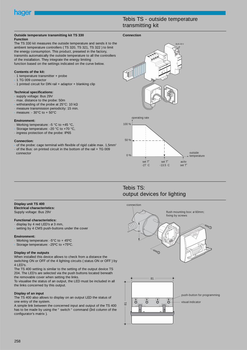
Outside temperature transmitting kit TS 330FunctionThe TS 330 kit measures the outside temperature and sends it to theambient temperature controllers ( TS 320, TS 321, TS 322 ) to limitthe energy consumption. This product, preseted in the factory, transmits automatically the outside temperature to all the controllersof the installation. They integrate the energy limiting function based on the settings indicated on the curve below.
Contents of the kit:- 1 temperature transmitter + probe- 1 TG 009 connector- 1 printed circuit for DIN rail + adaptor + blanking clip
Technical specifications:- supply voltage: Bus 29V- max. distance to the probe: 50m- withstanding of the probe at 25°C: 10 kΩ- measure transmission periodicity: 15 min.- measure: - 30°C to + 50°C
Environment:- Working temperature: -5 °C to +45 °C,- Storage temperature: -20 °C to +70 °C,- ingress protection of the probe: IP65
Connection:- of the probe: cage terminal with flexible of rigid cable max. 1,5mm2
- of the Bus: on printed circuit in the bottom of the rail + TG 009 connector
Connection
100 %
outside temperature
operating rate
50 %
0 %
set T˚-27 C
activset T˚
set T˚-13.5 C
TG 009
587009 4
TS 330
599330 4
BUS 29 V
6 8
Tebis TS:output devices for lighting
Display unit TS 400Electrical characteristics:Supply voltage: Bus 29V
Functional characteristics:- display by 4 red LED’s ø 3 mm,- setting by 4 CMS push-buttons under the cover
Environment: - Working temperature: -5°C to + 45ºC- Storage temperature: -25ºC to +75ºC.
Display of the outputs When installed this device allows to check from a distance theswitching ON or OFF of the 4 lighting circuits ( status ON or OFF ) by4 LED’s. The TS 400 setting is similar to the setting of the output device TS204. The LED’s are selected via the push buttons located beneaththe removable cover when setting the links. To visualise the status of an output, the LED must be included in allthe links concerned by this output.
Display of an input The TS 400 also allows to display on an output LED the status ofone entry of the system. A simple link between the concerned input and output of the TS 400has to be made by using the “ switch “ command (3rd column of theconfigurator’s matrix ).
81
81
push-button for programming
visual indicator
hagertebis
60
connection
flush mounting box: ø 60mm; fixing by screws
259
Tebis TS - output devices for lighting
Output devices for lighting TS 204 or TS 206FunctionThe output devices TS 204 or TS 206 allow:- “ ON “ / “ OFF “ switching- temporary “ ON “ or “ OFF “ from 1 second to 12 hours- “ ON “ or “ OFF “ overrides
These devices are controlled over the system line by allocated businputs. They also provide a manual override facility and a visual indi-cator ON/ OFF
Working temperature 0 to +45°C 0 to +45°C 0 to +45°C 0 to +45°C 0 to +45°C
Storage temperature 0 to +45°C 0 to +45°C 0 to +45°C 0 to +45°C 0 to +45°C
Dimensions 4 4 4 4 4
Connection: flexible 1 to 6mm2 1 to 6mm2 1 to 6mm2 1 to 6mm2 1 to 6mm2
rigid 1.5 to 10mm2 1.5 to 10mm2 1.5 to 10mm2 1.5 to 10mm2 1.5 to 10mm2
ConnectionTS204A and TS204C TS206A, TS206B and TS206C
TS 206auto
1 3 7 9 13 15
8 10 14
5 11
6 12 16
1 2 3
4 5 6
Systemvoltage29 V DC (SELV)
output 1 output 2 output 3
output 4 output 5 output 6
indication of switch state
operating push-button for manual operation
PhN
selection switch Auto / Manu
test / adressing button
Systemvoltage29 V DC (SELV)
TS 204auto
1 3 7 9 13 15
8 10 14
5 11
6 12 16
output 1 output 2
output 3 output 4
indicaion of switch state
operating push-button for manual operationtest /
adressing button
selection switch Auto / Manu
NPh
260
Tebis TS - output devices for lighting
Dimming output devices TS 210 and TS210A direct output,TS211 3 outputs 1-10VThe TS 210 and TS 211 are piloted via push-buttons connected tothe input devices. One single push-button can pilot a dimming circuit: - short pushes will switch “ ON “ and “ OFF “ - long pushes will increase or decrease the lighting level An “ ON “ order will bring back the luminosity to the initial level.
Technical characteristics
references TS 210 and TS210A TS 211
number of outputs 1 direct output protected against overloads 2 outputs (per output : 1 contact TOR+1 - 10V)
contact rating 600 W (see chart below) TS210 contact TOR 16A AC1 250 Vsame characteristics as TS200)
300W TS210A output 1 - 10V : max. current 50mA
supply voltage Bus + 230V 50Hz Bus + 230V 50Hz
consumption 0.5VA 5VA
power dissipation < 5 W 10 W
working temperature 0 to +45 °C 0 to +45 °C
storage temperature -20 to + 70 °C -20 to + 70 °C
dimensions 4 6
connection: flexible 1 to 6mm2 1 to 6mm2
rigid 1.5 to 10mm2 1.5 to 10mm2
Note: before using the TS 210, it has to be configured by specifying the load to be controlled.
Technical characteristics of load contacts TS 210
Working temperature35 °C 45 °C
Type of load mini load maxi load
incandescent 20 W 600 W 500 W
VL halogen 20 W 600 W 500 W
Hal. VLV + transfo 20VA transfo 600VA transfo 500VAconvention. transfor. Load 15 W load 480 W load 400 W
Hal. VLV + electronic transfo 25VA transfo 600VA transfo 500VAtransformer load 20 W load 540 W load 450 W
ConnectionTS210
TS211 + dimmer
load
1 3
14 16
load
Systemvoltage29 V DC (SELV)
Push-button for configurat of load type (load select)
TS 210 auto
Ph
N
selection switch Auto / Manu
load type indication
Adressing button
indication of overload or overheating: - switched on for overheating - flashing for overload or short-circuitoperating push-button for manual operation
1 3 5 7 9 11
2 4 6 8 10 12
EV 103
auto
31 2
PhN
1 3 9 11 13 15 17 19
10 12 14 16 18 20
- + - + - +
Systemvoltage29 V DC (SELV) load
TS 211
TS 211 + electronic ballast
auto
31 2
PhN
1 3 9 11 13 15 17 19
10 12 14 16 18 20
L N
-+
- + - + - +
1-10 V
TS 211
Systemvoltage29 V DC (SELV)
further busconnection
further busconnection
electronic ballastsfluorescent tubeindication of switchstateoperatingpush-button for manuoperation
commut.Auto /Manu
EV101EV103
cd1 cd2 cd 3
cd1 cd2 cd 3
output 1 output 2 output 3
output 1 output 2 output 3
261
Tebis TS - output devices for blinds and shutters
output for 4 blinds, shutters TS 223, TS 224, The range of products blinds and shutters covers two applications: - the unit TS 223 manage the orders rise, coming down, and stop.
They will pilot rolling shutters, blinds. - the units TS 224 manage the orders rise, coming down, stop as
well as tilting blinds. They will pilot blinds.
In “ Auto “ mode the commands are supplied from the input devicesof the Tebis system (TS304 or TS310).
In the “ Manual “ mode, the commands are supplied locally from thepush-buttons on the front of the device ( override ).
Technical characteristics
References TS 223, TS 224
number of output 4
contact rating 6 A AC1 250 V ~
electrical endurance 100 000 operations
alimentation Bus
consumption < 0 2 W
power dissipation < 1 W
working temperature 0 to +45 °C
storage temperature -20 to +70 °C
dimensions 4
Connection: flexible 1 to6mm2
rigid 1.5 to 10mm2
ConnectionTS223 / TS224
3 4
1 2
1 3 5 7 9 11 13 15
6 8 10 12 14 16
Systemvoltage29 V DC (SELV)
selection switch Auto/Manu
load type indication
adressing button
indication of switch stateoperating push-button for a) programming b) manual operation - 1 push :down- 2 push :stop- 3 push :up- 4 push :stop- 5 push : down
Ph
N
262
Tebis TS - output devices for heating
Output device for heating TS 244
The output device TS 244 will carry out the “ ON “, “ OFF “ instructions given by: - the temperature controllers TS 320, TS 321 or TS 322 - traditional temperature controllers connected to the periodical
pulsed entry module TS 303
The “ Manu “ mode allows the override of the different outputs. After 1 hour, in case of defect or absence of controllers, the TS 240will ensure a no frost protection ( 1 minute “ ON “ - 4 minutes “ OFF “ ). The indication light of the output related to this protectionis flashing.
Technical characteristics
reference TS 244
number of output contacts 4 voltage free contacts
contact rating 16 A AC1 250 V
electrical endurance 20 000 operations
supply voltage 29V
consumption 5 VA
power dissipation <8 W
working temperature 0 °C to +45 °C
storage temperature -20 °C to f70 °C
dimensions 4 mod
connection: flexible 1 to 6mm2
rigid 1,5 to 10mm2
Connections
TS 244
3 4
1 2
L L
L L
7 9 13 15
8 10 14 16
auto
Systemvoltage29 V DC (SELV)
Bus
Bus
Bus
Bus
263
Tebis TS - system devices
Configuration unit TS 100The configuration unit TS 100 defines the allocation and functionsbetween the Tebis TS inputs and outputs ( for example TS 304 andTS 206 ).
Electrical characteristics:- supply voltage: 230 V~ 50 Hz, Bus 29 V, - power consumption: 7 VA, - power dissipation: 7 W. Operating data contact rating indicator output: 1 A 250 V~ Environment: - working temperature: 0 °C to +45 °C, - storage temperature: -20 °C to +70 °C. Connection - flexible : 1 to 6mm2
- rigid : 1.5 to 10mm2
Connection
1 3 11 13 17 19
1/10 V
STOP
autoprog.0...9...
reset
CL
OK+
0...9...
Systemvoltage29 V DC (SELV)
further bus connection
indicator (ex: ref SU213) output contact 11/13 : when programming the inputs, the output contact is closed with every audible confirmation of the TS100. A horn or a bell can be connected here which can be heard in the whole building. The indicaor output has no function in regular service.
BUS indicator output clamps 17/19 : the contact is closed in case of system voltage loss. To indicate the loss a bell or an indicator light can be connected
NPh
BUS
BUS
Power supply units TS 110, TS 111FunctionThe power supply units TS 110 and TS 111 generates the systemvoltage, which is necessary for the operation of the Tebis TSdevices. The system voltage generated by the TS 110 and TS 111meets the requirements of the protection measures SELV (separated extra-low voltage).
TS 110 TS 111
supply voltage 230 V~ 50 Hz 230V 50 Hz
output voltage 29 V 640 mA 29 V 320 mA
power consumption 24 VA 15 VA
connection: quick connection screw terminalsflexible 1.5mm2 0.75 to 2.5mm2
rigid 2.5mm2 0.75 to 4mm2
working temperature -5 °C to +45 °C
storage temperature -20 oC to +70 °C
Connection TS110, TS111
QL N
M
230 V50/60 Hz
BUS 29 V
I > I max.
OK
reset
reset
PhN
230 V 50 Hz
"reset" switch
QL N
QL1 N
M
OK
PhN
TS 110 TS 111
Systemvoltage29 V DC (SELV)
Systemvoltage29 V DC (SELV)
264
Tebis TS - remote telephone interfaceTS003
Technical specifications
Electrical characteristics:- supply voltage :230 V~ +10/-1.S’
voltfree contact max: 5A/250 V~ AC mini:100mA-12V~.
Environment- Operating temperature 10 °C to +50°C - Storage temperature: -20 °C to +60°C
Connection- capacity: flexible :1 to 2.5mm2
rigid: 1 to a 4mm2
Main characteristics
• Voice assistance Fitted with a voice assistance to guide you in your choices andinform you about the status of the 3 circuits. Choice of 4 lan-guages ( English, French, German, Italian ).
• Access code To limit usage only to the people having the code: - code set in factory - easy to personalise
• Timed switch-off Possibility to program each of the circuits to switch-off automati-cally after 1 to 100 hours.
• Manual controlOn the main unit press the ON or the OFF button correspondingto the circuit you want to turn either ON of OFF If the circuit isprogrammed for timed switch-off pressing the ON button startsthe timer.
• Use with a telephone answering machine The TS 003 can be installed on the same line as an answeringmachine, a fax or a modem without disturbances.
• In case of power failure Your access code and the circuit programs remain stored in thememory.
• Remote control Can be piloted via any cellular phone(GSM) without using the TU 001 decoder.
Working principle Allows you to select your language, takes the line after 6 to 7 ringswhen you call your phone. A secret code allows you to limit theaccess to the persons of your choice. Provides ON/OFF or timedswitch-off commands for 3 different circuits from any touchtone telephone to suit your requirements. Will automatically give the linefree once you hang up.
Presentation
➀ On-line indicator light ➁ Circuit operation indicator light ➂ Manual control push buttons ➃ Manual OFF push button ➄ Reset button, back to factory setting code 0000 ⑥ Language selection cursor
wiring diagrams
The equipment has been approved in accordance with CouncilDecision 98/482/EC for pan-European single terminal connection tothe public switched telephone network (PSTN). However, due to differences between the individual PSTNs provided in different countries, the approval does not, of itself, give an un-conditionalassurance of successful operation on every PSTN networktermination point.
In the event of problems, you should contact your equipment supplier in the first instance.