Modular Electronics Learning (ModEL) project v1 1 0 dc 12 v2 2 1 dc 15 r1 2 3 4700 r2 3 0 7100 .end * SPICE ckt V = I R .dc v1 12 12 1 .print dc v(2,3) .print dc i(v2) Relay Ladder Logic c 2018-2019 by Tony R. Kuphaldt – under the terms and conditions of the Creative Commons Attribution 4.0 International Public License Last update = 16 April 2019 This is a copyrighted work, but licensed under the Creative Commons Attribution 4.0 International Public License. A copy of this license is found in the last Appendix of this document. Alternatively, you may visit http://creativecommons.org/licenses/by/4.0/ or send a letter to Creative Commons: 171 Second Street, Suite 300, San Francisco, California, 94105, USA. The terms and conditions of this license allow for free copying, distribution, and/or modification of all licensed works by the general public.
This is a copyrighted work, but licensed under the Creative Commons Attribution 4.0 InternationalPublic License. A copy of this license is found in the last Appendix of this document. Alternatively,you may visit http://creativecommons.org/licenses/by/4.0/ or send a letter to CreativeCommons: 171 Second Street, Suite 300, San Francisco, California, 94105, USA. The terms andconditions of this license allow for free copying, distribution, and/or modification of all licensedworks by the general public.
ii
Contents
1 Introduction 3
2 Tutorial 5
3 Historical References 15
3.1 New York City’s relay-based subway signal system . . . . . . . . . . . . . . . . . . . 16
Electromechanical relays are electrical switches actuated by the magnetic force of an electromagnetcoil. When a relay’s coil is energized with a suitable amount of electric current, the magnetic fieldproduced by that coil acts upon a movable iron armature which in turn causes switch contacts toopen and/or close.
Relays are incredibly useful devices even today. Semiconducting switch devices such astransistors1 and thyristors2 have rendered electromechanical relays obsolete for many applications,but relays still perform some tasks better than semiconductors, and they are significantly simplerto understand. Relays may be used to switch DC and AC power with equal ease, provide positivedisconnection in their “off” state by means of the air gap between separated switch contact points,and are far more tolerant of high-voltage electrical transients3 than semiconductors.
Since relays are nothing more than electrically-controlled switches, and switches arefundamentally discrete in nature (i.e. they are either open or closed, with no intermediate state),relays lend themselves well to the expression of logic functions such as AND, OR, and NOT. Someof the first electrically-based digital computers used electromechanical relays to implement theselogical functions, and as computing demands grew in complexity and speed these relays were quicklysuperseded by vacuum tube electronic circuits and then by solid-state (semiconductor) electroniccircuits, both of which could switch on and off much more rapidly than any relay with moving parts,and the latter of which could be miniaturized to a degree impossible with relays.
Despite the fact that we no longer build digital computers out of electromechanical relays, wedefinitely still construct simple logic functions using relays, mostly for industrial applications wherethe robust nature of relays translates into high reliability.
1A “transistor” is made of solid semiconducting material, which becomes more or less electrically conductive underthe influence of a controlling voltage or current.
2A “thyristor” is a class of semiconductor components, any of which exhibit the tendency to latch in the “on”state once triggered. Silicon Controlled Rectifiers (SCRs) and TRIACs are two examples of thyristor devices.
3A “transient” is any short-duration electrical impulse. Semiconductor devices typically have low transientratings, and therefore may be easily damaged by phenomena such as static electricity and inductive “kickback”.Electromechanical relays tolerate transients far better than semiconductors, and for this reason are ideal forapplications where switching speed is not a concern and transient events are common. Many industrial controlapplications meet both of these criteria, which is why electromechanical relays find widespread application in industry.
3
4 CHAPTER 1. INTRODUCTION
Like all electrical switches, relay switch contact status is described by the terms open and closed.An “open” switch has no electrical continuity from end to end, and will force a condition of zerocurrent; a “closed” switch exhibits continuity, and will force a condition of negligible voltage betweenits contacting points. Furthermore, since the switch contacts of an electromechanical relay typicallyreturn to a resting position by the action of a spring when the coil de-energizes, relay contact designis specified by a normal status: either normally-open (NO) or normally-closed (NC). It is imperativeto understand that this “normal” status refers to the relay’s resting condition: the state the contactwill be in when the relay’s coil is de-energized, not necessarily the state the relay during typical
operation.This singular concept accounts for the vast majority of confusion when students first learn about
relays: the unfortunate use of the word “normal” leads people to assume it means something it doesnot. To recap: the “normal” status of a relay’s switch contact is its resting state when the relay coilis unmagnetized, which may or may not be the same state in which it typically exists for any givenapplication.
If we define electrical continuity as the “true” or “1” state of a switch, then switch contactsconnected together in series constitute an AND function: the network will have continuity only ifall switches are closed. Similarly, switch contacts connected together in parallel constitute an ORfunction: the network will have continuity if any switch is closed. A relay with normally-closedswitch contacts functions as an inverter, or NOT function: continuity when the coil is de-energized,and non-continuity when the coil is energized. As with all logic functions, AND corresponds tomultiplication, OR corresponds to addition, and NOT corresponds to inversion in the mathematicalsystem of Boolean algebra. In this manner, we may view relay contacts, Boolean mathematicalstatements, and semiconductor logic “gate” devices as three different expressions of the same logicalfunction(s).
A form of electrical diagram well-suited to complex relay circuits is called ladder logic. In thistype of diagram, the poles of the DC or AC power supply are drawn as vertical lines at eitherside of the page, with each relay circuit branch being drawn as a set of horizontal contacts, coils,lines (wires), and/or other electrical devices. The symbols used in ladder logic diagrams are notnecessarily the same as those used in electrical or electronic schematic diagrams, and associationsbetween relay contacts and their actuating coils are made by naming those contacts and coils ratherthan by dashed lines as is customary in schematic diagrams.
Ladder logic diagrams are so popular and generally easy to understand that they are actually usedas a form of programming language for a class of industrial control computers called Programmable
Logic Controllers, or PLCs. The ease of expressing AND logic by means of series connections, andOR logic by parallel connections, makes ladder logic an easy way for people familiar with relay logiccircuitry to program a computer: simply drawing a ladder logic diagram instructs a PLC to executethe same logic functions as a set of electromechanical relays connected the same way.
Chapter 2
Tutorial
Electromechanical relays have many practical purposes, but in this tutorial we will focus on theuse of relays to construct logic circuits: electrical circuits intended to fulfill some discrete-controlfunction. The fundamental building-blocks of logic systems are the logic functions of OR, AND, andNOT, from which we may form logical systems of great complexity. To begin, let us review each ofthese functions along with their respective truth tables:
1
0
0
0
0
1
1 1
1
1
1
A B Out
1
0
0
0
0
1
1 1 1
A B Out
0
0
0
OutA
B B
AOut
OR function AND function
0
NOT function
A Out
0
01
A Out
1
By combining OR and AND functions with inversion (the NOT function), we may form twomore common “building-block” logical functions, NOR and NAND :
1
0
0
0
0
1
1 1
1
A B Out
1
0
0
0
0
1
1 1
1
A B Out
0
OutA
B B
AOut
0
NOR function NAND function
0
0
1
1
5
6 CHAPTER 2. TUTORIAL
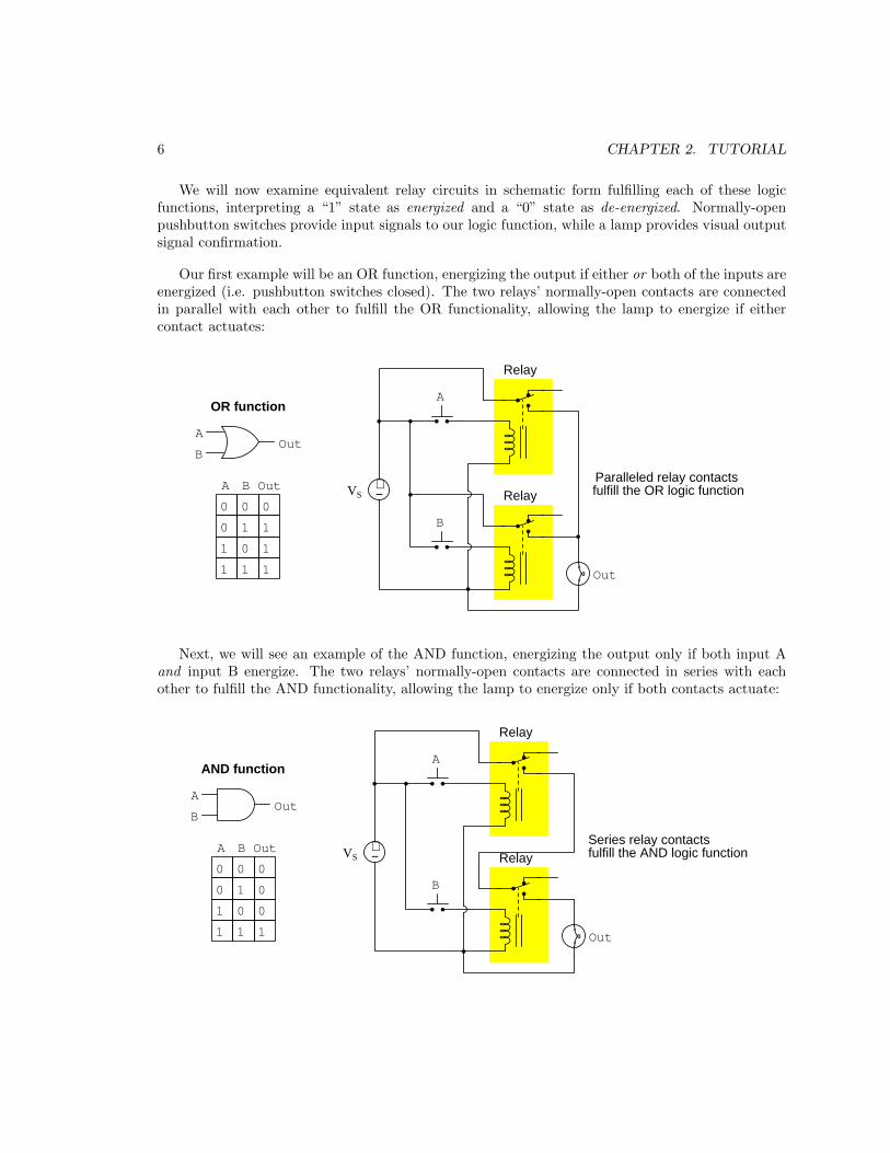
We will now examine equivalent relay circuits in schematic form fulfilling each of these logicfunctions, interpreting a “1” state as energized and a “0” state as de-energized. Normally-openpushbutton switches provide input signals to our logic function, while a lamp provides visual outputsignal confirmation.
Our first example will be an OR function, energizing the output if either or both of the inputs areenergized (i.e. pushbutton switches closed). The two relays’ normally-open contacts are connectedin parallel with each other to fulfill the OR functionality, allowing the lamp to energize if eithercontact actuates:
1
0
0
0
0
1
1 1
1
1
1
A B Out
OutA
B
OR function
0
A
B
Relay
Relay+−VS
Out
Paralleled relay contacts fulfill the OR logic function
Next, we will see an example of the AND function, energizing the output only if both input Aand input B energize. The two relays’ normally-open contacts are connected in series with eachother to fulfill the AND functionality, allowing the lamp to energize only if both contacts actuate:
1
0
0
0
0
1
1 1 1
A B Out
OutA
B
0
A
B
Relay
Relay+−VS
Out
0
0
AND function
Series relay contactsfulfill the AND logic function
7
The NOT function may be implemented in relay form by using the normally-closed (NC) relaycontact, so that it conducts electricity when the coil is de-energized and breaks the circuit when thecoil is energized. Attaching such a logical “inverter” to the output of the OR and AND relay circuitscreates NOR and NAND functions, respectively:
1
0
0
0
0
1
1 1
1
A B Out
OutA
B
A
B
+−VS
Out0
NOR function
0
0
1
0
0
0
0
1
1 1
1
A B Out
OutA
B
A
B
+−VS
Out0
NAND function
1
1
8 CHAPTER 2. TUTORIAL
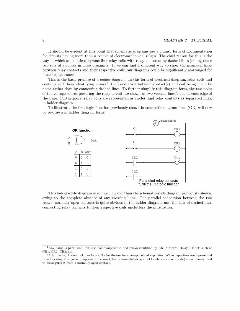
It should be evident at this point that schematic diagrams are a clumsy form of documentationfor circuits having more than a couple of electromechanical relays. The chief reason for this is theway in which schematic diagrams link relay coils with relay contacts: by dashed lines joining thosetwo sets of symbols in close proximity. If we can find a different way to show the magnetic linksbetween relay contacts and their respective coils, our diagrams could be significantly rearranged forneater appearance.
This is the basic premise of a ladder diagram. In this form of electrical diagram, relay coils andcontacts each bear identifying names1, the association between contact(s) and coil being made byname rather than by connecting dashed lines. To further simplify this diagram form, the two polesof the voltage source powering the relay circuit are shown as two vertical lines2, one at each edge ofthe page. Furthermore, relay coils are represented as circles, and relay contacts as separated lines,in ladder diagrams.
To illustrate, the first logic function previously shown in schematic diagram form (OR) will nowbe re-drawn in ladder diagram form:
1
0
0
0
0
1
1 1
1
1
1
A B Out
OutA
B
OR function
0
A
B
Out
Paralleled relay contacts fulfill the OR logic function
CR1
CR2
CR1
CR2
+ −
Voltage source
This ladder-style diagram is so much clearer than the schematic-style diagram previously shown,owing to the complete absence of any crossing lines. The parallel connection between the tworelays’ normally-open contacts is quite obvious in the ladder diagram, and the lack of dashed linesconnecting relay contacts to their respective coils unclutters the illustration.
1Any name is permitted, but it is commonplace to find relays identified by CR (“Control Relay”) labels such asCR1, CR2, CR3, etc.
2Admittedly, this symbol does look a like lot the one for a non-polarized capacitor. When capacitors are representedin ladder diagrams (which happens to be rare), the polarized-style symbol (with one curved plate) is commonly usedto distinguish it from a normally-open contact.
9
The ladder diagram for the AND logic function is just as clean and easy to interpret:
1
0
0
0
0
1
1 1 1
A B Out
OutA
B
0
A
B
Out
CR1
CR2
CR1 CR2
AND function
0
0Series relay contactsfulfill the AND logic function
Note how the voltage source has been omitted from the ladder diagram, just as we typicallyomit power supply “rail” terminals from operational amplifier and digital logic gate diagrams forthe sake of simplicity. In AC-powered relay circuits, the left-hand vertical line of the ladder diagramis typically labeled “L1” (line 1), and the right-hand vertical line “L2” (line 2). By convention,the right-hand line connection is usually connected to Earth ground, which makes it the neutral
conductor, while the left-hand line connection is ungrounded and therefore considered “hot”. Thesedetails are unimportant for the logical function of the circuit, but they are very important forconsiderations such as fusing (overcurrent protection)3 and general safety.
3Only ungrounded power conductors should be interrupted by overcurrent protection devices such as fuses and/orcircuit breakers, the grounded (neutral) conductor(s) always maintaining electrical commonality with Earth. Thismaintains as many conductors at Earth potential in a line-powered circuit as possible in all operating conditions, andensures “hot” conductors are disconnected following a high-current fault.
10 CHAPTER 2. TUTORIAL
Inversion (NOT) functions require normally-closed relay contacts, and the ladder diagram symbolfor this is a pair of separated lines with a diagonal line drawn through it to denote its normally-closed (NC) function. This will be illustrated in the following ladder diagrams for NOR and NANDfunctions, respectively:
1
0
0
0
0
1
1 1
1
A B Out
OutA
B
0
A
B
Out
CR1
CR2
CR1
CR2
CR3
CR3
NOR function
0
0
1
0
0
0
0
1
1 1
1
A B Out
OutA
B
0
A
B
Out
CR1
CR2
CR1 CR2
1
1
CR3
CR3
NAND function
It is very important to realize that the diagonal line drawn through a relay contact representsits normal state and not necessarily its present state or typical state. In fact, this is one of the mostcommon misconceptions for students first encountering ladder diagrams.
11
When analyzing the status of a relay circuit, it is useful to temporarily denote the live state ofeach and every contact and load in the circuit, in order to follow the logical relationships betweenthem. As just mentioned, the presence or absence of a diagonal line on a relay contact symboltells us nothing about its state at any given time, but only its state when at rest (i.e. relay coilde-energized). A convention I have grown to use for the purpose of annotating a ladder diagramwith live status is to draw a colored arrow or line just below any contact that is closed (to show itselectrical conductivity) and to draw a colored “X” symbol just below any contact that is open (toshow its lack of conductivity). The same arrow vs. “X” symbology is useful for denoting the stateof loads (e.g. relay coils, lamps) in the circuit.
To illustrate, let us apply these annotations to the NAND function relay circuit, for a conditionwhere A = 1 and B = 0:
1
0
0
0
0
1
1 1
1
A B Out
OutA
B
0
A
B
Out
CR1
CR2
CR1 CR2
1
1
CR3
CR3
NAND function
Legend:= closed switch or energized load= open switch or de-energized load
Note how each normally-open relay contact follows the status of its respective coil: a de-energizedrelay coil leaves its NO contact in the open state (e.g. CR2); an energized relay coil actuates itsNO contact to be closed (e.g. CR1). The one and only normally-closed relay contact in this circuitexhibits a state opposite that of its coil, as expected for an NC contact: a de-energized CR3 coilleaves NC contact CR3 in its resting (closed) state; if coil CR3 were to energize, it would actuatecontact CR3 to become open and turn off the lamp.
Again, it is very important to leave the relay contact symbols as they were originally drawn –NC contacts with diagonal lines, and NO contacts with none – because the presence or absence ofa diagonal line indicates the normal state of that contact, but not its actual4 state in any givencondition.
4An all-too-common tendency among students and working professionals alike is to draw diagonal lines to showwhen a contact closes, but this erroneously conflates normal status with present status. I have met many people whodo this, and I have also met many people who struggle to analyze complex ladder-diagram systems for precisely this
reason. I urge you to avoid this bad habit as you learn to drawn and analyze ladder diagrams!
12 CHAPTER 2. TUTORIAL
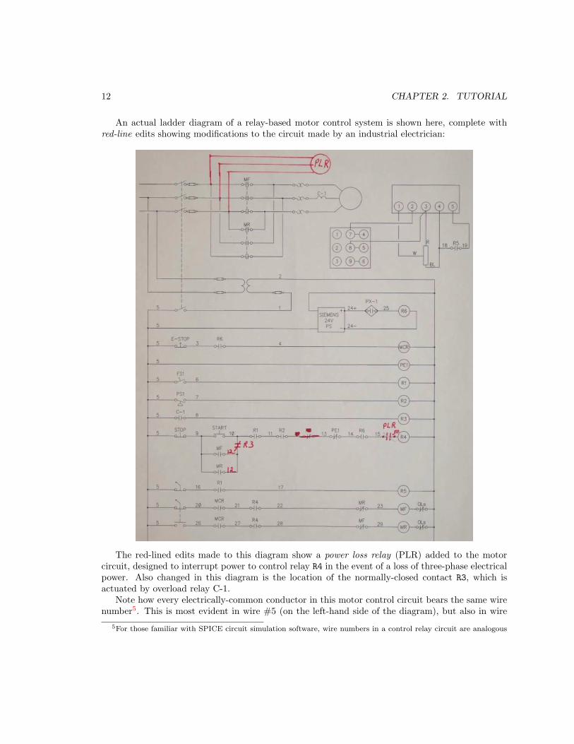
An actual ladder diagram of a relay-based motor control system is shown here, complete withred-line edits showing modifications to the circuit made by an industrial electrician:
The red-lined edits made to this diagram show a power loss relay (PLR) added to the motorcircuit, designed to interrupt power to control relay R4 in the event of a loss of three-phase electricalpower. Also changed in this diagram is the location of the normally-closed contact R3, which isactuated by overload relay C-1.
Note how every electrically-common conductor in this motor control circuit bears the same wirenumber5. This is most evident in wire #5 (on the left-hand side of the diagram), but also in wire
5For those familiar with SPICE circuit simulation software, wire numbers in a control relay circuit are analogous
13
#12 which is a new label with the relocation of relay contact R3, and also in wire #50 which is a newlabel with the addition of the PLR contact. Note how all electrically distinct wires (i.e. separatedfrom each other by one or more components) have differing wire numbers.
to node numbers in a SPICE netlist: identical numbers denote electrical commonality.
14 CHAPTER 2. TUTORIAL
Chapter 3
Historical References
This chapter is where you will find passages and/or illustrations from historical texts related to themodule’s topic.
Readers may wonder why historical references might be included in any modern lesson on asubject. Why dwell on old ideas and obsolete technologies? One answer to this question is that theinitial discoveries and early applications of scientific principles typically present those principles informs that are unusually easy to grasp. Anyone who first discovers a new principle must necessarilydo so from a perspective of ignorance (i.e. if you truly discover something yourself, it means you musthave come to that discovery with no prior knowledge of it and no hints from others knowledgeable init), and in so doing the discoverer lacks any hindsight or advantage that might have otherwise comefrom a more advanced perspective. Thus, discoverers are forced to think and express themselvesin less-advanced terms, and this often makes their explanations more readily accessible to otherswho, like the discoverer, comes to this idea with no prior knowledge. Furthermore, early discoverersoften faced the daunting challenge of explaining their new and complex ideas to a naturally skepticalscientific community, and this pressure incentivized clear and compelling communication. As JamesClerk Maxwell eloquently stated in the Preface to his book A Treatise on Electricity and Magnetism
written in 1873,
It is of great advantage to the student of any subject to read the original memoirs onthat subject, for science is always most completely assimilated when it is in its nascentstate . . . [page xi]
Furthermore, grasping the historical context of technological discoveries is important forunderstanding how science intersects with culture and civilization, which is ever important becausenew discoveries and new applications of existing discoveries will always continue to impact our lives.One will often find themselves impressed by the ingenuity of previous generations, and by the highdegree of refinement to which now-obsolete technologies were once raised. There is much to learnand much inspiration to be drawn from the technological past, and to the inquisitive mind thesehistorical references are treasures waiting to be (re)-discovered.
15
16 CHAPTER 3. HISTORICAL REFERENCES
3.1 New York City’s relay-based subway signal system
A very interesting historical example of a control system based on electromechanical relays is onethat is still in operation with portions of it over seventy years old1. This is the “interlocking” signalsystem employed by the New York City subway system, the purpose of which is to signal to humantrain operators when it is safe to move their train into a section of shared track. A report issued bythe Regional Plan Association in 2014 describes certain aspects of this signaling system:
Today, the New York City subway relies on a central nervous system made up of 15,000signal blocks, 3,500 mainline switches and 339,000 signal relays. These components,which have hardly changed since the subway opened in 1904, let train operators knowwhen it is safe for them to move trains forward. [page 5]
Another section of the RPA report describes how the subway tracks are divided into “blocks” offixed length, and how the presence of a subway car on the track is electrically detected by a relaycircuit:
The subway operates using a conventional fixed-block regime, meaning that its tracksare divided up into segments or blocks that average 1,000 feet in length. An insulatoris placed between the rails on both ends of the track segment to create a block. Anelectrical current is then run through the block to a relay creating an electrical circuit.As long as the circuit is closed, meaning that the current is able to travel unimpededfrom one end of the circuit through the relay to the other, the block is deemed openand not occupied by a train. As soon as a train enters a block its steel wheels breakor “short” the circuit causing the relay to discharge and the block to register as beingoccupied. The state of the blocks ahead dictates if or how fast a train may proceed alongits route. An open circuit can also indicate a broken rail or a signal malfunction. [page13]
The authors of this report were not necessarily writing for an audience of technicians or engineers,and so the terminology used to describe the electrical status of a track block is somewhat imprecise.However, it is clear that the metal wheels and axles of the subway cars act as electrical connectionsbridging one rail of an occupied “block” to the other rail, and that electrical connection divertscurrent that would otherwise pass through the coil of an electromechanical relay. The relay’s contactsthen cause colored signaling lamps to change state, much like the colored lamps of a traffic-controllight in a city street.
According to an article written by Dan Rivoli for the New York Daily News on 22 May 2017,the age of certain system components is impressive. Control relays manufactured by the GeneralRailway Signal Company (no longer in business) have labels with service dates from World WarTwo. Even many of the cables still used in this signaling system are old, dating back about 70 years.These cables use cloth fabric insulation rather than rubber or plastic, and are prone to catching fire.One upgrade strategy is to replace the older 120 Volt relays with 16 Volt relays, the reduced voltageposing less threat to the integrity of old cloth-insulated cables.
1Table 11 on 53 of RPA’s “Moving Forward” report shows three different lines on the New York City subway systemwith relay-based interlocking signals that have not been completely renewed in over 70 years, the oldest estimated tobe 78 years old. Twenty of the subway lines operate using relay-based controls at least 50 years old!
3.1. NEW YORK CITY’S RELAY-BASED SUBWAY SIGNAL SYSTEM 17
In another newspaper article written by Jeremy Smerd for the New York Sun in February 2005,the condition of rooms containing control relays for the subway signaling system was describedin terms revealing how antiquated the system is. Smerd’s article describes some of these roomsas lacking fire detection or suppression equipment, as well as lacking disconnect switches allowingfirefighters arriving on the scene to shut off electrical power before taking further action. A fire thatdestroyed control relays at the Chambers Street subway station in January 2005 was apparentlytriggered by something burning inside a shopping cart that was abandoned adjacent to the relayroom in a tunnel near the subway platform. Cloth-insulated cables passing from the relay room tothe tunnel caught fire, and the flammable cloth continued to burn into the relay room itself whereit destroyed the panel full of control relays.
18 CHAPTER 3. HISTORICAL REFERENCES
Chapter 4
Derivations and TechnicalReferences
This chapter is where you will find mathematical derivations too detailed to include in the tutorial,and/or tables and other technical reference material.
19
20 CHAPTER 4. DERIVATIONS AND TECHNICAL REFERENCES
4.1 Normal status of a switch contact
An perennial source of confusion among students new to electric switching circuits is the use of theword normal to refer to an electrical switch’s default state. Switches, of course, are discrete devicescapably only of two definite states: open (i.e. no electrical continuity) and closed (i.e. electricalcontinuity). Toggle switches are constructed in such a way that they may latch in either of thesetwo states, which means they have no default condition. A great many switch types, however, aredesigned with a spring-return mechanism or equivalent functionality to make the switch return to acertain default state in the absence of any external stimulus. This is called the “normal” state
of the switch: its electrical state when at rest.
Where this becomes confusing is in applications where such a switch is typically found in anactuated state, such that ordinary operating conditions for the circuit maintain that switch in itsnon-normal state. Colloquial use of the word “normal” is synonymous with “typical” which makesit possible for someone to see a switch’s “normal” status and mistakenly think this refers to itsstate in the circuit’s normal operation rather than meaning its “normal” status as defined by itsmanufacturer.
A brief illustration is helpful here. Consider a flow switch used to detect the presence of liquidcoolant flow through a pipe, carrying coolant to an operating engine. Engines, of course, dissipateheat as they run, and so a continuous flow of coolant to the engine is critical for maintaining safeoperating temperature. A simple diagram shows how this flow switch would be connected to awarning lamp to alert personnel of any interruption in coolant flow to the engine:
+ −
Voltage source
Flow switchLow flow
alarm lamp
(NC)
Since the purpose of this circuit is to energize the warning lamp in the event of no coolant flow,the flow switch’s spring-return mechanism must be configured in such a way to close the switchcontact in the absence of flow. In other words, this flow switch’s contact will be closed when at rest– i.e. it will be a normally-closed flow switch. However, during typical operation when adequatecoolant flow is present in the pipe, this switch will be held in its open state and the alarm lamp willbe de-energized. Even though the flow switch is normally-closed (NC), in this application it will betypically open – the “normal” and “typical” states for this switch in this application are opposite.
4.1. NORMAL STATUS OF A SWITCH CONTACT 21
Now consider the addition of a different type of switch and alarm lamp to the circuit, with thenew switch installed on the same heat-dissipating engine serving to warn personnel if the enginebecomes too hot:
+ −
Voltage source
Flow switch
Temperature switch
Low flowalarm lamp
High temperaturealarm lamp
(NC)
(NO)
This new switch’s purpose is to energize its warning lamp in the event the engine overheats, andits mechanism must be configured to close the switch in the presence of high temperature. Thismeans the temperature switch’s spring-return will force it open at rest, making it a normally-open
temperature switch. During typical operation when the engine’s temperature is within reasonablebounds, this switch will still be in its resting state, and so this normally-open (NO) temperatureswitch will also be typically open – a case where “normal” and “typical” states happen to be identical.
Let us consider one more switch application for this hypothetical engine, this time using a single-
pole, double-throw (SPDT ) speed switch to monitor the engine’s shaft speed and trigger energizationof two indicator lamps, one for “safe speed” and another for “overspeed”:
+ −
Voltage source
Flow switch
Temperature switch
Low flowalarm lamp
High temperaturealarm lamp
(NC)
(NO)
OverspeedSpeed switch
COM NO
NC
Safe speed
Note the COM, NO, and NC labeling of this switch’s three terminals, denoting “Common”,“Normally-Open”, and “Normally-Closed”, respectively. As with the other two switches, thesecontact labels as well as the switch symbol itself as drawn in the diagram represent the switch’sstate when at rest. This is strict convention in electrical switching circuits: the “normal” state ofany switch is defined by a condition of minimal stimulus, and this is always how it is drawn.
22 CHAPTER 4. DERIVATIONS AND TECHNICAL REFERENCES
A helpful tip to remember about sensing switches and their respective symbols is that the symbolsare conventionally drawn in such a way that an upward motion of the movable switch elementrepresents increasing stimulus. Here are some examples of this, showing various switch types andNO/NC contact configurations, comparing their states with no stimulus versus when the stimulusexceeds the each switch’s threshold or “trip” setting. The normal status of each switch as definedby the manufacturer is labeled in green text:
NO pressure switch NC pressure switch
Closed when pressure increases beyond threshold Open when pressure increases beyond threshold
NO level switch NC level switch
Open when there is zero level (minimum stimulus)Closed when level increases beyond threshold
Closed when there is zero pressure (minimum stimulus)Open when there is zero pressure (minimum stimulus)
Closed when there is zero level (minimum stimulus)Open when level increases beyond threshold
NO temperature switch NC temperature switch
Open when temperature is cold (minimum stimulus) Closed when temperature is cold (minimum stimulus)Closed when temperature increases beyond threshold Open when temperature increases beyond threshold
NO flow switch NC flow switch
Open when there is zero flow (minimum stimulus)Closed when flow increases beyond threshold
Closed when there is zero flow (minimum stimulus)Open when flow increases beyond threshold
Interestingly, the convention of upward motion representing the direction of stimulus is notmaintained for hand-operated switches.
4.1. NORMAL STATUS OF A SWITCH CONTACT 23
Switch contacts within electromechanical relays are also characterized as being either normally-open (NO) or normally-closed (NC), and in this case the stimulus in question is the energization ofthe relay’s electromagnet coil. When the coil is de-energized, the contacts will all be in their resting(i.e. “normal”) states which is also how the relay’s contacts are drawn in diagrams. When the coilis energized, though, all contacts within the relay flip to their opposite states: all NO contacts close
and all NC contacts open. The specific symbols used to represent relay coils and contacts differaccording to the type of diagram, but their meaning is the same:
A normally-closed (NC) relay contact is one which will be in its closed state when the coil isde-energized, represented in diagram form by touching lines or by a slash mark between the twocontact plates. A normally-open (NO) relay contact is one which will be in its open state whenthe coil is de-energized, represented in diagram form by an air gap between the contacting surfaces.Upon energization of the relay coil, all the contacts within that relay change state, but their written
symbols remain the same1 in order to represent their resting states.
1A bad habit some people adopt is to draw a slash mark through a relay contact symbol in order to annotatethat relay contact’s closure when analyzing the diagram for a relay-based circuit. This habit should avoided, as thesymbols used to represent normal status should never be used to represent present status. There is enough confusionas it is surrounding the term “normal” without any more being added, so please do not contribute to the chaos!
24 CHAPTER 4. DERIVATIONS AND TECHNICAL REFERENCES
When analyzing electrical switching circuits, a helpful problem-solving strategy is to annotatethe diagram with symbols denoting the actual status of each switch contact in any given circuitcondition, and not the normal status. Such annotations make it easier to determine which loads ina circuit will be energized, and which will not, for any given circuit condition. For this I recommendsketching an arrow or a line nearby a contact to show a closed state, and an “X” nearby a contact toshow an open state. These annotations demonstrate real contact status without obscuring normalstatus. Consider these annotations used in the following example diagram:
+ −
Voltage source
Pressure Temperaturetrip = 80 oC
CR1
Leveltrip = 10 cm
CR1
CR1
Solenoid
Lamp
60 kPa
trip = 35 kPa
51 oC
8 cm
Flowtrip = 12 lpm
3 lpm
In the upper “rung” of this ladder-style diagram we see the normally-open pressure switch isactuated (i.e. closed) because the applied pressure of 60 kPa exceeds the switch’s trip settingof 35 kPa. The normally-closed temperature switch is unactuated (i.e. closed) because the appliedtemperature of 51 oC is less than the trip threshold of 80 oC. The red arrows annotating both switchesshow their closed statuses. Wired in series, these two closed switch contacts permit energizing currentto the coil of relay CR1, and so another red arrow drawn there indicates that coil’s energized status.
In the second and third rungs we see the present status of each CR1 contact. Since the CR1relay coil is energized it places each CR1 relay contact into a state opposite of its “resting” or“normal” condition, therefore the normally-closed CR1 contact in rung 2 is open (shown with a red“X” annotation) and the normally-open CR1 contact in rung 3 is closed (shown with a red arrowannotation). The level switch’s stimulus is less than its trip setting, and so that normally-closedcontact remains closed and gets a red arrow. The flow switch’s stimulus is also less than its tripsetting, and so that normally-open switch remains open and gets a red “X” annotation. Neitherrung 2 nor rung 3 is completed because one of the series-connected contacts in each rung is open thuspreventing energization of its load. Therefore, both the solenoid coil and the lamp are de-energized,shown with red “X” annotations.
4.2. LADDER LOGIC PROGRAMMING OF PLCS 25
4.2 Ladder Logic Programming of PLCs
Ladder diagrams are such useful conventions for expressing discrete logic functions that they areeven used as a form of programming language for computer-based industrial control devices calledProgrammable Logic Controllers, or PLCs. Programmable logic controllers were developed to replacecomplex electromechanical relay logic circuits with something faster, more reliable, and more easilymodified. The basic idea of a PLC is that it receives discrete electrical signal inputs from switches,processes those input states according to a logic function drawn as a ladder diagram2, and thendrive output switching elements to send electricity to loads such as lamps, solenoids, and relay coils.
In order to demonstrate basic PLC functionality, I will present several illustrations of a PLCconnected to a pair of pushbutton switches, the PLC programmed using Relay Ladder Logic (RLL)3.The program is shown on a blue screen, as viewed from a personal computer connected to the PLC’sprocessor via a communication cable. Like practically all PLCs, this one reveals the current status ofits virtual “contacts” and “coils” by means of color highlighting on the personal computer screen, acolored contact or coil having a “true” state and an uncolored contact or coil having a “false” state.The particular program I will show in these examples implements a simple NAND logic function,and each illustration will show this NAND function in a different combinational state.
Close examination of each illustration is strongly recommended. Compare the truth table statesagainst the LED indicators on the PLC’s input and output modules, and also with the virtual“contacts” and “coils” visible within the RLL program screen.
2As though the PLC contained an array of easily-reconfigured relays inside.3Sometimes called Ladder Diagram, or LD.
26 CHAPTER 4. DERIVATIONS AND TECHNICAL REFERENCES
Processor Input0123
4567
IN0
IN1
IN2
IN3
IN4
IN5
IN6
IN7
COM
COM
Output0123
4567
COM
OUT1
OUT2
OUT3
OUT4
OUT5
OUT6
OUT7
OUT0
VDC
Programmable Logic Controller (PLC)
+−VS
A
B
IN2 IN5
OUT3
C1
C1
OUT
RLL program display
"Virtual" contacts and coilsinside the PLC processor’smemory
A
BOUT
A B OUT
0
0
0
01
1
1 1
1
1
1
0
NAND function
Switch A unpressedSwitch B unpressed
Processor Input0123
4567
IN0
IN1
IN2
IN3
IN4
IN5
IN6
IN7
COM
COM
Output0123
4567
COM
OUT1
OUT2
OUT3
OUT4
OUT5
OUT6
OUT7
OUT0
VDC
Programmable Logic Controller (PLC)
+−VS
A
B
IN2 IN5
OUT3
C1
C1
OUT
RLL program display
"Virtual" contacts and coilsinside the PLC processor’smemory
A
BOUT
A B OUT
0
0
0
01
1
1 1
1
1
1
0
NAND function
Switch A unpressedSwitch B pressed
4.2. LADDER LOGIC PROGRAMMING OF PLCS 27
Processor Input0123
4567
IN0
IN1
IN2
IN3
IN4
IN5
IN6
IN7
COM
COM
Output0123
4567
COM
OUT1
OUT2
OUT3
OUT4
OUT5
OUT6
OUT7
OUT0
VDC
Programmable Logic Controller (PLC)
+−VS
A
B
IN2 IN5
OUT3
C1
C1
OUT
RLL program display
Switch A pressedSwitch B unpressed
"Virtual" contacts and coilsinside the PLC processor’smemory
A
BOUT
A B OUT
0
0
0
01
1
1 1
1
1
1
0
NAND function
Processor Input0123
4567
IN0
IN1
IN2
IN3
IN4
IN5
IN6
IN7
COM
COM
Output0123
4567
COM
OUT1
OUT2
OUT3
OUT4
OUT5
OUT6
OUT7
OUT0
VDC
Programmable Logic Controller (PLC)
+−VS
A
B
IN2 IN5
OUT3
C1
C1
OUT
RLL program display
"Virtual" contacts and coilsinside the PLC processor’smemory
A
BOUT
A B OUT
0
0
0
01
1
1 1
1
1
1
0
NAND function
Switch A pressedSwitch B pressed
“Ladder-logic” programming is limited compared to text-based computer programminglanguages, but it is far more intuitive and resembles the diagrams of relay control systems PLCs weredesigned to replace. Some modern PLCs support text-based and function-block-based programminglanguages in addition to RLL, in order to give the end-user an array of programming options.
28 CHAPTER 4. DERIVATIONS AND TECHNICAL REFERENCES
Chapter 5
Questions
This learning module, along with all others in the ModEL collection, is designed to be used in aninverted instructional environment where students independently read1 the tutorials and attemptto answer questions on their own prior to the instructor’s interaction with them. In place oflecture2, the instructor engages with students in Socratic-style dialogue, probing and challengingtheir understanding of the subject matter through inquiry.
Answers are not provided for questions within this chapter, and this is by design. Solved problemsmay be found in the Tutorial and Derivation chapters, instead. The goal here is independence, andthis requires students to be challenged in ways where others cannot think for them. Rememberthat you always have the tools of experimentation and computer simulation (e.g. SPICE) to exploreconcepts!
The following lists contain ideas for Socratic-style questions and challenges. Upon inspection,one will notice a strong theme of metacognition within these statements: they are designed to fostera regular habit of examining one’s own thoughts as a means toward clearer thinking. As such thesesample questions are useful both for instructor-led discussions as well as for self-study.
1Technical reading is an essential academic skill for any technical practitioner to possess for the simple reasonthat the most comprehensive, accurate, and useful information to be found for developing technical competence is intextual form. Technical careers in general are characterized by the need for continuous learning to remain currentwith standards and technology, and therefore any technical practitioner who cannot read well is handicapped intheir professional development. An excellent resource for educators on improving students’ reading prowess throughintentional effort and strategy is the book textitReading For Understanding – How Reading Apprenticeship ImprovesDisciplinary Learning in Secondary and College Classrooms by Ruth Schoenbach, Cynthia Greenleaf, and LynnMurphy.
2Lecture is popular as a teaching method because it is easy to implement: any reasonably articulate subject matterexpert can talk to students, even with little preparation. However, it is also quite problematic. A good lecture alwaysmakes complicated concepts seem easier than they are, which is bad for students because it instills a false sense ofconfidence in their own understanding; reading and re-articulation requires more cognitive effort and serves to verifycomprehension. A culture of teaching-by-lecture fosters a debilitating dependence upon direct personal instruction,whereas the challenges of modern life demand independent and critical thought made possible only by gatheringinformation and perspectives from afar. Information presented in a lecture is ephemeral, easily lost to failures ofmemory and dictation; text is forever, and may be referenced at any time.
29
30 CHAPTER 5. QUESTIONS
General challenges following tutorial reading
• Summarize as much of the text as you can in one paragraph of your own words. A helpfulstrategy is to explain ideas as you would for an intelligent child: as simple as you can withoutcompromising too much accuracy.
• Simplify a particular section of the text, for example a paragraph or even a single sentence, soas to capture the same fundamental idea in fewer words.
• Where did the text make the most sense to you? What was it about the text’s presentationthat made it clear?
• Identify where it might be easy for someone to misunderstand the text, and explain why youthink it could be confusing.
• Identify any new concept(s) presented in the text, and explain in your own words.
• Identify any familiar concept(s) such as physical laws or principles applied or referenced in thetext.
• Devise a proof of concept experiment demonstrating an important principle, physical law, ortechnical innovation represented in the text.
• Devise an experiment to disprove a plausible misconception.
• Did the text reveal any misconceptions you might have harbored? If so, describe themisconception(s) and the reason(s) why you now know them to be incorrect.
• Describe any useful problem-solving strategies applied in the text.
• Devise a question of your own to challenge a reader’s comprehension of the text.
31
General follow-up challenges for assigned problems
• Identify where any fundamental laws or principles apply to the solution of this problem,especially before applying any mathematical techniques.
• Devise a thought experiment to explore the characteristics of the problem scenario, applyingknown laws and principles to mentally model its behavior.
• Describe in detail your own strategy for solving this problem. How did you identify andorganized the given information? Did you sketch any diagrams to help frame the problem?
• Is there more than one way to solve this problem? Which method seems best to you?
• Show the work you did in solving this problem, even if the solution is incomplete or incorrect.
• What would you say was the most challenging part of this problem, and why was it so?
• Was any important information missing from the problem which you had to research or recall?
• Was there any extraneous information presented within this problem? If so, what was it andwhy did it not matter?
• Examine someone else’s solution to identify where they applied fundamental laws or principles.
• Simplify the problem from its given form and show how to solve this simpler version of it.Examples include eliminating certain variables or conditions, altering values to simpler (usuallywhole) numbers, applying a limiting case (i.e. altering a variable to some extreme or ultimatevalue).
• For quantitative problems, identify the real-world meaning of all intermediate calculations:their units of measurement, where they fit into the scenario at hand. Annotate any diagramsor illustrations with these calculated values.
• For quantitative problems, try approaching it qualitatively instead, thinking in terms of“increase” and “decrease” rather than definite values.
• For qualitative problems, try approaching it quantitatively instead, proposing simple numericalvalues for the variables.
• Were there any assumptions you made while solving this problem? Would your solution changeif one of those assumptions were altered?
• Identify where it would be easy for someone to go astray in attempting to solve this problem.
• Formulate your own problem based on what you learned solving this one.
General follow-up challenges for experiments or projects
• In what way(s) was this experiment or project easy to complete?
• Identify some of the challenges you faced in completing this experiment or project.
32 CHAPTER 5. QUESTIONS
• Show how thorough documentation assisted in the completion of this experiment or project.
• Which fundamental laws or principles are key to this system’s function?
• Identify any way(s) in which one might obtain false or otherwise misleading measurementsfrom test equipment in this system.
• What will happen if (component X) fails (open/shorted/etc.)?
• What would have to occur to make this system unsafe?
5.1. CONCEPTUAL REASONING 33
5.1 Conceptual reasoning
These questions are designed to stimulate your analytic and synthetic thinking3. In a Socraticdiscussion with your instructor, the goal is for these questions to prompt an extended dialoguewhere assumptions are revealed, conclusions are tested, and understanding is sharpened. Yourinstructor may also pose additional questions based on those assigned, in order to further probe andrefine your conceptual understanding.
Questions that follow are presented to challenge and probe your understanding of various conceptspresented in the tutorial. These questions are intended to serve as a guide for the Socratic dialoguebetween yourself and the instructor. Your instructor’s task is to ensure you have a sound grasp ofthese concepts, and the questions contained in this document are merely a means to this end. Yourinstructor may, at his or her discretion, alter or substitute questions for the benefit of tailoring thediscussion to each student’s needs. The only absolute requirement is that each student is challengedand assessed at a level equal to or greater than that represented by the documented questions.
It is far more important that you convey your reasoning than it is to simply convey a correctanswer. For this reason, you should refrain from researching other information sources to answerquestions. What matters here is that you are doing the thinking. If the answer is incorrect, yourinstructor will work with you to correct it through proper reasoning. A correct answer without anadequate explanation of how you derived that answer is unacceptable, as it does not aid the learningor assessment process.
You will note a conspicuous lack of answers given for these conceptual questions. Unlike standardtextbooks where answers to every other question are given somewhere toward the back of the book,here in these learning modules students must rely on other means to check their work. The best wayby far is to debate the answers with fellow students and also with the instructor during the Socraticdialogue sessions intended to be used with these learning modules. Reasoning through challengingquestions with other people is an excellent tool for developing strong reasoning skills.
Another means of checking your conceptual answers, where applicable, is to use circuit simulationsoftware to explore the effects of changes made to circuits. For example, if one of these conceptualquestions challenges you to predict the effects of altering some component parameter in a circuit,you may check the validity of your work by simulating that same parameter change within softwareand seeing if the results agree.
3Analytical thinking involves the “disassembly” of an idea into its constituent parts, analogous to dissection.Synthetic thinking involves the “assembly” of a new idea comprised of multiple concepts, analogous to construction.Both activities are high-level cognitive skills, extremely important for effective problem-solving, necessitating frequentchallenge and regular practice to fully develop.
34 CHAPTER 5. QUESTIONS
5.1.1 Reading outline and reflections
“Reading maketh a full man; conference a ready man; and writing an exact man” – Francis Bacon
Francis Bacon’s advice is a blueprint for effective education: reading provides the learner withknowledge, writing focuses the learner’s thoughts, and critical dialogue equips the learner toconfidently communicate and apply their learning. Independent acquisition and application ofknowledge is a powerful skill, well worth the effort to cultivate. To this end, students shouldread these educational resources closely, write their own outline and reflections on the reading, anddiscuss in detail their findings with classmates and instructor(s). You should be able to do all of thefollowing after reading any instructional text:
√Briefly OUTLINE THE TEXT, as though you were writing a detailed Table of Contents. Feel
free to rearrange the order if it makes more sense that way. Prepare to articulate these points indetail and to answer questions from your classmates and instructor. Outlining is a good self-test ofthorough reading because you cannot outline what you have not read or do not comprehend.
√Demonstrate ACTIVE READING STRATEGIES, including verbalizing your impressions as
you read, simplifying long passages to convey the same ideas using fewer words, annotating textand illustrations with your own interpretations, working through mathematical examples shown inthe text, cross-referencing passages with relevant illustrations and/or other passages, identifyingproblem-solving strategies applied by the author, etc. Technical reading is a special case of problem-solving, and so these strategies work precisely because they help solve any problem: paying attentionto your own thoughts (metacognition), eliminating unnecessary complexities, identifying what makessense, paying close attention to details, drawing connections between separated facts, and notingthe successful strategies of others.
√Identify IMPORTANT THEMES, especially GENERAL LAWS and PRINCIPLES, expounded
in the text and express them in the simplest of terms as though you were teaching an intelligentchild. This emphasizes connections between related topics and develops your ability to communicatecomplex ideas to anyone.
√Form YOUR OWN QUESTIONS based on the reading, and then pose them to your instructor
and classmates for their consideration. Anticipate both correct and incorrect answers, the incorrectanswer(s) assuming one or more plausible misconceptions. This helps you view the subject fromdifferent perspectives to grasp it more fully.
√Devise EXPERIMENTS to test claims presented in the reading, or to disprove misconceptions.
Predict possible outcomes of these experiments, and evaluate their meanings: what result(s) wouldconfirm, and what would constitute disproof? Running mental simulations and evaluating results isessential to scientific and diagnostic reasoning.
√Specifically identify any points you found CONFUSING. The reason for doing this is to help
diagnose misconceptions and overcome barriers to learning.
5.1. CONCEPTUAL REASONING 35
5.1.2 Foundational concepts
Correct analysis and diagnosis of electric circuits begins with a proper understanding of some basicconcepts. The following is a list of some important concepts referenced in this module’s full tutorial.Define each of them in your own words, and be prepared to illustrate each of these concepts with adescription of a practical example and/or a live demonstration.
Discrete signal
Logic function
Truth table
OR function
AND function
NOT function
NOR function
NAND function
Parallel contact logic
Series contact logic
Normally-closed contact logic
Normal state of a switch
36 CHAPTER 5. QUESTIONS
Relay ladder diagram
Annotating relay states
Wire numbering
5.1. CONCEPTUAL REASONING 37
5.1.3 Conveyor warning siren
An electric motor is used to power a large conveyor belt. Before the motor actually starts, awarning siren activates to alert workers of the conveyor’s forthcoming action. The following relaycircuit accomplishes both tasks (motor control plus siren alert). M1 is a “motor contactor” whichis nothing more than a large relay with high-current-rated contacts (not shown here) used to makeand break power to the electric motor moving the conveyor belt:
L1 L2
OLTD1
M1
M1TD1
Siren
Run
MotorTo motor
powersource
M1
Study this ladder logic diagram, then explain how the system works.
Challenges
• Supposing the electric motor was powered by the same line connections (L1 and L2) as thisrelay control circuit, where would it be inserted into this diagram.
• Suppose contactor M1 only had one electrical switch contact, and that was the one for motorpower. In the absence of a normally-closed “auxiliary” contact used here to control the siren,how could this same warning siren be controlled? What else would you have to add to thiscircuit, and where exactly would it go?
38 CHAPTER 5. QUESTIONS
5.1.4 Active reading exercise: motor control circuit diagram
A good habit when reading technical documents is to read them actively, which means among otherthings analyzing the information presented to you rather than just trying to absorb it. An applicationof this is the image of a motor control ladder diagram in the Tutorial, where someone had made“red-line” edits to the diagram after installing a Power Loss Relay (PLR). A reader could merelyexamine the diagram, read the accompanying text, and move on, but they will learn a lot more ifthey try to analyze that diagram to see how the motor control system is supposed to function.
Examine this diagram closely, and then answer the following questions about it:
• Identify the relay coil which needs to be energized in order to make the three-phase AC motorspin in the “forward” direction.
• Identify the relay coil which needs to be energized in order to make the three-phase AC motorspin in the “reverse” direction.
• Explain how pressing the Emergency Stop (“E-Stop”) latching pushbutton forces the motorto stop.
• Pressing the momentary-contact Start pushbutton causes the motor to run and remain runningeven after that Start pushbutton is released. How does this circuit achieve a “latching” functionto keep the motor running even after the Start pushbutton switch returns to its normal (open)state?
• Where did new wire numbers have to be inserted into this circuit, and why were new numbersnecessary?
• Proximity switch PX-1 is an example of a permissive contact, because it needs to sense thepresence of a machine part before permitting the motor to run in either direction. Note theunusual way in which PX-1 is wired into the circuit, which is unlike how any of the otherswitches (e.g. PS1, FS1. E-Stop, etc.) are wired. Explain why this is.
Challenges
• What purpose do you suppose the Power Loss Relay serves?
5.2. QUANTITATIVE REASONING 39
5.2 Quantitative reasoning
These questions are designed to stimulate your computational thinking. In a Socratic discussion withyour instructor, the goal is for these questions to reveal your mathematical approach(es) to problem-solving so that good technique and sound reasoning may be reinforced. Your instructor may also poseadditional questions based on those assigned, in order to observe your problem-solving firsthand.
Mental arithmetic and estimations are strongly encouraged for all calculations, because withoutthese abilities you will be unable to readily detect errors caused by calculator misuse (e.g. keystrokeerrors).
You will note a conspicuous lack of answers given for these quantitative questions. Unlikestandard textbooks where answers to every other question are given somewhere toward the backof the book, here in these learning modules students must rely on other means to check their work.My advice is to use circuit simulation software such as SPICE to check the correctness of quantitativeanswers. Refer to those learning modules within this collection focusing on SPICE to see workedexamples which you may use directly as practice problems for your own study, and/or as templatesyou may modify to run your own analyses and generate your own practice problems.
Completely worked example problems found in the Tutorial may also serve as “test cases4” forgaining proficiency in the use of circuit simulation software, and then once that proficiency is gainedyou will never need to rely5 on an answer key!
4In other words, set up the circuit simulation software to analyze the same circuit examples found in the Tutorial.If the simulated results match the answers shown in the Tutorial, it confirms the simulation has properly run. Ifthe simulated results disagree with the Tutorial’s answers, something has been set up incorrectly in the simulationsoftware. Using every Tutorial as practice in this way will quickly develop proficiency in the use of circuit simulationsoftware.
5This approach is perfectly in keeping with the instructional philosophy of these learning modules: teaching students
to be self-sufficient thinkers. Answer keys can be useful, but it is even more useful to your long-term success to havea set of tools on hand for checking your own work, because once you have left school and are on your own, there willno longer be “answer keys” available for the problems you will have to solve.
40 CHAPTER 5. QUESTIONS
5.2.1 Introduction to spreadsheets
A powerful computational tool you are encouraged to use in your work is a spreadsheet. Availableon most personal computers (e.g. Microsoft Excel), spreadsheet software performs numericalcalculations based on number values and formulae entered into cells of a grid. This grid istypically arranged as lettered columns and numbered rows, with each cell of the grid identifiedby its column/row coordinates (e.g. cell B3, cell A8). Each cell may contain a string of text, anumber value, or a mathematical formula. The spreadsheet automatically updates the results of allmathematical formulae whenever the entered number values are changed. This means it is possibleto set up a spreadsheet to perform a series of calculations on entered data, and those calculationswill be re-done by the computer any time the data points are edited in any way.
For example, the following spreadsheet calculates average speed based on entered values ofdistance traveled and time elapsed:
1
2
3
4
5
A B C
Distance traveled
Time elapsed
Kilometers
Hours
Average speed km/h
D
46.9
1.18
= B1 / B2
Text labels contained in cells A1 through A3 and cells C1 through C3 exist solely for readabilityand are not involved in any calculations. Cell B1 contains a sample distance value while cell B2contains a sample time value. The formula for computing speed is contained in cell B3. Note howthis formula begins with an “equals” symbol (=), references the values for distance and speed bylettered column and numbered row coordinates (B1 and B2), and uses a forward slash symbol fordivision (/). The coordinates B1 and B2 function as variables6 would in an algebraic formula.
When this spreadsheet is executed, the numerical value 39.74576 will appear in cell B3 ratherthan the formula = B1 / B2, because 39.74576 is the computed speed value given 46.9 kilometerstraveled over a period of 1.18 hours. If a different numerical value for distance is entered into cellB1 or a different value for time is entered into cell B2, cell B3’s value will automatically update. Allyou need to do is set up the given values and any formulae into the spreadsheet, and the computerwill do all the calculations for you.
Cell B3 may be referenced by other formulae in the spreadsheet if desired, since it is a variablejust like the given values contained in B1 and B2. This means it is possible to set up an entire chainof calculations, one dependent on the result of another, in order to arrive at a final value. Thearrangement of the given data and formulae need not follow any pattern on the grid, which meansyou may place them anywhere.
6Spreadsheets may also provide means to attach text labels to cells for use as variable names (Microsoft Excelsimply calls these labels “names”), but for simple spreadsheets such as those shown here it’s usually easier just to usethe standard coordinate naming for each cell.
5.2. QUANTITATIVE REASONING 41
Common7 arithmetic operations available for your use in a spreadsheet include the following:
• Addition (+)
• Subtraction (-)
• Multiplication (*)
• Division (/)
• Powers (^)
• Square roots (sqrt())
• Logarithms (ln() , log10())
Parentheses may be used to ensure8 proper order of operations within a complex formula.Consider this example of a spreadsheet implementing the quadratic formula, used to solve for rootsof a polynomial expression in the form of ax2 + bx + c:
x =−b ±
√b2 − 4ac
2a
1
2
3
4
5
A B
5
-2
x_1
x_2
a =
b =
c =
9
= (-B4 - sqrt((B4^2) - (4*B3*B5))) / (2*B3)
= (-B4 + sqrt((B4^2) - (4*B3*B5))) / (2*B3)
This example is configured to compute roots9 of the polynomial 9x2 + 5x− 2 because the valuesof 9, 5, and −2 have been inserted into cells B3, B4, and B5, respectively. Once this spreadsheet hasbeen built, though, it may be used to calculate the roots of any second-degree polynomial expressionsimply by entering the new a, b, and c coefficients into cells B3 through B5. The numerical valuesappearing in cells B1 and B2 will be automatically updated by the computer immediately followingany changes made to the coefficients.
7Modern spreadsheet software offers a bewildering array of mathematical functions you may use in yourcomputations. I recommend you consult the documentation for your particular spreadsheet for information onoperations other than those listed here.
8Spreadsheet programs, like text-based programming languages, are designed to follow standard order of operationsby default. However, my personal preference is to use parentheses even where strictly unnecessary just to make itclear to any other person viewing the formula what the intended order of operations is.
9Reviewing some algebra here, a root is a value for x that yields an overall value of zero for the polynomial. Forthis polynomial (9x
2 +5x−2) the two roots happen to be x = 0.269381 and x = −0.82494, with these values displayedin cells B1 and B2, respectively upon execution of the spreadsheet.
42 CHAPTER 5. QUESTIONS
Alternatively, one could break up the long quadratic formula into smaller pieces like this:
y =√
b2 − 4ac z = 2a
x =−b ± y
z
1
2
3
4
5
A B
5
-2
x_1
x_2
a =
b =
c =
9
C
= sqrt((B4^2) - (4*B3*B5))
= 2*B3
= (-B4 + C1) / C2
= (-B4 - C1) / C2
Note how the square-root term (y) is calculated in cell C1, and the denominator term (z) in cellC2. This makes the two final formulae (in cells B1 and B2) simpler to interpret. The positioning ofall these cells on the grid is completely arbitrary10 – all that matters is that they properly referenceeach other in the formulae.
Spreadsheets are particularly useful for situations where the same set of calculations representinga circuit or other system must be repeated for different initial conditions. The power of a spreadsheetis that it automates what would otherwise be a tedious set of calculations. One specific applicationof this is to simulate the effects of various components within a circuit failing with abnormal values(e.g. a shorted resistor simulated by making its value nearly zero; an open resistor simulated bymaking its value extremely large). Another application is analyzing the behavior of a circuit designgiven new components that are out of specification, and/or aging components experiencing driftover time.
5.2.2 Introduction to computer programming
A powerful tool for mathematical modeling is text-based computer programming. This is whereyou type coded commands in text form which the computer is able to interpret. Many differenttext-based languages exist for this purpose, but we will focus here on just two of them, C++ andPython.
10My personal preference is to locate all the “given” data in the upper-left cells of the spreadsheet grid (each datapoint flanked by a sensible name in the cell to the left and units of measurement in the cell to the right as illustratedin the first distance/time spreadsheet example), sometimes coloring them in order to clearly distinguish which cellscontain entered data versus which cells contain computed results from formulae. I like to place all formulae in cellsbelow the given data, and try to arrange them in logical order so that anyone examining my spreadsheet will be ableto figure out how I constructed a solution. This is a general principle I believe all computer programmers shouldfollow: document and arrange your code to make it easy for other people to learn from it.
5.2. QUANTITATIVE REASONING 43
Programming in C++
One of the more popular text-based computer programming languages is called C++. This is acompiled language, which means you must create a plain-text file containing C++ code using aprogram called a text editor, then execute a software application called a compiler to translate your“source code” into instructions directly understandable to the computer. Here is an example of“source code” for a very simple C++ program intended to perform some basic arithmetic operationsand print the results to the computer’s console:
cout << "the two numbers " << x << " and " << y << " and then" << endl;
cout << "displays the results on the computer’s console." << endl;
cout << endl;
cout << "Sum = " << x + y << endl;
cout << "Difference = " << x - y << endl;
cout << "Product = " << x * y << endl;
cout << "Quotient of " << x / y << endl;
return 0;
Computer languages such as C++ are designed to make sense when read by human programmers.The general order of execution is left-to-right, top-to-bottom just the same as reading any textdocument written in English. Blank lines, indentation, and other “whitespace” is largely irrelevantin C++ code, and is included only to make the code more pleasing11 to view.
11Although not included in this example, comments preceded by double-forward slash characters (//) may be addedto source code as well to provide explanations of what the code is supposed to do, for the benefit of anyone readingit. The compiler application will ignore all comments.
44 CHAPTER 5. QUESTIONS
Let’s examine the C++ source code line by line to explain what it means:
• #include <iostream> and using namespace std; are set-up instructions to the compilergiving it some context in which to interpret your code. The code specific to your task is locatedbetween the brace symbols ( and ).
• int main() labels the “Main” function for the computer: the instructions within this function(lying between the and symbols) it will be commanded to execute. Every complete C++program contains a main function at minimum, and often additional functions as well. Theint declares this function will return an integer number value when complete, which helps toexplain the purpose of the return 0; statement at the end of the main function: providing anumerical value of zero at the program’s completion as promised by int. This returned value israther incidental to our purpose here, but it is fairly standard practice in C++ programming.
• The float declaration reserves places in the computer’s memory for two floating-point variables,in this case the variables’ names being x and y.
• The next two lines assign numerical values to the two variables. Note how each line terminateswith a semicolon character (;) and how this pattern holds true for most of the lines in thisprogram.
• All the other instructions take the form of a cout command which prints characters tothe “standard output” stream of the computer, which in this case will be text displayedon the console. The double-less-than symbols (<<) show data being sent toward the cout
command. Note how verbatim text is enclosed in quotation marks, while variables such as x
or mathematical expressions such as x - y are not enclosed in quotations because we wantthe computer to display the numerical values represented, not the literal text.
• The endl found at the end of every cout statement marks the end of a line of text. If not forthese endl inclusions, the text displayed on the computer’s screen would resemble a run-onsentence rather than a paragraph. Note the cout << endl; line, which does nothing butcreate a blank line on the screen, for no reason other than esthetics.
After saving this source code text to a file with its own name (e.g. myprogram.cpp), you wouldthen compile this source code into an executable file which the computer may then run. If you areusing a console-based compiler such as GCC (very popular within variants of the Unix operatingsystem12, such as Linux and Apple’s OS X), you would type the following command and press theEnter key:
g++ -o myprogram.exe myprogram.cpp
This command instructs the GCC compiler to take your source code (myprogram.cpp) and createwith it an executable file named myprogram.exe. Simply typing ./myprogram.exe at the command-line will then execute your program:
./myprogram.exe
12A very functional option for users of Microsoft Windows is called Cygwin, which provides a Unix-like consoleenvironment complete with all the customary utility applications such as GCC!
5.2. QUANTITATIVE REASONING 45
If you are using a graphic-based C++ development system such as Microsoft Visual Studio13, youmay simply create a new console application “project” using this software, then paste or type yourcode into the example template appearing in the editor window, and finally run your application totest its output.
As this program runs, it displays the following text to the console:
This simple program performs basic arithmetic on
the two numbers 200 and -560.5 and then
displays the results on the computer’s console.
Sum = -360.5
Difference = 760.5
Product = -112100
Quotient of -0.356824
As crude as this example program is, it serves the purpose of showing how easy it is to write andexecute simple programs in a computer using the C++ language. As you encounter C++ exampleprograms (shown as source code) in any of these modules, feel free to directly copy-and-paste thesource code text into a text editor’s screen, then follow the rest of the instructions given here (i.e.save to a file, compile, and finally run your program). You will find that it is generally easier tolearn computer programming by closely examining others’ example programs and modifying themthan it is to write your own programs starting from a blank screen.
13Using Microsoft Visual Studio community version 2017 at the time of this writing to test this example, here arethe steps I needed to follow in order to successfully compile and run a simple program such as this: (1) Start upVisual Studio and select the option to create a New Project; (2) Select the Windows Console Application template,as this will perform necessary set-up steps to generate a console-based program which will save you time and effortas well as avoid simple errors of omission; (3) When the editing screen appears, type or paste the C++ code withinthe main() function provided in the template, deleting the “Hello World” cout line that came with the template; (4)Type or paste any preprocessor directives (e.g. #include statements, namespace statements) necessary for your codethat did not come with the template; (5) Lastly, under the Debug drop-down menu choose either Start Debugging(F5 hot-key) or Start Without Debugging (Ctrl-F5 hotkeys) to compile (“Build”) and run your new program. Uponexecution a console window will appear showing the output of your program.
46 CHAPTER 5. QUESTIONS
Programming in Python
Another text-based computer programming language called Python allows you to type instructionsat a terminal prompt and receive immediate results without having to compile that code. Thisis because Python is an interpreted language: a software application called an interpreter readsyour source code, translates it into computer-understandable instructions, and then executes thoseinstructions in one step.
The following shows what happens on my personal computer when I start up the Pythoninterpreter on my personal computer, by typing python314 and pressing the Enter key:
Python 3.7.2 (default, Feb 19 2019, 18:15:18)
[GCC 4.1.2] on linux
Type "help", "copyright", "credits" or "license" for more information.
>>>
The >>> symbols represent the prompt within the Python interpreter “shell”, signifying readinessto accept Python commands entered by the user.
Shown here is an example of the same arithmetic operations performed on the same quantities,using a Python interpreter. All lines shown preceded by the >>> prompt are entries typed by thehuman programmer, and all lines shown without the >>> prompt are responses from the Pythoninterpreter software:
>>> x = 200
>>> y = -560.5
>>> x + y
-360.5
>>> x - y
760.5
>>> x * y
-112100.0
>>> x / y
-0.35682426404995538
>>> quit()
14Using version 3 of Python, which is the latest at the time of this writing.
5.2. QUANTITATIVE REASONING 47
More advanced mathematical functions are accessible in Python by first entering the line from
math import * which “imports” these functions from Python’s math library (included on anycomputer with Python installed). Some examples show some of these functions in use, demonstratinghow the Python interpreter may be used as a scientific calculator:
>>> from math import *
>>> sin(30.0)
-0.98803162409286183
>>> sin(radians(30.0))
0.49999999999999994
>>> pow(2.0, 5.0)
32.0
>>> log10(10000.0)
4.0
>>> e
2.7182818284590451
>>> pi
3.1415926535897931
>>> log(pow(e,6.0))
6.0
>>> asin(0.7071068)
0.78539819000368838
>>> degrees(asin(0.7071068))
45.000001524425265
>>> a = complex(3.0,4.0)
>>> b = complex(-2.8,10.5)
>>> a + b
(0.20000000000000018+14.5j)
>>> a - b
(5.8-6.5j)
>>> a * b
(-50.4+20.3j)
>>> a / b
(0.2845287492590397-0.36158861885002963j)
>>> quit()
Note how trigonometric functions assume angles expressed in radians rather than degrees, andhow Python provides convenient functions for translating between the two. Logarithms assume abase of e unless otherwise stated (e.g. the log10 function for common logarithms).
The interpreted (versus compiled) nature of Python, as well as its relatively simple syntax, makesit a good choice as a person’s first programming language. For complex applications, interpretedlanguages such as Python execute slower than compiled languages such as C++, but for the verysimple examples used in these learning modules speed is not a concern.
48 CHAPTER 5. QUESTIONS
Another Python math library is cmath, giving Python the ability to perform arithmetic oncomplex numbers. This is very useful for AC circuit analysis using phasors15 as shown in thefollowing example. Here we see Python’s interpreter used as a scientific calculator to show seriesand parallel impedances of a resistor, capacitor, and inductor in a 60 Hz AC circuit:
>>> from math import *
>>> from cmath import *
>>> r = complex(400,0)
>>> f = 60.0
>>> xc = 1/(2 * pi * f * 4.7e-6)
>>> zc = complex(0,-xc)
>>> xl = 2 * pi * f * 1.0
>>> zl = complex(0,xl)
>>> r + zc + zl
(400-187.38811239154882j)
>>> 1/(1/r + 1/zc + 1/zl)
(355.837695813625+125.35793777619385j)
>>> polar(r + zc + zl)
(441.717448903332, -0.4381072059213295)
>>> abs(r + zc + zl)
441.717448903332
>>> phase(r + zc + zl)
-0.4381072059213295
>>> degrees(phase(r + zc + zl))
-25.10169387356105
Note how Python defaults to rectangular form for complex quantities. Here we defined a 400Ohm resistance as a complex value in rectangular form (400 +j0 Ω), then computed capacitive andinductive reactances at 60 Hz and defined each of those as complex (phasor) values (0− jXc Ω and0+ jXl Ω, respectively). After that we computed total impedance in series, then total impedance inparallel. Polar-form representation was then shown for the series impedance (441.717 Ω 6 −25.102o).Note the use of different functions to show the polar-form series impedance value: polar() takesthe complex quantity and returns its polar magnitude and phase angle in radians; abs() returnsjust the polar magnitude; phase() returns just the polar angle, once again in radians. To find thepolar phase angle in degrees, we nest the degrees() and phase() functions together.
The utility of Python’s interpreter environment as a scientific calculator should be clear fromthese examples. Not only does it offer a powerful array of mathematical functions, but also unlimitedassignment of variables as well as a convenient text record16 of all calculations performed which maybe easily copied and pasted into a text document for archival.
15A “phasor” is a voltage, current, or impedance represented as a complex number, either in rectangular or polarform.
16Like many command-line computing environments, Python’s interpreter supports “up-arrow” recall of previousentries. This allows quick recall of previously typed commands for editing and re-evaluation.
5.2. QUANTITATIVE REASONING 49
It is also possible to save a set of Python commands to a text file using a text editor application,and then instruct the Python interpreter to execute it at once rather than having to type it line-by-line in the interpreter’s shell. For example, consider the following Python program, saved under thefilename myprogram.py:
x = 200
y = -560.5
print("Sum")
print(x + y)
print("Difference")
print(x - y)
print("Product")
print(x * y)
print("Quotient")
print(x / y)
As with C++, the interpreter will read this source code from left-to-right, top-to-bottom, just thesame as you or I would read a document written in English. Interestingly, whitespace is significantin the Python language (unlike C++), but this simple example program makes no use of that.
To execute this Python program, I would need to type python myprogram.py and then press theEnter key at my computer console’s prompt, at which point it would display the following result:
Sum
-360.5
Difference
760.5
Product
-112100.0
Quotient
-0.35682426405
As you can see, syntax within the Python programming language is simpler than C++, whichis one reason why it is often a preferred language for beginning programmers.
If you are interested in learning more about computer programming in any language, you willfind a wide variety of books and free tutorials available on those subjects. Otherwise, feel free tolearn by the examples presented in these modules.
50 CHAPTER 5. QUESTIONS
5.2.3 Associating logic functions with relay circuit
Write a truth table for each of the indicator lamps in the following ladder diagram, and determinewhich logic function (AND, OR, NAND, NOR, or NOT) best describes each lamp’s behavior withrespect to the status of the input switches.
L1 L2
CR1A
B CR2
CR1
CR2
CR3
CR3
CR1 CR2
Lamp 1
Lamp 2
Challenges
• Without moving any wire connections, but only substituting components, identify how tocreate an AND function in this relay circuit.
5.2. QUANTITATIVE REASONING 51
5.2.4 Truth table for a relay circuit
Analyze the following relay logic circuit, completing the truth table accordingly:
L1 L2
A CR1
CR2B
CR1 CR2 Indicator
A B Output
00
0 1
01
1 1
Truth table
Challenges
• Modify this circuit to perform the same logical function (i.e. manifest the same truth table)but without using a relay.
• Modify this circuit to form an AND function.
• Modify this circuit to form a OR function.
• Modify this circuit to form a NAND function.
• Modify this circuit to form a NOR function.
52 CHAPTER 5. QUESTIONS
5.3 Diagnostic reasoning
These questions are designed to stimulate your deductive and inductive thinking, where you mustapply general principles to specific scenarios (deductive) and also derive conclusions about the failedcircuit from specific details (inductive). In a Socratic discussion with your instructor, the goal is forthese questions to reinforce your recall and use of general circuit principles and also challenge yourability to integrate multiple symptoms into a sensible explanation of what’s wrong in a circuit. Yourinstructor may also pose additional questions based on those assigned, in order to further challengeand sharpen your diagnostic abilities.
As always, your goal is to fully explain your analysis of each problem. Simply obtaining acorrect answer is not good enough – you must also demonstrate sound reasoning in order tosuccessfully complete the assignment. Your instructor’s responsibility is to probe and challengeyour understanding of the relevant principles and analytical processes in order to ensure you have astrong foundation upon which to build further understanding.
You will note a conspicuous lack of answers given for these diagnostic questions. Unlike standardtextbooks where answers to every other question are given somewhere toward the back of the book,here in these learning modules students must rely on other means to check their work. The best wayby far is to debate the answers with fellow students and also with the instructor during the Socraticdialogue sessions intended to be used with these learning modules. Reasoning through challengingquestions with other people is an excellent tool for developing strong reasoning skills.
Another means of checking your diagnostic answers, where applicable, is to use circuit simulationsoftware to explore the effects of faults placed in circuits. For example, if one of these diagnosticquestions requires that you predict the effect of an open or a short in a circuit, you may check thevalidity of your work by simulating that same fault (substituting a very high resistance in place ofthat component for an open, and substituting a very low resistance for a short) within software andseeing if the results agree.
5.3. DIAGNOSTIC REASONING 53
5.3.1 Mistaken wiring in a steam control circuit
The following ladder logic diagram (for a steam heater control) contains a serious mistake. Athermostat senses the temperature of a steam-heated machine, causing an electrically-actuated“solenoid” valve to pass steam to the machine if ever it becomes too cool, and shutting off thatsolenoid valve when the temperature is high enough:
L1 L2
Off OnRed
GreenCR1
CR1Steam
solenoid
Thermostat
This mistake is very common among students new to relay ladder-logic diagrams. Explain whatthe mistake is, and draw a corrected version of this relay circuit.
Challenges
• Explain what this system would do if wired as shown.
• Explain how this thermostatically-controlled system is supposed to operate.
• Explain the operation of the on/off switch: how to interpret the symbol within the diagram.
54 CHAPTER 5. QUESTIONS
5.3.2 Effects of a ground fault in a relay control circuit
Safety is a paramount concern in electrical systems. Generally, we try to design electrical circuitsso that if and when they fail, they will do so in the manner safest to those people working aroundthem, and to the equipment and process(es) controlled by the circuit.
One of the more common failure modes of circuits having wires strung through metal conduitis the accidental ground – otherwise known as a ground fault – where the electrical insulationsurrounding a wire fails, resulting in contact between that wire and a grounded metal surface.Suppose a ground fault were to occur at the point shown in this ladder diagram:
L1 L2
Indicatorlamp
HeaterHeater on
Master powercontrol
High pressureswitch Relief solenoid
Ground fault
What would be the result of this ground fault? Would it matter if the L1/L2 power connectionswere reversed?
Challenges
• ???.
• ???.
Chapter 6
Projects and Experiments
The following project and experiment descriptions outline things you can build to help youunderstand circuits. With any real-world project or experiment there exists the potential for physicalharm. Electricity can be very dangerous in certain circumstances, and you should follow proper safety
precautions at all times!
6.1 Recommended practices
This section outlines some recommended practices for all circuits you design and construct.
55
56 CHAPTER 6. PROJECTS AND EXPERIMENTS
6.1.1 Safety first!
Electricity, when passed through the human body, causes uncomfortable sensations and in largeenough measures1 will cause muscles to involuntarily contract. The overriding of your nervoussystem by the passage of electrical current through your body is particularly dangerous in regardto your heart, which is a vital muscle. Very large amounts of current can produce serious internalburns in addition to all the other effects.
Cardio-pulmonary resuscitation (CPR) is the standard first-aid for any victim of electrical shock.This is a very good skill to acquire if you intend to work with others on dangerous electrical circuits.You should never perform tests or work on such circuits unless someone else is present who isproficient in CPR.
As a general rule, any voltage in excess of 30 Volts poses a definitive electric shock hazard, becausebeyond this level human skin does not have enough resistance to safely limit current through thebody. “Live” work of any kind with circuits over 30 volts should be avoided, and if unavoidableshould only be done using electrically insulated tools and other protective equipment (e.g. insulatingshoes and gloves). If you are unsure of the hazards, or feel unsafe at any time, stop all work anddistance yourself from the circuit!
A policy I strongly recommend for students learning about electricity is to never come into
electrical contact2 with an energized conductor, no matter what the circuit’s voltage3 level! Enforcingthis policy may seem ridiculous when the circuit in question is powered by a single battery smallerthan the palm of your hand, but it is precisely this instilled habit which will save a person frombodily harm when working with more dangerous circuits. Experience has taught me that studentswho learn early on to be careless with safe circuits have a tendency to be careless later with dangerouscircuits!
In addition to the electrical hazards of shock and burns, the construction of projects and runningof experiments often poses other hazards such as working with hand and power tools, potential
1Professor Charles Dalziel published a research paper in 1961 called “The Deleterious Effects of Electric Shock”detailing the results of electric shock experiments with both human and animal subjects. The threshold of perceptionfor human subjects holding a conductor in their hand was in the range of 1 milliampere of current (less than thisfor alternating current, and generally less for female subjects than for male). Loss of muscular control was exhibitedby half of Dalziel’s subjects at less than 10 milliamperes alternating current. Extreme pain, difficulty breathing,and loss of all muscular control occurred for over 99% of his subjects at direct currents less than 100 milliamperesand alternating currents less than 30 milliamperes. In summary, it doesn’t require much electric current to inducepainful and even life-threatening effects in the human body! Your first and best protection against electric shock ismaintaining an insulating barrier between your body and the circuit in question, such that current from that circuitwill be unable to flow through your body.
2By “electrical contact” I mean either directly touching an energized conductor with any part of your body, orindirectly touching it through a conductive tool. The only physical contact you should ever make with an energizedconductor is via an electrically insulated tool, for example a screwdriver with an electrically insulated handle, or aninsulated test probe for some instrument.
3Another reason for consistently enforcing this policy, even on low-voltage circuits, is due to the dangers that evensome low-voltage circuits harbor. A single 12 Volt automobile battery, for example, can cause a surprising amount ofdamage if short-circuited simply due to the high current levels (i.e. very low internal resistance) it is capable of, eventhough the voltage level is too low to cause a shock through the skin. Mechanics wearing metal rings, for example,are at risk from severe burns if their rings happen to short-circuit such a battery! Furthermore, even when working oncircuits that are simply too low-power (low voltage and low current) to cause any bodily harm, touching them whileenergized can pose a threat to the circuit components themselves. In summary, it generally wise (and always a goodhabit to build) to “power down” any circuit before making contact between it and your body.
6.1. RECOMMENDED PRACTICES 57
contact with high temperatures, potential chemical exposure, etc. You should never proceed with aproject or experiment if you are unaware of proper tool use or lack basic protective measures (e.g.personal protective equipment such as safety glasses) against such hazards.
Some other safety-related practices should be followed as well:
• All power conductors extending outward from the project must be firmly strain-relieved (e.g.“cord grips” used on line power cords), so that an accidental tug or drop will not compromisecircuit integrity.
• All electrical connections must be sound and appropriately made (e.g. soldered wire jointsrather than twisted-and-taped; terminal blocks rather than solderless breadboards for high-current or high-voltage circuits). Use “touch-safe” terminal connections with recessed metalparts to minimize risk of accidental contact.
• Always provide overcurrent protection in any circuit you build. Always. This may be in theform of a fuse, a circuit breaker, and/or an electronically current-limited power supply.
• Always ensure circuit conductors are rated for more current than the overcurrent protectionlimit. Always. A fuse does no good if the wire or printed circuit board trace will “blow” beforeit does!
• Always bond metal enclosures to Earth ground for any line-powered circuit. Always. Ensuringan equipotential state between the enclosure and Earth by making the enclosure electricallycommon with Earth ground ensures no electric shock can occur simply by one’s body bridgingbetween the Earth and the enclosure.
• Avoid building a high-energy circuit when a low-energy circuit will suffice. For example,I always recommend beginning students power their first DC resistor circuits using smallbatteries rather than with line-powered DC power supplies. The intrinsic energy limitationsof a dry-cell battery make accidents highly unlikely.
• Use line power receptacles that are GFCI (Ground Fault Current Interrupting) to help avoidelectric shock from making accidental contact with a “hot” line conductor.
• Always wear eye protection when working with tools or live systems having the potential toeject material into the air. Examples of such activities include soldering, drilling, grinding,cutting, wire stripping, working on or near energized circuits, etc.
• Always use a step-stool or stepladder to reach high places. Never stand on something notdesigned to support a human load.
• When in doubt, ask an expert. If anything even seems remotely unsafe to you, do not proceedwithout consulting a trusted person fully knowledgeable in electrical safety.
58 CHAPTER 6. PROJECTS AND EXPERIMENTS
6.1.2 Other helpful tips
Experience has shown the following practices to be very helpful, especially when students make theirown component selections, to ensure the circuits will be well-behaved:
• Avoid resistor values less than 1 kΩ or greater than 100 kΩ, unless such values are definitelynecessary4. Resistances below 1 kΩ may draw excessive current if directly connected toa voltage source of significant magnitude, and may also complicate the task of accuratelymeasuring current since any ammeter’s non-zero resistance inserted in series with a low-valuecircuit resistor will significantly alter the total resistance and thereby skew the measurement.Resistances above 100 kΩ may complicate the task of measuring voltage since any voltmeter’sfinite resistance connected in parallel with a high-value circuit resistor will significantly alterthe total resistance and thereby skew the measurement. Similarly, AC circuit impedance valuesshould be between 1 kΩ and 100 kΩ, and for all the same reasons.
• Ensure all electrical connections are low-resistance and physically rugged. For this reason, oneshould avoid compression splices (e.g. “butt” connectors), solderless breadboards5, and wiresthat are simply twisted together.
• Build your circuit with testing in mind. For example, provide convenient connection pointsfor test equipment (e.g. multimeters, oscilloscopes, signal generators, logic probes).
• Design permanent projects with maintenance in mind. The more convenient you makemaintenance tasks, the more likely they will get done.
• Always document and save your work. Circuits lacking schematic diagrams are moredifficult to troubleshoot than documented circuits. Similarly, circuit construction is simplerwhen a schematic diagram precedes construction. Experimental results are easier to interpretwhen comprehensively recorded. Consider modern videorecording technology for this purposewhere appropriate.
• Record your steps when troubleshooting. Talk to yourself when solving problems. Thesesimple steps clarify thought and simplify identification of errors.
4An example of a necessary resistor value much less than 1 kΩ is a shunt resistor used to produce a small voltagedrop for the purpose of sensing current in a circuit. Such shunt resistors must be low-value in order not to imposean undue load on the rest of the circuit. An example of a necessary resistor value much greater than 100 kΩ is anelectrostatic drain resistor used to dissipate stored electric charges from body capacitance for the sake of preventingdamage to sensitive semiconductor components, while also preventing a path for current that could be dangerous tothe person (i.e. shock).
5Admittedly, solderless breadboards are very useful for constructing complex electronic circuits with manycomponents, especially DIP-style integrated circuits (ICs), but they tend to give trouble with connection integrity afterfrequent use. An alternative for projects using low counts of ICs is to solder IC sockets into prototype printed circuitboards (PCBs) and run wires from the soldered pins of the IC sockets to terminal blocks where reliable temporaryconnections may be made.
6.1. RECOMMENDED PRACTICES 59
6.1.3 Terminal blocks for circuit construction
Terminal blocks are the standard means for making electric circuit connections in industrial systems.They are also quite useful as a learning tool, and so I highly recommend their use in lieu ofsolderless breadboards6. Terminal blocks provide highly reliable connections capable of withstandingsignificant voltage and current magnitudes, and they force the builder to think very carefully aboutcomponent layout which is an important mental practice. Terminal blocks that mount on standard35 mm DIN rail7 are made in a wide range of types and sizes, some with built-in disconnectingswitches, some with built-in components such as rectifying diodes and fuseholders, all of whichfacilitate practical circuit construction.
I recommend every student of electricity build their own terminal block array for use inconstructing experimental circuits, consisting of several terminal blocks where each block has atleast 4 connection points all electrically common to each other8 and at least one terminal blockthat is a fuse holder for overcurrent protection. A pair of anchoring blocks hold all terminal blockssecurely on the DIN rail, preventing them from sliding off the rail. Each of the terminals shouldbear a number, starting from 0. An example is shown in the following photograph and illustration:
Screwless terminal blocks (using internal spring clips to clamp wire and component lead ends) arepreferred over screw-based terminal blocks, as they reduce assembly and disassembly time, and alsominimize repetitive wrist stress from twisting screwdrivers. Some screwless terminal blocks requirethe use of a special tool to release the spring clip, while others provide buttons9 for this task whichmay be pressed using the tip of any suitable tool.
6Solderless breadboard are preferable for complicated electronic circuits with multiple integrated “chip”components, but for simpler circuits I find terminal blocks much more practical. An alternative to solderlessbreadboards for “chip” circuits is to solder chip sockets onto a PCB and then use wires to connect the socket pins toterminal blocks. This also accommodates surface-mount components, which solderless breadboards do not.
7DIN rail is a metal rail designed to serve as a mounting point for a wide range of electrical and electronic devicessuch as terminal blocks, fuses, circuit breakers, relay sockets, power supplies, data acquisition hardware, etc.
8Sometimes referred to as equipotential, same-potential, or potential distribution terminal blocks.9The small orange-colored squares seen in the above photograph are buttons for this purpose, and may be actuated
by pressing with any tool of suitable size.
60 CHAPTER 6. PROJECTS AND EXPERIMENTS
The following example shows how such a terminal block array might be used to construct aseries-parallel resistor circuit consisting of four resistors and a battery:
Fuse1
54
678910
0
2
1112
3 +-
Pictorial diagramSchematic diagram
R1
R2
R3
R4
Fuse
R1
R2
R3
R4
6 V
6 V
2.2 kΩ
3.3 kΩ
4.7 kΩ
7.1 kΩ
7.1 kΩ
2.2 kΩ
3.3 kΩ
4.7 kΩ
Numbering on the terminal blocks provides a very natural translation to SPICE10 netlists, wherecomponent connections are identified by terminal number:
* Series-parallel resistor circuit
v1 1 0 dc 6
r1 2 5 7100
r2 5 8 2200
r3 2 8 3300
r4 8 11 4700
rjmp1 1 2 0.01
rjmp2 0 11 0.01
.op
.end
Note the use of “jumper” resistances rjmp1 and rjmp2 to describe the wire connections betweenterminals 1 and 2 and between terminals 0 and 11, respectively. Being resistances, SPICE requiresa resistance value for each, and here we see they have both been set to an arbitrarily low value of0.01 Ohm realistic for short pieces of wire.
Listing all components and wires along with their numbered terminals happens to be a usefuldocumentation method for any circuit built on terminal blocks, independent of SPICE. Such a“wiring sequence” may be thought of as a non-graphical description of an electric circuit, and isexceptionally easy to follow.
10SPICE is computer software designed to analyze electrical and electronic circuits. Circuits are described for thecomputer in the form of netlists which are text files listing each component type, connection node numbers, andcomponent values.
6.1. RECOMMENDED PRACTICES 61
An example of a more elaborate terminal block array is shown in the following photograph,with terminal blocks and “ice-cube” style electromechanical relays mounted to DIN rail, which isturn mounted to a perforated subpanel11. This “terminal block board” hosts an array of thirty fiveundedicated terminal block sections, four SPDT toggle switches, four DPDT “ice-cube” relays, astep-down control power transformer, bridge rectifier and filtering capacitor, and several fuses forovercurrent protection:
Four plastic-bottomed “feet” support the subpanel above the benchtop surface, and an unusedsection of DIN rail stands ready to accept other components. Safety features include electricalbonding of the AC line power cord’s ground to the metal subpanel (and all metal DIN rails),mechanical strain relief for the power cord to isolate any cord tension from wire connections,clear plastic finger guards covering the transformer’s screw terminals, as well as fused overcurrentprotection for the 120 Volt AC line power and the transformer’s 12 Volt AC output. The perforatedholes happen to be on 1
4inch centers, their presence making it very easy to attach other sections
of DIN rail, or specialized electrical components, directly to the grounded metal subpanel. Such a“terminal block board” is an inexpensive12 yet highly flexible means to construct physically robustcircuits using industrial wiring practices.
11An electrical subpanel is a thin metal plate intended for mounting inside an electrical enclosure. Components areattached to the subpanel, and the subpanel in turn bolts inside the enclosure. Subpanels allow circuit constructionoutside the confines of the enclosure, which speeds assembly. In this particular usage there is no enclosure, as thesubpanel is intended to be used as an open platform for the convenient construction of circuits on a benchtop bystudents. In essence, this is a modern version of the traditional breadboard which was literally a wooden board suchas might be used for cutting loaves of bread, but which early electrical and electronic hobbyists used as platforms forthe construction of circuits.
12At the time of this writing (2019) the cost to build this board is approximately $250 US dollars.
62 CHAPTER 6. PROJECTS AND EXPERIMENTS
6.1.4 Conducting experiments
An experiment is an exploratory act, a test performed for the purpose of assessing some propositionor principle. Experiments are the foundation of the scientific method, a process by which carefulobservation helps guard against errors of speculation. All good experiments begin with an hypothesis,defined by the American Heritage Dictionary of the English Language as:
An assertion subject to verification or proof, as (a) A proposition stated as a basis forargument or reasoning. (b) A premise from which a conclusion is drawn. (c) A conjecturethat accounts, within a theory or ideational framework, for a set of facts and that canbe used as a basis for further investigation.
Stated plainly, an hypothesis is an educated guess about cause and effect. The correctness of thisinitial guess matters little, because any well-designed experiment will reveal the truth of the matter.In fact, incorrect hypotheses are often the most valuable because the experiments they engenderlead us to surprising discoveries. One of the beautiful aspects of science is that it is more focusedon the process of learning than about the status of being correct13. In order for an hypothesis to bevalid, it must be testable14, which means it must be a claim possible to refute given the right data.Hypotheses impossible to critique are useless.
Once an hypothesis has been formulated, an experiment must be designed to test that hypothesis.A well-designed experiment requires careful regulation of all relevant variables, both for personalsafety and for prompting the hypothesized results. If the effects of one particular variable are tobe tested, the experiment must be run multiple times with different values of (only) that particularvariable. The experiment set up with the “baseline” variable set is called the control, while theexperiment set up with different value(s) is called the test or experimental.
For some hypotheses a viable alternative to a physical experiment is a computer-simulated
experiment or even a thought experiment. Simulations performed on a computer test the hypothesisagainst the physical laws encoded within the computer simulation software, and are particularlyuseful for students learning new principles for which simulation software is readily available15.
13Science is more about clarifying our view of the universe through a systematic process of error detection than it isabout proving oneself to be right. Some scientists may happen to have large egos – and this may have more to do withthe ways in which large-scale scientific research is funded than anything else – but scientific method itself is devoidof ego, and if embraced as a practical philosophy is quite an effective stimulant for humility. Within the educationsystem, scientific method is particularly valuable for helping students break free of the crippling fear of being wrong.So much emphasis is placed in formal education on assessing correct retention of facts that many students are fearfulof saying or doing anything that might be perceived as a mistake, and of course making mistakes (i.e. having one’shypotheses disproven by experiment) is an indispensable tool for learning. Introducing science in the classroom – real
science characterized by individuals forming actual hypotheses and testing those hypotheses by experiment – helpsstudents become self-directed learners.
14This is the principle of falsifiability: that a scientific statement has value only insofar as it is liable to disproofgiven the requisite experimental evidence. Any claim that is unfalsifiable – that is, a claim which can never bedisproven by any evidence whatsoever – could be completely wrong and we could never know it.
15A very pertinent example of this is learning how to analyze electric circuits using simulation software such asSPICE. A typical experimental cycle would proceed as follows: (1) Find or invent a circuit to analyze; (2) Applyyour analytical knowledge to that circuit, predicting all voltages, currents, powers, etc. relevant to the concepts youare striving to master; (3) Run a simulation on that circuit, collecting “data” from the computer when complete; (4)Evaluate whether or not your hypotheses (i.e. predicted voltages, currents, etc.) agree with the computer-generatedresults; (5) If so, your analyses are (provisionally) correct – if not, examine your analyses and the computer simulationagain to determine the source of error; (6) Repeat this process as many times as necessary until you achieve mastery.
6.1. RECOMMENDED PRACTICES 63
Thought experiments are useful for detecting inconsistencies within your own understanding ofsome subject, rather than testing your understanding against physical reality.
Here are some general guidelines for conducting experiments:
• The clearer and more specific the hypothesis, the better. Vague or unfalsifiable hypothesesare useless because they will fit any experimental results, and therefore the experiment cannotteach you anything about the hypothesis.
• Collect as much data (i.e. information, measurements, sensory experiences) generated by anexperiment as is practical. This includes the time and date of the experiment, too!
• Never discard or modify data gathered from an experiment. If you have reason to believe thedata is unreliable, write notes to that effect, but never throw away data just because you thinkit is untrustworthy. It is quite possible that even “bad” data holds useful information, andthat someone else may be able to uncover its value even if you do not.
• Prioritize quantitative data over qualitative data wherever practical. Quantitative data is morespecific than qualitative, less prone to subjective interpretation on the part of the experimenter,and amenable to an arsenal of analytical methods (e.g. statistics).
• Guard against your own bias(es) by making your experimental results available to others. Thisallows other people to scrutinize your experimental design and collected data, for the purposeof detecting and correcting errors you may have missed. Document your experiment such thatothers may independently replicate it.
• Always be looking for sources of error. No physical measurement is perfect, and so it isimpossible to achieve exact values for any variable. Quantify the amount of uncertainty (i.e.the “tolerance” of errors) whenever possible, and be sure your hypothesis does not depend onprecision better than this!
• Always remember that scientific confirmation is provisional – no number of “successful”experiments will prove an hypothesis true for all time, but a single experiment can disproveit. Put into simpler terms, truth is elusive but error is within reach.
• Remember that scientific method is about learning, first and foremost. An unfortunateconsequence of scientific triumph in modern society is that science is often viewed by non-practitioners as an unerring source of truth, when in fact science is an ongoing process ofchallenging existing ideas to probe for errors and oversights. This is why it is perfectlyacceptable to have a failed hypothesis, and why the only truly failed experiment is one wherenothing was learned.
64 CHAPTER 6. PROJECTS AND EXPERIMENTS
The following is an example of a well-planned and executed experiment, in this case a physicalexperiment demonstrating Ohm’s Law.
Planning Time/Date = 09:30 on 12 February 2019
HYPOTHESIS: the current through any resistor should be exactly proportional
to the voltage impressed across it.
PROCEDURE: connect a resistor rated 1 k Ohm and 1/4 Watt to a variable-voltage
DC power supply. Use an ammeter in series to measure resistor current and
a voltmeter in parallel to measure resistor voltage.
RISKS AND MITIGATION: excessive power dissipation may harm the resistor and/
or pose a burn hazard, while excessive voltage poses an electric shock hazard.
30 Volts is a safe maximum voltage for laboratory practices, and according to
Joule’s Law a 1000 Ohm resistor will dissipate 0.25 Watts at 15.81 Volts
(P = V^2 / R), so I will remain below 15 Volts just to be safe.
Experiment Time/Date = 10:15 on 12 February 2019
DATA COLLECTED:
(Voltage) (Current) (Voltage) (Current)
0.000 V = 0.000 mA 8.100 = 7.812 mA
2.700 V = 2.603 mA 10.00 V = 9.643 mA
5.400 V = 5.206 mA 14.00 V = 13.49 mA
Analysis Time/Date = 10:57 on 12 February 2019
ANALYSIS: current definitely increases with voltage, and although I expected
exactly one milliAmpere per Volt the actual current was usually less than
that. The voltage/current ratios ranged from a low of 1036.87 (at 8.1 Volts)
to a high of 1037.81 (at 14 Volts), but this represents a variance of only
-0.0365% to +0.0541% from the average, indicating a very consistent
proportionality -- results consistent with Ohm’s Law.
ERROR SOURCES: one major source of error is the resistor’s value itself. I
did not measure it, but simply assumed color bands of brown-black-red meant
exactly 1000 Ohms. Based on the data I think the true resistance is closer
to 1037 Ohms. Another possible explanation is multimeter calibration error.
However, neither explains the small positive and negative variances from the
average. This might be due to electrical noise, a good test being to repeat
the same experiment to see if the variances are the same or different. Noise
should generate slightly different results every time.
6.1. RECOMMENDED PRACTICES 65
The following is an example of a well-planned and executed virtual experiment, in this casedemonstrating Ohm’s Law using a computer (SPICE) simulation.
Planning Time/Date = 12:32 on 14 February 2019
HYPOTHESIS: for any given resistor, the current through that resistor should be
exactly proportional to the voltage impressed across it.
PROCEDURE: write a SPICE netlist with a single DC voltage source and single
1000 Ohm resistor, then use NGSPICE version 26 to perform a "sweep" analysis
from 0 Volts to 25 Volts in 5 Volt increments.
* SPICE circuit
v1 1 0 dc
r1 1 0 1000
.dc v1 0 25 5
.print dc v(1) i(v1)
.end
RISKS AND MITIGATION: none.
DATA COLLECTED:
DC transfer characteristic Thu Feb 14 13:05:08 2019
ANALYSIS: perfect agreement between data and hypothesis -- current is precisely
1/1000 of the applied voltage for all values. Anything other than perfect
agreement would have probably meant my netlist was incorrect. The negative
current values surprised me, but it seems this is just how SPICE interprets
normal current through a DC voltage source.
ERROR SOURCES: none.
66 CHAPTER 6. PROJECTS AND EXPERIMENTS
As gratuitous as it may seem to perform experiments on a physical law as well-established asOhm’s Law, even the examples listed previously demonstrate opportunity for real learning. Inthe physical experiment example, the student should identify and explain why their data does notperfectly agree with the hypothesis, and this leads them naturally to consider sources of error. Inthe computer-simulated experiment, the student is struck by SPICE’s convention of denoting regularcurrent through a DC voltage source as being negative in sign, and this is also useful knowledge forfuture simulations. Scientific experiments are most interesting when things do not go as planned!
Aside from verifying well-established physical laws, simple experiments are extremely useful aseducational tools for a wide range of purposes, including:
• Component familiarization (e.g. Which terminals of this switch connect to the NO versus NC
contacts? )
• System testing (e.g. How heavy of a load can my AC-DC power supply source before the
semiconductor components reach their thermal limits? )
• Learning programming languages (e.g. Let’s try to set up an “up” counter function in this
PLC! )
Above all, the priority here is to inculcate the habit of hypothesizing, running experiments, andanalyzing the results. This experimental cycle not only serves as an excellent method for self-directedlearning, but it also works exceptionally well for troubleshooting faults in complex systems, and forthese reasons should be a part of every technician’s and every engineer’s education.
6.1.5 Constructing projects
Designing, constructing, and testing projects is a very effective means of practical education. Withina formal educational setting, projects are generally chosen (or at least vetted) by an instructorto ensure they may be reasonably completed within the allotted time of a course or program ofstudy, and that they sufficiently challenge the student to learn certain important principles. In aself-directed environment, projects are just as useful as a learning tool but there is some risk ofunwittingly choosing a project beyond one’s abilities, which can lead to frustration.
Here are some general guidelines for managing projects:
• Define your goal(s) before beginning a project: what do you wish to achieve in building it?What, exactly, should the completed project do?
• Analyze your project prior to construction. Document it in appropriate forms (e.g. schematicdiagrams), predict its functionality, anticipate all associated risks. In other words, plan ahead.
• Set a reasonable budget for your project, and stay within it.
• Identify any deadlines, and set reasonable goals to meet those deadlines.
• Beware of scope creep: the tendency to modify the project’s goals before it is complete.
• Document your progress! An easy way to do this is to use photography or videography: takephotos and/or videos of your project as it progresses. Document failures as well as successes,because both are equally valuable from the perspective of learning.
6.2. EXPERIMENT: DEMONSTRATE LOGIC FUNCTION USING SWITCHES AND RELAYS67
6.2 Experiment: Demonstrate logic function using switchesand relays
Conduct an experiment to implement any fundamental two-input logic function of your choice (AND,OR, NAND, NOR, XOR, XNOR) using toggle switches as inputs and at least one electromechanicalrelay. An LED or some other low-current load may suffice as an output state indicator.
EXPERIMENT CHECKLIST:
• Prior to experimentation:√
Write an hypothesis (i.e. a detailed description of what you expect will happen)unambiguous enough that it could be disproven given the right data.
√Write a procedure to test the hypothesis, complete with adequate controls and
Identify any risks (e.g. shock hazard, component damage) and write a mitigationplan based on best practices and component ratings.
• During experimentation:√
Safe practices followed at all times (e.g. no contact with energized circuit).√
Correct equipment usage according to manufacturer’s recommendations.√
All data collected, ideally quantitative with full precision (i.e. no rounding).
• After each experimental run:√
If the results fail to match the hypothesis, identify the error(s), correct the hypothesisand/or revise the procedure, and re-run the experiment.
√Identify any uncontrolled sources of error in the experiment.
• After all experimental re-runs:√
Save all data for future reference.√Write an analysis of experimental results and lessons learned.
Challenges
• Science is an iterative process, and for this reason is never complete. Following the results ofyour experiment, what would you propose for your next hypothesis and next experimentalprocedure? Hint: if your experiment produced any unexpected results, exploring thoseunexpected results is often a very good basis for the next experiment!
• Does your circuit dissipate the same amount of electrical power in all states, or are some statesmore “power-hungry” than others?
68 CHAPTER 6. PROJECTS AND EXPERIMENTS
• What would be required to expand your circuit to three inputs, or four inputs, rather thanjust two?
• It is possible to implement your chosen logic function using only toggle switches and no relays?
6.3 Project: (first project)
This is a description of the project!
Challenges
• ???.
• ???.
• ???.
Appendix A
Problem-Solving Strategies
The ability to solve complex problems is arguably one of the most valuable skills one can possess,and this skill is particularly important in any science-based discipline.
• Study principles, not procedures. Don’t be satisfied with merely knowing how to computesolutions – learn why those solutions work.
• Identify what it is you need to solve, identify all relevant data, identify all units of measurement,identify any general principles or formulae linking the given information to the solution, andthen identify any “missing pieces” to a solution. Annotate all diagrams with this data.
• Sketch a diagram to help visualize the problem. When building a real system, always devisea plan for that system and analyze its function before constructing it.
• Follow the units of measurement and meaning of every calculation. If you are ever performingmathematical calculations as part of a problem-solving procedure, and you find yourself unableto apply each and every intermediate result to some aspect of the problem, it means youdon’t understand what you are doing. Properly done, every mathematical result should havepractical meaning for the problem, and not just be an abstract number. You should be able toidentify the proper units of measurement for each and every calculated result, and show wherethat result fits into the problem.
• Perform “thought experiments” to explore the effects of different conditions for theoreticalproblems. When troubleshooting real systems, perform diagnostic tests rather than visuallyinspecting for faults, the best diagnostic test being the one giving you the most informationabout the nature and/or location of the fault with the fewest steps.
• Simplify the problem until the solution becomes obvious, and then use that obvious case as amodel to follow in solving the more complex version of the problem.
• Check for exceptions to see if your solution is incorrect or incomplete. A good solution willwork for all known conditions and criteria. A good example of this is the process of testingscientific hypotheses: the task of a scientist is not to find support for a new idea, but ratherto challenge that new idea to see if it holds up under a battery of tests. The philosophical
69
70 APPENDIX A. PROBLEM-SOLVING STRATEGIES
principle of reductio ad absurdum (i.e. disproving a general idea by finding a specific casewhere it fails) is useful here.
• Work “backward” from a hypothetical solution to a new set of given conditions.
• Add quantities to problems that are qualitative in nature, because sometimes a little mathhelps illuminate the scenario.
• Sketch graphs illustrating how variables relate to each other. These may be quantitative (i.e.with realistic number values) or qualitative (i.e. simply showing increases and decreases).
• Treat quantitative problems as qualitative in order to discern the relative magnitudes and/ordirections of change of the relevant variables. For example, try determining what happens if acertain variable were to increase or decrease before attempting to precisely calculate quantities:how will each of the dependent variables respond, by increasing, decreasing, or remaining thesame as before?
• Consider limiting cases. This works especially well for qualitative problems where you need todetermine which direction a variable will change. Take the given condition and magnify thatcondition to an extreme degree as a way of simplifying the direction of the system’s response.
• Check your work. This means regularly testing your conclusions to see if they make sense.This does not mean repeating the same steps originally used to obtain the conclusion(s), butrather to use some other means to check validity. Simply repeating procedures often leads torepeating the same errors if any were made, which is why alternative paths are better.
Appendix B
Instructional philosophy
“The unexamined circuit is not worth energizing” – Socrates (if he had taught electricity)
These learning modules, although useful for self-study, were designed to be used in a formallearning environment where a subject-matter expert challenges students to digest the content andexercise their critical thinking abilities in the answering of questions and in the construction andtesting of working circuits.
The following principles inform the instructional and assessment philosophies embodied in theselearning modules:
• The first goal of education is to enhance clear and independent thought, in order thatevery student reach their fullest potential in a highly complex and inter-dependent world.Robust reasoning is always more important than particulars of any subject matter, becauseits application is universal.
• Literacy is fundamental to independent learning and thought because text continues to be themost efficient way to communicate complex ideas over space and time. Those who cannot readwith ease are limited in their ability to acquire knowledge and perspective.
• Articulate communication is fundamental to work that is complex and interdisciplinary.
• Faulty assumptions and poor reasoning are best corrected through challenge, not presentation.The rhetorical technique of reductio ad absurdum (disproving an assertion by exposing anabsurdity) works well to discipline student’s minds, not only to correct the problem at handbut also to learn how to detect and correct future errors.
• Important principles should be repeatedly explored and widely applied throughout a courseof study, not only to reinforce their importance and help ensure their mastery, but also toshowcase the interconnectedness and utility of knowledge.
71
72 APPENDIX B. INSTRUCTIONAL PHILOSOPHY
These learning modules were expressly designed to be used in an “inverted” teachingenvironment1 where students first read the introductory and tutorial chapters on their own, thenindividually attempt to answer the questions and construct working circuits according to theexperiment and project guidelines. The instructor never lectures, but instead meets regularlywith each individual student to review their progress, answer questions, identify misconceptions,and challenge the student to new depths of understanding through further questioning. Regularmeetings between instructor and student should resemble a Socratic2 dialogue, where questionsserve as scalpels to dissect topics and expose assumptions. The student passes each module onlyafter consistently demonstrating their ability to logically analyze and correctly apply all majorconcepts in each question or project/experiment. The instructor must be vigilant in probing eachstudent’s understanding to ensure they are truly reasoning and not just memorizing. This is why“Challenge” points appear throughout, as prompts for students to think deeper about topics and asstarting points for instructor queries. Sometimes these challenge points require additional knowledgethat hasn’t been covered in the series to answer in full. This is okay, as the major purpose of theChallenges is to stimulate analysis and synthesis on the part of each student.
The instructor must possess enough mastery of the subject matter and awareness of students’reasoning to generate their own follow-up questions to practically any student response. Evencompletely correct answers given by the student should be challenged by the instructor for thepurpose of having students practice articulating their thoughts and defending their reasoning.Conceptual errors committed by the student should be exposed and corrected not by directinstruction, but rather by reducing the errors to an absurdity3 through well-chosen questions andthought experiments posed by the instructor. Becoming proficient at this style of instruction requirestime and dedication, but the positive effects on critical thinking for both student and instructor arespectacular.
An inspection of these learning modules reveals certain unique characteristics. One of these isa bias toward thorough explanations in the tutorial chapters. Without a live instructor to explainconcepts and applications to students, the text itself must fulfill this role. This philosophy results inlengthier explanations than what you might typically find in a textbook, each step of the reasoningprocess fully explained, including footnotes addressing common questions and concerns studentsraise while learning these concepts. Each tutorial seeks to not only explain each major conceptin sufficient detail, but also to explain the logic of each concept and how each may be developed
1In a traditional teaching environment, students first encounter new information via lecture from an expert, andthen independently apply that information via homework. In an “inverted” course of study, students first encounternew information via homework, and then independently apply that information under the scrutiny of an expert. Theexpert’s role in lecture is to simply explain, but the expert’s role in an inverted session is to challenge, critique, andif necessary explain where gaps in understanding still exist.
2Socrates is a figure in ancient Greek philosophy famous for his unflinching style of questioning. Although heauthored no texts, he appears as a character in Plato’s many writings. The essence of Socratic philosophy is toleave no question unexamined and no point of view unchallenged. While purists may argue a topic such as electriccircuits is too narrow for a true Socratic-style dialogue, I would argue that the essential thought processes involvedwith scientific reasoning on any topic are not far removed from the Socratic ideal, and that students of electricity andelectronics would do very well to challenge assumptions, pose thought experiments, identify fallacies, and otherwiseemploy the arsenal of critical thinking skills modeled by Socrates.
3This rhetorical technique is known by the Latin phrase reductio ad absurdum. The concept is to expose errors bycounter-example, since only one solid counter-example is necessary to disprove a universal claim. As an example ofthis, consider the common misconception among beginning students of electricity that voltage cannot exist withoutcurrent. One way to apply reductio ad absurdum to this statement is to ask how much current passes through afully-charged battery connected to nothing (i.e. a clear example of voltage existing without current).
73
from “first principles”. Again, this reflects the goal of developing clear and independent thought instudents’ minds, by showing how clear and logical thought was used to forge each concept. Studentsbenefit from witnessing a model of clear thinking in action, and these tutorials strive to be just that.
Another characteristic of these learning modules is a lack of step-by-step instructions in theProject and Experiment chapters. Unlike many modern workbooks and laboratory guides wherestep-by-step instructions are prescribed for each experiment, these modules take the approach thatstudents must learn to closely read the tutorials and apply their own reasoning to identify theappropriate experimental steps. Sometimes these steps are plainly declared in the text, just not asa set of enumerated points. At other times certain steps are implied, an example being assumedcompetence in test equipment use where the student should not need to be told again how to usetheir multimeter because that was thoroughly explained in previous lessons. In some circumstancesno steps are given at all, leaving the entire procedure up to the student.
This lack of prescription is not a flaw, but rather a feature. Close reading and clear thinking arefoundational principles of this learning series, and in keeping with this philosophy all activities aredesigned to require those behaviors. Some students may find the lack of prescription frustrating,because it demands more from them than what their previous educational experiences required. Thisfrustration should be interpreted as an unfamiliarity with autonomous thinking, a problem whichmust be corrected if the student is ever to become a self-directed learner and effective problem-solver.Ultimately, the need for students to read closely and think clearly is more important both in thenear-term and far-term than any specific facet of the subject matter at hand. If a student takeslonger than expected to complete a module because they are forced to outline, digest, and reasonon their own, so be it. The future gains enjoyed by developing this mental discipline will be wellworth the additional effort and delay.
Another feature of these learning modules is that they do not treat topics in isolation. Rather,important concepts are introduced early in the series, and appear repeatedly as stepping-stonestoward other concepts in subsequent modules. This helps to avoid the “compartmentalization”of knowledge, demonstrating the inter-connectedness of concepts and simultaneously reinforcingthem. Each module is fairly complete in itself, reserving the beginning of its tutorial to a review offoundational concepts.
This methodology of assigning text-based modules to students for digestion and then usingSocratic dialogue to assess progress and hone students’ thinking was developed over a period ofseveral years by the author with his Electronics and Instrumentation students at the two-year collegelevel. While decidedly unconventional and sometimes even unsettling for students accustomed toa more passive lecture environment, this instructional philosophy has proven its ability to conveyconceptual mastery, foster careful analysis, and enhance employability so much better than lecturethat the author refuses to ever teach by lecture again.
Problems which often go undiagnosed in a lecture environment are laid bare in this “inverted”format where students must articulate and logically defend their reasoning. This, too, may beunsettling for students accustomed to lecture sessions where the instructor cannot tell for sure whocomprehends and who does not, and this vulnerability necessitates sensitivity on the part of the“inverted” session instructor in order that students never feel discouraged by having their errorsexposed. Everyone makes mistakes from time to time, and learning is a lifelong process! Part ofthe instructor’s job is to build a culture of learning among the students where errors are not seen asshameful, but rather as opportunities for progress.
74 APPENDIX B. INSTRUCTIONAL PHILOSOPHY
To this end, instructors managing courses based on these modules should adhere to the followingprinciples:
• Student questions are always welcome and demand thorough, honest answers. The only typeof question an instructor should refuse to answer is one the student should be able to easilyanswer on their own. Remember, the fundamental goal of education is for each student to learn
to think clearly and independently. This requires hard work on the part of the student, whichno instructor should ever circumvent. Anything done to bypass the student’s responsibility todo that hard work ultimately limits that student’s potential and thereby does real harm.
• It is not only permissible, but encouraged, to answer a student’s question by asking questionsin return, these follow-up questions designed to guide the student to reach a correct answerthrough their own reasoning.
• All student answers demand to be challenged by the instructor and/or by other students.This includes both correct and incorrect answers – the goal is to practice the articulation anddefense of one’s own reasoning.
• No reading assignment is deemed complete unless and until the student demonstrates theirability to accurately summarize the major points in their own terms. Recitation of the originaltext is unacceptable. This is why every module contains an “Outline and reflections” questionas well as a “Foundational concepts” question in the Conceptual reasoning section, to promptreflective reading.
• No assigned question is deemed answered unless and until the student demonstrates theirability to consistently and correctly apply the concepts to variations of that question. This iswhy module questions typically contain multiple “Challenges” suggesting different applicationsof the concept(s) as well as variations on the same theme(s). Instructors are encouraged todevise as many of their own “Challenges” as they are able, in order to have a multitude ofways ready to probe students’ understanding.
• No assigned experiment or project is deemed complete unless and until the studentdemonstrates the task in action. If this cannot be done “live” before the instructor, video-recordings showing the demonstration are acceptable. All relevant safety precautions must befollowed, all test equipment must be used correctly, and the student must be able to properlyexplain all results. The student must also successfully answer all Challenges presented by theinstructor for that experiment or project.
75
Students learning from these modules would do well to abide by the following principles:
• No text should be considered fully and adequately read unless and until you can express everyidea in your own words, using your own examples.
• You should always articulate your thoughts as you read the text, noting points of agreement,confusion, and epiphanies. Feel free to print the text on paper and then write your notes inthe margins. Alternatively, keep a journal for your own reflections as you read. This is trulya helpful tool when digesting complicated concepts.
• Never take the easy path of highlighting or underlining important text. Instead, summarize
and/or comment on the text using your own words. This actively engages your mind, allowingyou to more clearly perceive points of confusion or misunderstanding on your own.
• A very helpful strategy when learning new concepts is to place yourself in the role of a teacher,if only as a mental exercise. Either explain what you have recently learned to someone else,or at least imagine yourself explaining what you have learned to someone else. The simple actof having to articulate new knowledge and skill forces you to take on a different perspective,and will help reveal weaknesses in your understanding.
• Perform each and every mathematical calculation and thought experiment shown in the texton your own, referring back to the text to see that your results agree. This may seem trivialand unnecessary, but it is critically important to ensuring you actually understand what ispresented, especially when the concepts at hand are complicated and easy to misunderstand.Apply this same strategy to become proficient in the use of circuit simulation software, checkingto see if your simulated results agree with the results shown in the text.
• Above all, recognize that learning is hard work, and that a certain level of frustration isunavoidable. There are times when you will struggle to grasp some of these concepts, and thatstruggle is a natural thing. Take heart that it will yield with persistent and varied4 effort, andnever give up!
Students interested in using these modules for self-study will also find them beneficial, althoughthe onus of responsibility for thoroughly reading and answering questions will of course lie withthat individual alone. If a qualified instructor is not available to challenge students, a workablealternative is for students to form study groups where they challenge5 one another.
To high standards of education,
Tony R. Kuphaldt
4As the old saying goes, “Insanity is trying the same thing over and over again, expecting different results.” Ifyou find yourself stumped by something in the text, you should attempt a different approach. Alter the thoughtexperiment, change the mathematical parameters, do whatever you can to see the problem in a slightly different light,and then the solution will often present itself more readily.
5Avoid the temptation to simply share answers with study partners, as this is really counter-productive to learning.Always bear in mind that the answer to any question is far less important in the long run than the method(s) used toobtain that answer. The goal of education is to empower one’s life through the improvement of clear and independentthought, literacy, expression, and various practical skills.
76 APPENDIX B. INSTRUCTIONAL PHILOSOPHY
Appendix C
Tools used
I am indebted to the developers of many open-source software applications in the creation of theselearning modules. The following is a list of these applications with some commentary on each.
You will notice a theme common to many of these applications: a bias toward code. AlthoughI am by no means an expert programmer in any computer language, I understand and appreciatethe flexibility offered by code-based applications where the user (you) enters commands into a plainASCII text file, which the software then reads and processes to create the final output. Code-basedcomputer applications are by their very nature extensible, while WYSIWYG (What You See Is WhatYou Get) applications are generally limited to whatever user interface the developer makes for you.
The GNU/Linux computer operating system
There is so much to be said about Linus Torvalds’ Linux and Richard Stallman’s GNU
project. First, to credit just these two individuals is to fail to do justice to the mob ofpassionate volunteers who contributed to make this amazing software a reality. I firstlearned of Linux back in 1996, and have been using this operating system on my personalcomputers almost exclusively since then. It is free, it is completely configurable, and itpermits the continued use of highly efficient Unix applications and scripting languages(e.g. shell scripts, Makefiles, sed, awk) developed over many decades. Linux not onlyprovided me with a powerful computing platform, but its open design served to inspiremy life’s work of creating open-source educational resources.
Bram Moolenaar’s Vim text editor
Writing code for any code-based computer application requires a text editor, which maybe thought of as a word processor strictly limited to outputting plain-ASCII text files.Many good text editors exist, and one’s choice of text editor seems to be a deeply personalmatter within the programming world. I prefer Vim because it operates very similarly tovi which is ubiquitous on Unix/Linux operating systems, and because it may be entirelyoperated via keyboard (i.e. no mouse required) which makes it fast to use.
77
78 APPENDIX C. TOOLS USED
Donald Knuth’s TEX typesetting system
Developed in the late 1970’s and early 1980’s by computer scientist extraordinaire DonaldKnuth to typeset his multi-volume magnum opus The Art of Computer Programming,this software allows the production of formatted text for screen-viewing or paper printing,all by writing plain-text code to describe how the formatted text is supposed to appear.TEX is not just a markup language for documents, but it is also a Turing-completeprogramming language in and of itself, allowing useful algorithms to be created to controlthe production of documents. Simply put, TEX is a programmer’s approach to word
processing. Since TEX is controlled by code written in a plain-text file, this meansanyone may read that plain-text file to see exactly how the document was created. Thisopenness afforded by the code-based nature of TEX makes it relatively easy to learn howother people have created their own TEX documents. By contrast, examining a beautifuldocument created in a conventional WYSIWYG word processor such as Microsoft Wordsuggests nothing to the reader about how that document was created, or what the usermight do to create something similar. As Mr. Knuth himself once quipped, conventionalword processing applications should be called WYSIAYG (What You See Is All YouGet).
Leslie Lamport’s LATEX extensions to TEX
Like all true programming languages, TEX is inherently extensible. So, years after therelease of TEX to the public, Leslie Lamport decided to create a massive extensionallowing easier compilation of book-length documents. The result was LATEX, whichis the markup language used to create all ModEL module documents. You could saythat TEX is to LATEX as C is to C++. This means it is permissible to use any and all TEXcommands within LATEX source code, and it all still works. Some of the features offeredby LATEX that would be challenging to implement in TEX include automatic index andtable-of-content creation.
Tim Edwards’ Xcircuit drafting program
This wonderful program is what I use to create all the schematic diagrams andillustrations (but not photographic images or mathematical plots) throughout the ModELproject. It natively outputs PostScript format which is a true vector graphic format (thisis why the images do not pixellate when you zoom in for a closer view), and it is so simpleto use that I have never had to read the manual! Object libraries are easy to create forXcircuit, being plain-text files using PostScript programming conventions. Over theyears I have collected a large set of object libraries useful for drawing electrical andelectronic schematics, pictorial diagrams, and other technical illustrations.
79
Gimp graphic image manipulation program
Essentially an open-source clone of Adobe’s PhotoShop, I use Gimp to resize, crop, andconvert file formats for all of the photographic images appearing in the ModEL modules.Although Gimp does offer its own scripting language (called Script-Fu), I have neverhad occasion to use it. Thus, my utilization of Gimp to merely crop, resize, and convertgraphic images is akin to using a sword to slice a loaf of bread.
SPICE circuit simulation program
SPICE is to circuit analysis as TEX is to document creation: it is a form of markuplanguage designed to describe a certain object to be processed in plain-ASCII text.When the plain-text “source file” is compiled by the software, it outputs the final result.More modern circuit analysis tools certainly exist, but I prefer SPICE for the followingreasons: it is free, it is fast, it is reliable, and it is a fantastic tool for teaching students ofelectricity and electronics how to write simple code. I happen to use rather old versions ofSPICE, version 2g6 being my “go to” application when I only require text-based output.NGSPICE (version 26), which is based on Berkeley SPICE version 3f5, is used when Irequire graphical output for such things as time-domain waveforms and Bode plots. Inall SPICE example netlists I strive to use coding conventions compatible with all SPICEversions.
Andrew D. Hwang’s ePiX mathematical visualization programming library
This amazing project is a C++ library you may link to any C/C++ code for the purposeof generating PostScript graphic images of mathematical functions. As a completelyfree and open-source project, it does all the plotting I would otherwise use a ComputerAlgebra System (CAS) such as Mathematica or Maple to do. It should be said thatePiX is not a Computer Algebra System like Mathematica or Maple, but merely amathematical visualization tool. In other words, it won’t determine integrals for you(you’ll have to implement that in your own C/C++ code!), but it can graph the results, andit does so beautifully. What I really admire about ePiX is that it is a C++ programminglibrary, which means it builds on the existing power and toolset available with thatprogramming language. Mr. Hwang could have probably developed his own stand-aloneapplication for mathematical plotting, but by creating a C++ library to do the same thinghe accomplished something much greater.
80 APPENDIX C. TOOLS USED
Appendix D
Creative Commons License
Creative Commons Attribution 4.0 International Public License
By exercising the Licensed Rights (defined below), You accept and agree to be bound by the termsand conditions of this Creative Commons Attribution 4.0 International Public License (“PublicLicense”). To the extent this Public License may be interpreted as a contract, You are granted theLicensed Rights in consideration of Your acceptance of these terms and conditions, and the Licensorgrants You such rights in consideration of benefits the Licensor receives from making the LicensedMaterial available under these terms and conditions.
Section 1 – Definitions.
a. Adapted Material means material subject to Copyright and Similar Rights that is derivedfrom or based upon the Licensed Material and in which the Licensed Material is translated, altered,arranged, transformed, or otherwise modified in a manner requiring permission under the Copyrightand Similar Rights held by the Licensor. For purposes of this Public License, where the LicensedMaterial is a musical work, performance, or sound recording, Adapted Material is always producedwhere the Licensed Material is synched in timed relation with a moving image.
b. Adapter’s License means the license You apply to Your Copyright and Similar Rights inYour contributions to Adapted Material in accordance with the terms and conditions of this PublicLicense.
c. Copyright and Similar Rights means copyright and/or similar rights closely related tocopyright including, without limitation, performance, broadcast, sound recording, and Sui GenerisDatabase Rights, without regard to how the rights are labeled or categorized. For purposes of thisPublic License, the rights specified in Section 2(b)(1)-(2) are not Copyright and Similar Rights.
d. Effective Technological Measures means those measures that, in the absence of properauthority, may not be circumvented under laws fulfilling obligations under Article 11 of the WIPOCopyright Treaty adopted on December 20, 1996, and/or similar international agreements.
e. Exceptions and Limitations means fair use, fair dealing, and/or any other exception or
81
82 APPENDIX D. CREATIVE COMMONS LICENSE
limitation to Copyright and Similar Rights that applies to Your use of the Licensed Material.
f. Licensed Material means the artistic or literary work, database, or other material to whichthe Licensor applied this Public License.
g. Licensed Rights means the rights granted to You subject to the terms and conditions ofthis Public License, which are limited to all Copyright and Similar Rights that apply to Your use ofthe Licensed Material and that the Licensor has authority to license.
h. Licensor means the individual(s) or entity(ies) granting rights under this Public License.
i. Share means to provide material to the public by any means or process that requirespermission under the Licensed Rights, such as reproduction, public display, public performance,distribution, dissemination, communication, or importation, and to make material available to thepublic including in ways that members of the public may access the material from a place and at atime individually chosen by them.
j. Sui Generis Database Rights means rights other than copyright resulting from Directive96/9/EC of the European Parliament and of the Council of 11 March 1996 on the legal protectionof databases, as amended and/or succeeded, as well as other essentially equivalent rights anywherein the world.
k. You means the individual or entity exercising the Licensed Rights under this Public License.Your has a corresponding meaning.
Section 2 – Scope.
a. License grant.
1. Subject to the terms and conditions of this Public License, the Licensor hereby grants You aworldwide, royalty-free, non-sublicensable, non-exclusive, irrevocable license to exercise the LicensedRights in the Licensed Material to:
A. reproduce and Share the Licensed Material, in whole or in part; and
B. produce, reproduce, and Share Adapted Material.
2. Exceptions and Limitations. For the avoidance of doubt, where Exceptions and Limitationsapply to Your use, this Public License does not apply, and You do not need to comply with its termsand conditions.
3. Term. The term of this Public License is specified in Section 6(a).
4. Media and formats; technical modifications allowed. The Licensor authorizes You to exercisethe Licensed Rights in all media and formats whether now known or hereafter created, and to maketechnical modifications necessary to do so. The Licensor waives and/or agrees not to assert any rightor authority to forbid You from making technical modifications necessary to exercise the LicensedRights, including technical modifications necessary to circumvent Effective Technological Measures.
83
For purposes of this Public License, simply making modifications authorized by this Section 2(a)(4)never produces Adapted Material.
5. Downstream recipients.
A. Offer from the Licensor – Licensed Material. Every recipient of the Licensed Materialautomatically receives an offer from the Licensor to exercise the Licensed Rights under the termsand conditions of this Public License.
B. No downstream restrictions. You may not offer or impose any additional or different termsor conditions on, or apply any Effective Technological Measures to, the Licensed Material if doingso restricts exercise of the Licensed Rights by any recipient of the Licensed Material.
6. No endorsement. Nothing in this Public License constitutes or may be construed as permissionto assert or imply that You are, or that Your use of the Licensed Material is, connected with,or sponsored, endorsed, or granted official status by, the Licensor or others designated to receiveattribution as provided in Section 3(a)(1)(A)(i).
b. Other rights.
1. Moral rights, such as the right of integrity, are not licensed under this Public License, norare publicity, privacy, and/or other similar personality rights; however, to the extent possible, theLicensor waives and/or agrees not to assert any such rights held by the Licensor to the limited extentnecessary to allow You to exercise the Licensed Rights, but not otherwise.
2. Patent and trademark rights are not licensed under this Public License.
3. To the extent possible, the Licensor waives any right to collect royalties from You for theexercise of the Licensed Rights, whether directly or through a collecting society under any voluntaryor waivable statutory or compulsory licensing scheme. In all other cases the Licensor expresslyreserves any right to collect such royalties.
Section 3 – License Conditions.
Your exercise of the Licensed Rights is expressly made subject to the following conditions.
a. Attribution.
1. If You Share the Licensed Material (including in modified form), You must:
A. retain the following if it is supplied by the Licensor with the Licensed Material:
i. identification of the creator(s) of the Licensed Material and any others designated to receiveattribution, in any reasonable manner requested by the Licensor (including by pseudonym ifdesignated);
ii. a copyright notice;
84 APPENDIX D. CREATIVE COMMONS LICENSE
iii. a notice that refers to this Public License;
iv. a notice that refers to the disclaimer of warranties;
v. a URI or hyperlink to the Licensed Material to the extent reasonably practicable;
B. indicate if You modified the Licensed Material and retain an indication of any previousmodifications; and
C. indicate the Licensed Material is licensed under this Public License, and include the text of,or the URI or hyperlink to, this Public License.
2. You may satisfy the conditions in Section 3(a)(1) in any reasonable manner based on themedium, means, and context in which You Share the Licensed Material. For example, it may bereasonable to satisfy the conditions by providing a URI or hyperlink to a resource that includes therequired information.
3. If requested by the Licensor, You must remove any of the information required by Section3(a)(1)(A) to the extent reasonably practicable.
4. If You Share Adapted Material You produce, the Adapter’s License You apply must notprevent recipients of the Adapted Material from complying with this Public License.
Section 4 – Sui Generis Database Rights.
Where the Licensed Rights include Sui Generis Database Rights that apply to Your use of theLicensed Material:
a. for the avoidance of doubt, Section 2(a)(1) grants You the right to extract, reuse, reproduce,and Share all or a substantial portion of the contents of the database;
b. if You include all or a substantial portion of the database contents in a database in whichYou have Sui Generis Database Rights, then the database in which You have Sui Generis DatabaseRights (but not its individual contents) is Adapted Material; and
c. You must comply with the conditions in Section 3(a) if You Share all or a substantial portionof the contents of the database.
For the avoidance of doubt, this Section 4 supplements and does not replace Your obligationsunder this Public License where the Licensed Rights include other Copyright and Similar Rights.
Section 5 – Disclaimer of Warranties and Limitation of Liability.
a. Unless otherwise separately undertaken by the Licensor, to the extent possible, the Licensoroffers the Licensed Material as-is and as-available, and makes no representations or warranties ofany kind concerning the Licensed Material, whether express, implied, statutory, or other. Thisincludes, without limitation, warranties of title, merchantability, fitness for a particular purpose,non-infringement, absence of latent or other defects, accuracy, or the presence or absence of errors,
85
whether or not known or discoverable. Where disclaimers of warranties are not allowed in full or inpart, this disclaimer may not apply to You.
b. To the extent possible, in no event will the Licensor be liable to You on any legal theory(including, without limitation, negligence) or otherwise for any direct, special, indirect, incidental,consequential, punitive, exemplary, or other losses, costs, expenses, or damages arising out of thisPublic License or use of the Licensed Material, even if the Licensor has been advised of the possibilityof such losses, costs, expenses, or damages. Where a limitation of liability is not allowed in full orin part, this limitation may not apply to You.
c. The disclaimer of warranties and limitation of liability provided above shall be interpreted ina manner that, to the extent possible, most closely approximates an absolute disclaimer and waiverof all liability.
Section 6 – Term and Termination.
a. This Public License applies for the term of the Copyright and Similar Rights licensed here.However, if You fail to comply with this Public License, then Your rights under this Public Licenseterminate automatically.
b. Where Your right to use the Licensed Material has terminated under Section 6(a), it reinstates:
1. automatically as of the date the violation is cured, provided it is cured within 30 days of Yourdiscovery of the violation; or
2. upon express reinstatement by the Licensor.
For the avoidance of doubt, this Section 6(b) does not affect any right the Licensor may have toseek remedies for Your violations of this Public License.
c. For the avoidance of doubt, the Licensor may also offer the Licensed Material under separateterms or conditions or stop distributing the Licensed Material at any time; however, doing so willnot terminate this Public License.
d. Sections 1, 5, 6, 7, and 8 survive termination of this Public License.
Section 7 – Other Terms and Conditions.
a. The Licensor shall not be bound by any additional or different terms or conditionscommunicated by You unless expressly agreed.
b. Any arrangements, understandings, or agreements regarding the Licensed Material not statedherein are separate from and independent of the terms and conditions of this Public License.
Section 8 – Interpretation.
a. For the avoidance of doubt, this Public License does not, and shall not be interpreted to,reduce, limit, restrict, or impose conditions on any use of the Licensed Material that could lawfully
86 APPENDIX D. CREATIVE COMMONS LICENSE
be made without permission under this Public License.
b. To the extent possible, if any provision of this Public License is deemed unenforceable, it shallbe automatically reformed to the minimum extent necessary to make it enforceable. If the provisioncannot be reformed, it shall be severed from this Public License without affecting the enforceabilityof the remaining terms and conditions.
c. No term or condition of this Public License will be waived and no failure to comply consentedto unless expressly agreed to by the Licensor.
d. Nothing in this Public License constitutes or may be interpreted as a limitation upon, orwaiver of, any privileges and immunities that apply to the Licensor or You, including from the legalprocesses of any jurisdiction or authority.
87
Creative Commons is not a party to its public licenses. Notwithstanding, Creative Commonsmay elect to apply one of its public licenses to material it publishes and in those instances willbe considered the “Licensor.” Except for the limited purpose of indicating that material is sharedunder a Creative Commons public license or as otherwise permitted by the Creative Commonspolicies published at creativecommons.org/policies, Creative Commons does not authorize theuse of the trademark “Creative Commons” or any other trademark or logo of Creative Commonswithout its prior written consent including, without limitation, in connection with any unauthorizedmodifications to any of its public licenses or any other arrangements, understandings, or agreementsconcerning use of licensed material. For the avoidance of doubt, this paragraph does not form partof the public licenses.
Creative Commons may be contacted at creativecommons.org.
88 APPENDIX D. CREATIVE COMMONS LICENSE
Appendix E
References
“Moving Forward – Accelerating the Transition to Communications-Based Train Control for NewYork City’s Subways”, Regional Plan Association, New York, May 2014.
Rivoli, Dan, “NYC subway relies on decades-old, outmoded signals, switches and track equipment”,New York Daily News, 22 May 2017.
Smerd, Jeremy, “MTA Assailed for Not Protecting Relay Rooms”, New York Sun, 4 February 2005.
89
90 APPENDIX E. REFERENCES
Appendix F
Version history
This is a list showing all significant additions, corrections, and other edits made to this learningmodule. Each entry is referenced by calendar date in reverse chronological order (newest versionfirst), which appears on the front cover of every learning module for easy reference. Any contributorsto this open-source document are listed here as well.
16 April 2019 – added a Conceptual Reasoning question.
26 March 2019 – added questions and added reference to L1/L2 line connections to the Tutorial.
13 March 2019 – added an experiment, constructing a basic two-input logic function using toggleswitches and at least one relay.
10 March 2019 – completed Foundational Concepts list.
12 January 2019 – wrote Tutorial chapter, and added a section in the Historical References chapterabout the antiquated relay-based interlocking controls of the New York subway system.
28 December 2018 – added “Normal status of a switch” section to the Derivations and TechnicalReferences chapter.
24 December 2018 – document first created.
91
Index
Adding quantities to a qualitative problem, 70AND function, 3, 5, 6, 9Annotating diagrams, 24, 69Armature, 3
69Problem-solving: limiting cases, 70Problem-solving: qualitative to quantitative, 70Problem-solving: quantitative to qualitative, 70Problem-solving: reductio ad absurdum, 70Problem-solving: simplify the system, 69Problem-solving: thought experiment, 63, 69Problem-solving: track units of measurement, 69Problem-solving: visually represent the system,
69Problem-solving: work in reverse, 70Programmable Logic Controller, 4, 25Programming, computer, 42Project management guidelines, 66Python, 46
Qualitatively approaching a quantitativeproblem, 70
Reading Apprenticeship, 29Red-line editing, 12Reductio ad absurdum, 70–72Relay, 3