MODULAR HIGH POWER SOLID STATE RF AMPLIFIERS FOR PARTICLE ACCELERATORS M. Getta, B. Aminov, A. Borisov, S. Kolesov, H. Piel, N. Pupeter, Cryoelectra GmbH, Germany Abstract In 2003 we started a development program for a series of high power solid state RF amplifiers covering the power range of up to 150 kW for a frequency span of 72 to 3000 MHz The goal of this program is to provide modern RF amplifiers with high reliability for accelerator applications. Solid state amplifiers may replace in the future cw klystrons in many accelerators [1]. Starting with a 176 MHz 2 kW amplifier [2], Cryoelectra is presently testing a 72 MHz 27kW RF amplifier and is setting up a 150 kW version of the same amplifier designed for the operation of a superconducting cyclotron for medical applications. In this report the characteristic features of the modular components of three samples of solid state RF amplifiers are presented, focusing on multi transistor amplifier modules delivering a power in the 0.25 to 1.5 kW range, the transmission line combiner system combining up to 150 amplifier modules and other relevant performance parameters, as well as the digital amplifier control system. GENERAL DESIGN PRINCIPLES The Cryoelectra high power solid state RF amplifiers use design principles, which can be found in anyone of the RF amplifiers described in the following paragraphs. • The amplifier module as a basic building block, being composed out of at least one balanced amplifier. • Power splitting and combing inside the module is done by means of planar networks. • Effective heat exchangers enable sufficient cooling of RF transistors, circulators, planar combining networks as well as the associated load resistors. • A MCU based amplifier control system (AmCon). • Monitoring of the RF power flow and other relevant parameters by the AmCon control systems. • A modular architecture allowing easy maintenance. CRE 309 - 1.3 GHZ 1 KW SOLID STATE AMPLIFIER This amplifier is used in feedback loops for the damping of beam oscillations in a particle accelerator. Four of these amplifiers were developed for the DESY MHF-E-Group in 2006. Each amplifier is capable of delivering 1 kW of CW and pulsed power in a bandwidth of 1250 - 1500 MHz with extremely low variations in gain, insertion phase and group delay. Implemented modern control electronics enables the amplifier to be self-protecting. The front view of air-cooled CRE309 is shown in Fig. 1. Figure 1: Front view of CRE309. The output power of two LDMOS transistors from Infineon is combined in one amplifier module. Each module has its own circulator for fully reflection protection. Fig. 2 shows the block diagram of CRE309. Figure 2: Block diagram of CRE309. CRE314 - 72 MHZ 27 KW SOLID STATE AMPLIFIER This amplifier was designed and built as a test object and as the first of six “amplifier stations” of the 150kW solid state Cyclotron amplifier CRE312 (see next paragraph). The specific requirements of the Cyclotron operation and the high ruggedness of the chosen transistor (VSWR of 20:1) allowed a design without circulators. The amplifier station consists of two “amplifier sections”. Each amplifier section is composed of ten amplifier modules. “10-Way power combiners” are used to combine the output power of the amplifier modules of one amplifier section. A 2-way combiner is used to further combine the output power of the amplifier sections. The block diagram of one section is shown in Fig. 3, that one of the whole amplifier in Fig. 4. Proceedings of PAC09, Vancouver, BC, Canada TU5PFP081 Radio Frequency Systems T08 - RF Power Sources 1017
Transcript
MODULAR HIGH POWER SOLID STATE RF AMPLIFIERS FOR PARTICLE ACCELERATORS
M. Getta, B. Aminov, A. Borisov, S. Kolesov, H. Piel, N. Pupeter, Cryoelectra GmbH, Germany
Abstract In 2003 we started a development program for a series
of high power solid state RF amplifiers covering the power range of up to 150 kW for a frequency span of 72 to 3000 MHz The goal of this program is to provide modern RF amplifiers with high reliability for accelerator applications. Solid state amplifiers may replace in the future cw klystrons in many accelerators [1]. Starting with a 176 MHz 2 kW amplifier [2], Cryoelectra is presently testing a 72 MHz 27kW RF amplifier and is setting up a 150 kW version of the same amplifier designed for the operation of a superconducting cyclotron for medical applications. In this report the characteristic features of the modular components of three samples of solid state RF amplifiers are presented, focusing on multi transistor amplifier modules delivering a power in the 0.25 to 1.5 kW range, the transmission line combiner system combining up to 150 amplifier modules and other relevant performance parameters, as well as the digital amplifier control system.
GENERAL DESIGN PRINCIPLES The Cryoelectra high power solid state RF amplifiers
use design principles, which can be found in anyone of the RF amplifiers described in the following paragraphs.
• The amplifier module as a basic building block, being composed out of at least one balanced amplifier.
• Power splitting and combing inside the module is done by means of planar networks.
• Effective heat exchangers enable sufficient cooling of RF transistors, circulators, planar combining networks as well as the associated load resistors.
• A MCU based amplifier control system (AmCon). • Monitoring of the RF power flow and other relevant
parameters by the AmCon control systems. • A modular architecture allowing easy maintenance.
CRE 309 - 1.3 GHZ 1 KW SOLID STATE AMPLIFIER
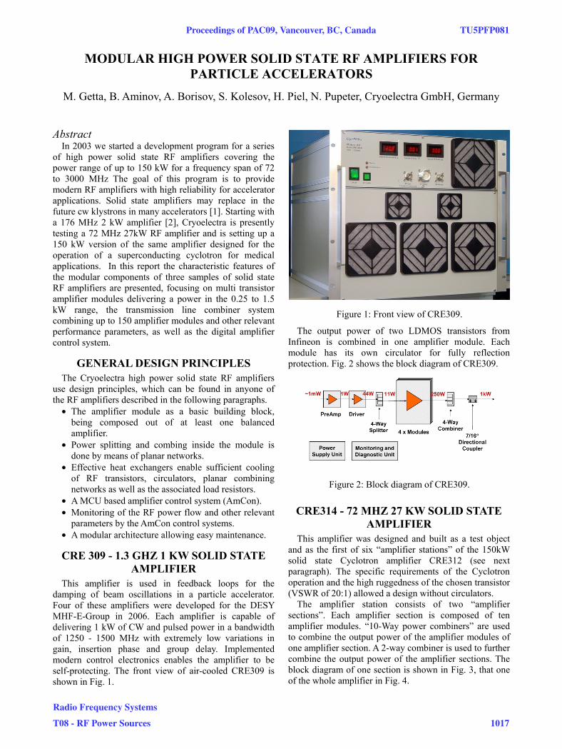
This amplifier is used in feedback loops for the damping of beam oscillations in a particle accelerator. Four of these amplifiers were developed for the DESY MHF-E-Group in 2006. Each amplifier is capable of delivering 1 kW of CW and pulsed power in a bandwidth of 1250 - 1500 MHz with extremely low variations in gain, insertion phase and group delay. Implemented modern control electronics enables the amplifier to be self-protecting. The front view of air-cooled CRE309 is shown in Fig. 1.
Figure 1: Front view of CRE309.
The output power of two LDMOS transistors from Infineon is combined in one amplifier module. Each module has its own circulator for fully reflection protection. Fig. 2 shows the block diagram of CRE309.
Figure 2: Block diagram of CRE309.
CRE314 - 72 MHZ 27 KW SOLID STATE AMPLIFIER
This amplifier was designed and built as a test object and as the first of six “amplifier stations” of the 150kW solid state Cyclotron amplifier CRE312 (see next paragraph). The specific requirements of the Cyclotron operation and the high ruggedness of the chosen transistor (VSWR of 20:1) allowed a design without circulators.
The amplifier station consists of two “amplifier sections”. Each amplifier section is composed of ten amplifier modules. “10-Way power combiners” are used to combine the output power of the amplifier modules of one amplifier section. A 2-way combiner is used to further combine the output power of the amplifier sections. The block diagram of one section is shown in Fig. 3, that one of the whole amplifier in Fig. 4.
Proceedings of PAC09, Vancouver, BC, Canada TU5PFP081
Radio Frequency Systems
T08 - RF Power Sources 1017
Figure 3: Block diagram of one amplifier section.
Figure 4: Block diagram of CRE314.
Each amplifier module contains four VDMOS transistors, each delivering about 400 W at P1. This results in a module output power of about 1.45 kW at P1. The combination is done by means of two Hybrid Couplers and a Wilkinson Combiner. A multilayer approach is used for this combining and also for the splitting network.
The DC side of the module contains four DC/DC converters which individually supply the four transistors. Each DC/DC converter has its own carrier board to enable a drain current limitation function and the monitoring of the drain currents. Fig. 5 shows the RF and the DC side of the 72 MHz amplifier module.
Figure 5: RF side (left picture) and DC side (right picture) of the 72 MHz ampifier module.
An additional interface board facilitates the communication with the Micro-Controller-Unit based amplifier control system (AmCon) as well as it measures
the forward and reflected power and the inlet and outlet temperature of the RF Amplifier Module. The control system monitors:
• Drain current of each transistor, • Forward and reflected RF power at the output of
each Amplifier Module (1.45 kW), • Inlet and outlet water temperature of each module, • Input power of the Amplifier Station, • Forward and reflected RF power at the output of the
two Amplifier Sections (14 kW), • Forward and reflected RF power at the output of the
Amplifier Station (27 kW).
The control system protects the amplifier and the load in failure cases. Fig. 6 shows the amplifier connected to a dummy-load during the site-acceptance test.
Figure 6: CRE314 at the site-acceptance test.
CRE312 - 72 MHZ 150 KW SOLID STATE CYCLOTRON AMPLIFIER
This amplifier was developed for Varian Medical Systems to drive a superconducting four sector cyclotron, to be used in a four Gantry Proton Therapy Centre like described in ref. [3]. Due to the very high financial losses in case of non-availability of the Proton Therapy Centre, the 150 kW amplifier is designed for maximum reliability and redundancy, simplicity of maintenance, early indication of degradation and fast repair in case of failure by minor trained maintenance staff.
In the 150 kW amplifier six 27 kW amplifier stations (CRE314) are being combined to deliver 150 kW of cw and pulsed power with sufficient redundancy (For block diagram see Fig. 7). Six amplifier sections (upper parts of the amplifier stations) are combined using a 6-way combiner (see Fig. 8). Another six amplifier sections (lower parts of the amplifier stations) are combined using the second 6-way combiner. Finally the upper and lower parts of the amplifier are combined by a 2-way combiner. The top view of the layout of CRE312 is given in Fig. 9. The first amplifier of this kind is going to be delivered to ACCEL in June 2009.
TU5PFP081 Proceedings of PAC09, Vancouver, BC, Canada
This 30 kW amplifier will be used to drive the second storage ring cavity for the Siam Photon Source, a 1.2 GeV synchrotron light source in Thailand [4]. CRE317 will have 32 Sub-Modules, each containing two 500 W LDMOS transistors from NXP. This leads to a Sub-Module output power of about 1 kW at P1. Each transistor will be supplied by a 1000 W AC/DC converter.
The Sub-Module is fully reflection protected by means of a circulator. Two Sub-Modules share a common water-cooler and RF-DC/DC-housing. Fig. 10 shows the block diagram of the full 118 MHz 30 kW amplifier. Currently the production of the Sub-Modules and the coaxial power combiners has started. The complete system will be operable by the end of 2009.
Figure 10: Block diagram of CRE317.
SUMMARY AND OUTLOOK Three samples of modular high power solid state RF
amplifiers with centre frequencies of 72 MHz, 118 MHz and 1.3 GHz have been introduced. The modular design will allow the combination to RF power levels of more than 100 kW.
A further RF amplifier family for 3 GHz and an output power starting from 0.5 kW is currently under design.
REFERENCES [1] P. Marchand et al., “Operation of the Soleil RF
Systems”, PAC’07, Albuquerque, 2007. [2] C. Piel et al., “Development of a Solid State RF
Amplifier in the kW Regime for Application with Low Beta Superconducting RF Cavities”, PAC’05, Knoxville, 2005.
[3] A.E. Geisler et al., “Commissioning of the ACCEL 250 MeV Proton Cyclotron”, Cyclotrons’07, Giardini-Naxos, 2007.
[4] P. Klysubun et al., “Present Status of the Siam Photon Source”, EPAC’08, Genoa, 2008.
Proceedings of PAC09, Vancouver, BC, Canada TU5PFP081