72
Modular Hydrogen Fueling Station A Design Report Submitted to the H2-Refuel Competition
| Date post: | 24-Jun-2018 |
| Category: |
Documents |
| Upload: | truongtuyen |
| View: | 216 times |
| Download: | 0 times |
Modular Hydrogen Fueling Station
A Design Report Submitted to the H2-Refuel Competition

Official Team Members: Eli Shoemake, Ian Richardson, Brian Karlberg, Derek Johnson, Greg Wallace, Nolan Beal, Carl Mayer, Steven Bell, Andrew Raub, Will Wilber, Scott Bredberg, Johnny
Wang, Dr. Jacob Leachman
Public Summary The future of hydrogen fueling is distributed. We believe, like the personal computer, hydrogen fueling will be expedited by the rapid adaptation and interoperability enabled by a modular hardware architecture. Our design for the community-centered hydrogen refueling station is fully modular in production, and use. The end result is a station flexible to hydrogen source, location, customer desired output, and future technology advances.
Our station design is uniquely capable of this modular future through the combination of two revolutionary technological advances:
1. Low-cost hydrogen liquefaction via the patent-pending Heisenberg Vortex. 2. The cryogenic thermal compression process at the heart of the winning Washington
State University fueling station design for the 2014 Hydrogen Student Competition. Instead of requiring 10,000 psi compression, our compressor uses only 200 psi to drive our Heisenberg Vortex for liquefaction. Liquid hydrogen is nearly twice the density of 700 bar gaseous hydrogen and is the most economical high-density storage option. Sealing the liquid hydrogen in a cryogenic compatible pressure vessel and allowing the hydrogen to boil causes the pressure to rise over 1000 bar, more than suitable for refueling vehicles. Simple modifications allow for direct liquid hydrogen dispensing.
We utilize the low-cost modularity of recycled shipping containers. The resulting portable station can be filled on-site or at a regional green-hydrogen supply center and transported to a local community fueling site. These portable stations can be manufactured, upgraded, repaired, and replaced in regional service facilities to minimize station down-time. This community approach maximizes the rapid-refueling value of hydrogen while minimizing capital cost to

individuals. Towards this end we’ve founded a startup company, Protium Innovations LLC, to commercialize the technology.
Our mission is to develop the first hydrogen fueling station in Washington State. We’re supported by WSU alumni and donors, the M.J. Murdock Charitable Trust, and the Washington Research Foundation.
Richardson, Ian, et al. 2014 Hydrogen Student Design Contest - Drop in Hydrogen Refueling Station. Washington State University, 2014.
Richardson, Ian, et al. 2014 Hydrogen Student Design Contest - Drop in Hydrogen Refueling Station. Washington State University, 2014.

Table of Contents
Technical Information Safety Plan and Hazard Analysis
Usability System Operation/Training Project Schedule and System Model
Installation Site
System Model Pathway to Commercialization System Cost
H2-Refuel Sponsors

Hydrogen Source
Heat Exchanger
LN2 Cycle
Pre-Cooling
Container Vortex Tube
Compressor
Storage Sensing and PLCS User Interface
Technical Information
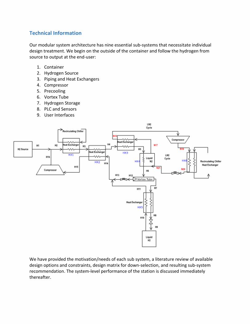
Our modular system architecture has nine essential sub-systems that necessitate individual design treatment. We begin on the outside of the container and follow the hydrogen from source to output at the end-user:
1. Container 2. Hydrogen Source 3. Piping and Heat Exchangers 4. Compressor 5. Precooling 6. Vortex Tube 7. Hydrogen Storage 8. PLC and Sensors 9. User Interfaces
We have provided the motivation/needs of each sub system, a literature review of available design options and constraints, design matrix for down-selection, and resulting sub-system recommendation. The system-level performance of the station is discussed immediately thereafter.

1. Container
From left to right: Kevin Moseley – Tim Pizzino – Mario Reillo – Nolan Beal – Scott Bredberg
Our method of using portable shipping containers to house our hydrogen fueling station lends a new level of modularity to hydrogen fueling that has never been seen before. This modularity will give us the unmatched ability to drag and drop our fueling stations to any location based on customer needs or desires. By evolving the concept of what a mobile hydrogen station can be, we have created a paradigm shift in the modularity and mobility of hydrogen fueling.
Input: Raw Syngas/Hydrogen Source
Output: Liquid Hydrogen
Musts: ● Fit all necessary components ● Securely mount all components in place for transport ● Be able to transport to competition location and any permanent location ● Meet all DOT regulations ● Meet all regulations for the shielding for a hydrogen liquefaction system ● Protect the container from both weather and vandals
Shoulds: ● Provide exterior lighting for the outside of the container ● Cosmetically look like a fueling station ● Be securely mounted in a permanent location
Background
Types of Containers Available:
Standard Steel Container: Double doors on each end, or doors over the entire length of one side, Vary in size from 10 ft to 53 ft in length, standard sizes being 20 ft and 40 ft and heights of 8ft, easy to repair, susceptible to corrosion

Ventilated Containers: Base of a Steel Container, ventilation slots in the top and bottom of the side rails, opening does not allow rain or spray to enter the container
Insulated and Refrigerated Container: Mainly available in 20 ft and 40 ft length sizes, contains an integrated refrigeration system, ensures circulation of cold air, insulated for maximum efficiency

Hard Top Container:Made of corrugated steel and available at all standard sizes, Roof and end of the container are removable
Bulk Containers: Contains roof hatches for loading, made for holding bulk cargo such as biomass/foodstuffs, equipped with forklift pockets for lifting.

LAMS (Light Air Mobile Shelter): 15ft aluminum container, 3PH and 20KW power generator, lower load capacity.
Design Specification
Container Option Specifications
A House of Quality ranks the relationship between system requirements and design alternatives. As we have researched and developed our system these relationships helped us optimize our design. The vertical axis consists of system requirements, measureable qualities that are most relevant to our design. The horizontal axis displays design alternatives. From this chart we are able to compare how each design alternative relates to the system requirements and select the best option.
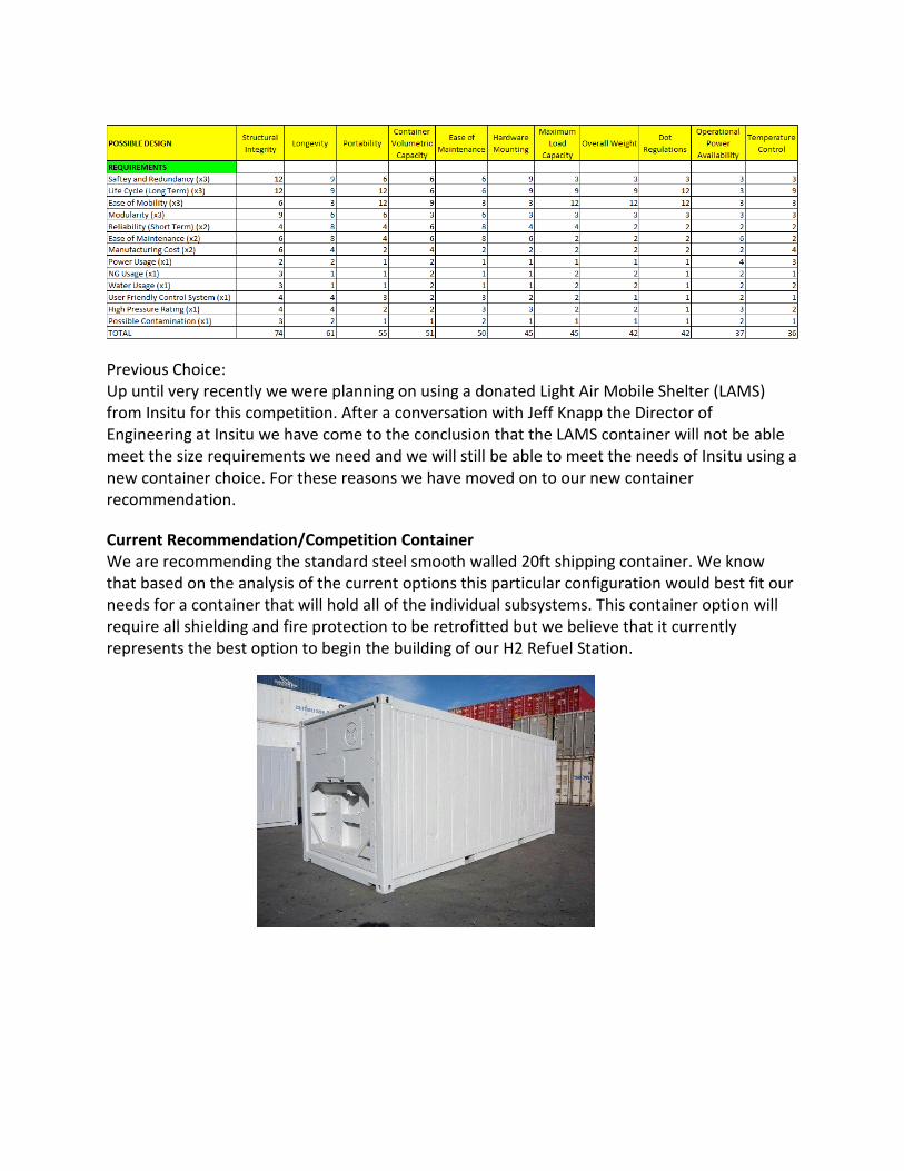
Previous Choice: Up until very recently we were planning on using a donated Light Air Mobile Shelter (LAMS) from Insitu for this competition. After a conversation with Jeff Knapp the Director of Engineering at Insitu we have come to the conclusion that the LAMS container will not be able meet the size requirements we need and we will still be able to meet the needs of Insitu using a new container choice. For these reasons we have moved on to our new container recommendation.
Current Recommendation/Competition Container
We are recommending the standard steel smooth walled 20ft shipping container. We know that based on the analysis of the current options this particular configuration would best fit our needs for a container that will hold all of the individual subsystems. This container option will require all shielding and fire protection to be retrofitted but we believe that it currently represents the best option to begin the building of our H2 Refuel Station.

2. Hydrogen Source
Top Row (From left to right): Ryan Brown, Ryan Whitehead, Paul Flerchinger, Zachary Gilvey, Derek Johnson
Bottom Row: Avery Scott, Bailee DePhelps, Ashley Vu, Daniel Barnes, Ryan Fish, David Lopez-Nava
Objective
As the Hydrogen Source, we need to create a system that separates hydrogen from water or methane. The two most promising methods currently available include steam methane reforming and electrolysis. Our subsystem is vital because we provide the gaseous hydrogen to be processed by the rest of the system. Thus, if our process doesn’t work, the whole system is unable to produce a working product. Input:
● Methane ● Water ● Electricity
Output: ● Gaseous Hydrogen and Waste Gases
Musts: ● Convert Methane/Water into Hydrogen ● Reach a purity of 99.995% or greater.
Shoulds: ● Generate Power ● Output at as high of a pressure as feasible
Background
Electrolysis: Electricity flows through a positive and negative electrode. The hydrogen and oxygen ions in the water flow to the oppositely charged electrode where hydrogen and oxygen bubbles float to the surface.
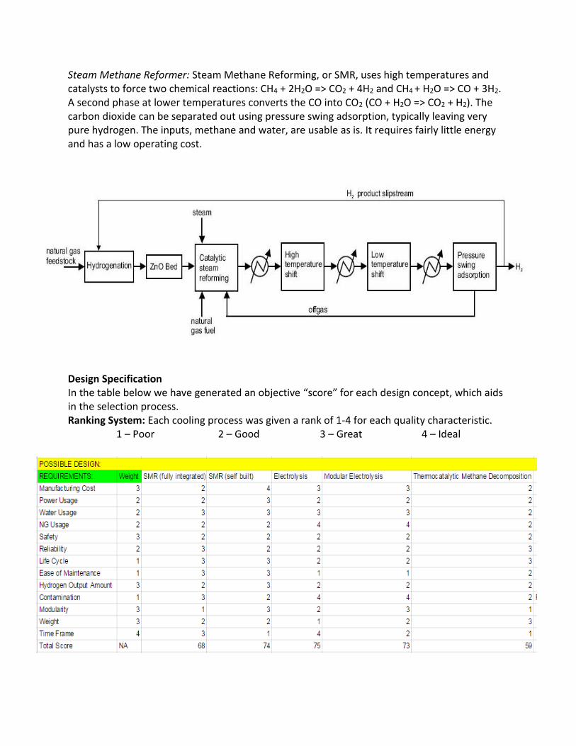
Steam Methane Reformer: Steam Methane Reforming, or SMR, uses high temperatures and catalysts to force two chemical reactions: CH4 + 2H2O => CO2 + 4H2 and CH4 + H2O => CO + 3H2. A second phase at lower temperatures converts the CO into CO2 (CO + H2O => CO2 + H2). The carbon dioxide can be separated out using pressure swing adsorption, typically leaving very pure hydrogen. The inputs, methane and water, are usable as is. It requires fairly little energy and has a low operating cost.
Design Specification
In the table below we have generated an objective “score” for each design concept, which aids in the selection process. Ranking System: Each cooling process was given a rank of 1-4 for each quality characteristic.
1 – Poor 2 – Good 3 – Great 4 – Ideal
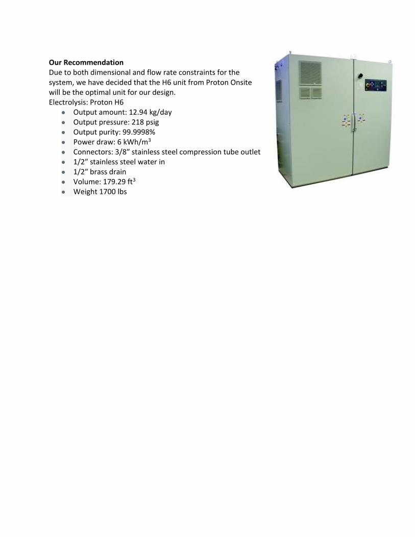
Our Recommendation
Due to both dimensional and flow rate constraints for the system, we have decided that the H6 unit from Proton Onsite will be the optimal unit for our design. Electrolysis: Proton H6
● Output amount: 12.94 kg/day ● Output pressure: 218 psig ● Output purity: 99.9998% ● Power draw: 6 kWh/m3 ● Connectors: 3/8″ stainless steel compression tube outlet ● 1/2″ stainless steel water in ● 1/2″ brass drain ● Volume: 179.29 ft3 ● Weight 1700 lbs

3. Piping and Heat Exchanger
Team Members (from left to right) Ibrahim Alazri, Brett Love, Wyatt Linville, Malcolm Wynn, Daniel Pollastro
Objective
The objective is to design the piping and heat exchangers that will be in our station. Below are the requirements and goals we are addressing:
● Input: Hot hydrogen and cold nitrogen ● Output: Cold hydrogen and hot nitrogen ● Musts:
○ Control temperatures of the nitrogen and hydrogen ○ Proper piping between the subsystems as well as inlet and exit plumbing ○ Safety shutoffs and relief valves
● Shoulds: ○ Exchangers should be as efficient as possible ○ Cost effective ○ Ease of install and maintenance ○ Standardized fittings ○ Standard valves and pipe sizes to ease repair ○ Insulate liquefied or high temperature plumbing and valves to prevent injury
Background
Piping
The materials that we have to use for piping are stainless steel or copper. Stainless steel can withstand higher temperatures and pressures with a thinner wall thickness compared to copper. Also, stainless steel has a lower heat transfer coefficient and is not affected by hydrogen embrittlement while copper is. However, stainless steel has a high cost and is more difficult to plumb while copper has a lower cost and is easier to produce.

Fittings
The fittings will be interconnecting the different sections of the system together. The different options that we have to choose from are compression, VCR, and welded fittings. The compression fitting works the best with a modular design, they are easy to install and maintain, and make it easy to integrate sensors. The downfalls to compression fittings are non-zero clearance and there is a greater risk for contamination. The VCR fittings do have zero clearance and are good for modular design as well, but are easily damaged and have a high installation cost. The final option is to use welded joints which have the lowest cost. These joints also have the best longevity and have an ideal seal. The problems with welded joints for our system is that they are not modular and not easily serviced.
VCR Compression Welded
Heat Exchangers
Tube and shell heat exchangers and plate type heat exchangers are the two types that we have available. The tube and shell has a lower cost with higher working temperatures and pressures when compared to the plate type. Also, tube and shell heat exchangers will have a lower pressure drop across the tube cooler, are easy to build, and leaks are easy to find and repair. Unfortunately there is a lower heat transfer efficiency, and the cleaning and maintenance requires enough clearance to remove the tube nest. The plate type heat exchanger is smaller in size, easier to clean and maintain, and has high efficiency. However, there is a higher initial cost compared to tube and shell, leaks are difficult to find, and bonding material between plates limits operating temperature.

Tube and Shell Plate Type
Customer Requirements: ● Safety regulations ● Reliability ● Low manufacturing costs
Key Characteristics: ● Ease of Maintenance ● Weight and size
Ranking System: Each cooling process was given a rank of 1-4 for each quality characteristic. 1 – Poor 2 – Good 3 – Great 4 – Ideal
Recommendations
We recommend the use of stainless steel for piping. Lower costs of operation, less heat loss, and a higher longevity in cyclic environmental loading capability is why stainless steel is the preferred material.

We are choosing to use both exchanger types. Some areas require low pressures and low temperature differentials in which case a plate type is preferred. In high temperature and pressure differentials a tube and shell is preferred. Due to the desire for a modular design we are choosing to use Swagelok Compression Fittings. These give us all around reliability, cost benefit, and ease of maintenance.
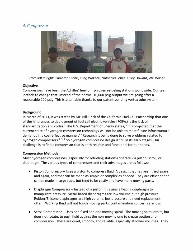
4. Compressor
From left to right: Cameron Stone, Greg Wallace, Nathaniel Jones, Riley Howard, Will Wilber
Objective Compressors have been the Achilles’ heel of hydrogen refueling stations worldwide. Our team intends to change that. Instead of the normal 10,000 psig output we are going after a reasonable 200 psig. This is attainable thanks to our patent-pending vortex tube system.
Background
In March of 2013, it was stated by Mr. Bill Elrick of the California Fuel Cell Partnership that one of the hindrances to deployment of fuel cell electric vehicles (FCEVs) is the lack of standardization and codes.1 The U.S. Department of Energy states, “It is projected that the current state of hydrogen compressor technology will not be able to meet future infrastructure demands in a cost-effective manner.”2 Research is being done to solve problems related to hydrogen compressors.2, 3, 4 So hydrogen compressor design is still in its early stages. Our challenge is to find a compressor that is both reliable and functional for our needs.
Compression Methods
Most hydrogen compressors (especially for refueling stations) operate via piston, scroll, or diaphragm. The various types of compressors and their advantages are as follows:
● Piston Compressor– Uses a piston to compress fluid. A design that has been tried again and again, and that can be made as simple or complex as needed. They are efficient and can be made in large sizes, but tend to be costly and have many moving parts.
● Diaphragm Compressor – Instead of a piston, this uses a flexing diaphragm to manipulate pressure. Metal-based diaphragms are low volume but high pressure. Rubber/Silicone diaphragms are high volume, low pressure and need replacement often. Working fluid will not touch moving parts, contamination concerns are low.
● Scroll Compressor – Uses one fixed and one moving spiral. The moving spiral orbits, but does not rotate, to push fluid against the non-moving one to create suction and compression. These are quiet, smooth, and reliable, especially at lower volumes. They

have fewer moving parts but are highly susceptible to debris (which should not be present in our system).
Scroll Compressor Cycle of Operation
● Ionic Liquid Piston Compressor – Acts similarly to piston compressor, but uses an ionic liquid rather than a metal piston. These have very few parts and are long lasting. Produces very little waste heat.
● Electrochemical hydrogen compressor – Uses electricity to separate hydrogen into protons and electrons and force them across a membrane. Can maintain high pressure, is compact, uses no moving parts, and has good efficiency.
● Hydride Compressor – Absorbs hydrogen ions at low temperature and pressure and expels them at high pressure when heated. High volume flow rate with no moving parts, but expensive and heavy and produce waste heat.
Since we will not have the time or funding to create a compressor from scratch, we are limited to the already established methods of compression: piston, scroll, or diaphragm. The most efficient method in obtaining a compressor for our system in this case is to choose a pre-developed compressor from a company that specializes in making them and work with a representative to meet as many of our design specifications as possible. Design Specifications
The compressor takes in hydrogen from two components: the “hot” gas expelled from the vortex tube and excess hydrogen from the storage tank. This injects the hydrogen back into the pre-cooling cycle and the vortex tube where it will be liquefied and then stored. To maximize system efficiency, the following is required of our compressor:
● 200 psi output pressure: The vortex tube requires a certain amount of pressure to operate at its highest efficiency. When the gas enters, it is forced into a spiral at high speeds. This high speed cannot be achieved without high pressure forcing it through the device. By calculating the ideal pressure for the vortex tube, we arrive at needing compression of approximately 200 psi.
● 1.5-5 g/s mass flow rate: Based on the proportion of hydrogen expelled by the vortex tube’s “hot” end compared to its input, our return loop will need to move approximately 1.5-5 g/s of hydrogen total.
● Oil-Free: To ensure that no lubricants or oils leach into the hydrogen, we will use a compressor that uses no oil in the working space.
● Inexpensive: Funds are limited. The source and purification teams alone are expected to take up to half the budget.

● Dependable: Any time spent out of commission is money lost. The H2 Refuel Prize desires a system able to operate for 98% of the time.
● Compact: The entire space of the container is only about 600 cubic feet. The storage and the source groups are expected to take up about 400 cubic feet combined.
Above is our house of quality that relates requirements to different design alternatives.
Recommended:
1. RIX 4VX (3 g/s) ● Piston type ● 200 psig discharge ● 3 g/s (259.2 kg/day) flowrate ● 30 Hp ● 5-6 months lead time ● Oil-Free ● Designed for hydrogen ● Air-Cooled ● Size: 54″W x 27″L by 33″H ● Weight: 750 lb ● Quoted at $130,000
2. RIX 4VX (5 g/s) ● Piston type ● 200 psig discharge ● 5 g/s (432 kg/day) flowrate ● 35 Hp ● 5-6 months lead time ● Oil-Free ● Designed for hydrogen ● Air-Cooled ● Size: 54″W x 27″L by 33″H
● Weight: 750 lb ● Quoted at $140,000
We intend to use the 3 g/s (259.2 kg/day) system because when combined with the output of the electrolyzer it produces optimal hydrogen flow into the vortex tube, about 3.6 g/s. We also will choose a model that expels hydrogen at a pressure of 200 psig. This pressure is equivalent to the hydrogen exiting the electrolyzer and is the lower limit of usable pressure across the vortex tube.
The 4VX (3 g/s) model requires maintenance breaks every 6000-8000 hours depending on use. These maintenance breaks will cost around $15,000 and take a trained technician 6-8 hours to complete. This includes replacing piston rings, rider bands, reed valves (suction & discharge), gas packing seals, and oil wiper seals. The compressor’s lifetime is over ten years if maintained properly.
In essence, we need to acquire a high quality compressor to move the hydrogen along it’s path efficiently. In doing this, we can achieve the goals of the H2 design competition and create a working hydrogen refueling station.
With the hydrogen sufficiently compressed and the gas flowing as needed, it can finally move on to the next stages. All the output of the compressor will next go through a heat exchanger system to remove excess heat and then move on to the pre-cooling system.

5. Precooling
Left to right: Jordan DeGroot, Gerardo Perez, Neil Baldwin, Usama Al Ramadhani, Al-Harith Al
Harthy, Chandler Luke
Objective
The pre-cooling team will design a way to cool the hot, gaseous hydrogen down to a
temperature appropriate enough to be turned into liquid form.
Input: Gaseous hydrogen from the compressor at 200 psi and 25° C. Must: Cool hydrogen below -173° C and kept at 200 psi while maintaining safety standards. Should: Relatively low cost, cooled to a preferable -203° C, take up minimal space. Output: Gaseous hydrogen between -203° C and -173° C to the vortex tube.
Precooling system flowchart
Background
Our first challenge will be selecting the most suitable cooling process that will fulfill our objectives. The following information represents a glimpse of the background research on various cooling processes that we initially looked into for our design. Evaporation Cooling: As the name suggests, this method is based upon natural cooling via evaporation. The bodily process of sweating is the most quintessential example of this process, and the self same principle can be extended to serve evaporative coolers.
Vapor-Compression Refrigeration: A refrigeration system contains a compressor, condenser, a throttling device, and an evaporator. The system additionally includes a fluid that circuits the closed path of the system (known as the refrigerant) which was favored over water due to its lower boiling point.
Liquid Nitrogen Cooling: Cooling via liquid nitrogen presents itself as another effective solution. Liquid nitrogen can operate at cryogenic temperatures which will be able to cool the hydrogen to those temperatures.
Carbon Dioxide Cooling: Instead of using refrigerant or liquid nitrogen, CO2 is yet another option for a refrigeration cycle.
Design Specifications
In order to effectively compare the different means of cooling the gaseous hydrogen, we have thought up a list of quality characteristics that represent the ideal cooling process. From there, a table has been created in which we can rank the effectiveness of each of these quality characteristics for each possible design.
Quality Characteristics: There are the 7 quality characteristics that represent the ideal cooling process in our design. These characteristics each play a fundamental role in our design and will all be important to consider for ranking all the design possibilities. Here are the 7 quality characteristics and why they are important for this design: Safety: This is the most important characteristic because we want everybody to be safe. Engineers have a code of ethics that we abide by and that we promise to always uphold. Everything that we include in our final design will be verified for complying with the appropriate safety standards.
Cooling Efficiency: How well does this process cool the hydrogen. This is a measure of how effective the design is at completing the objective.
Manufacturing Cost: This is ranked as one of the most important characteristics because we want to make hydrogen refueling an affordable process.
Power Usage: Keeping the power usage to a minimum will allow this process to be most efficient.
Space: This will be important because the container that holds all the components that comprise the hydrogen refueling station is a certain size. Therefore, keeping our subsystem to a reasonable size will ensure that all the systems can easily fit.
Reliability: We want our design to work without fail. Ensuring that our cooling system gets the job done every single time is a characteristic of a great design.
Life Cycle: A cooling system that lasts a long time without having to replace is a great cooling system. This just makes it easier for everybody.
Ease of Maintenance: We want our cooling system to be easily accessible and repairable.

In the table below, the quality characteristics of the ideal cooling process are listed on the left column. The possible design ideas are listed on the top row.
Ranking System: Each cooling process was given a rank of 1-4 for each quality characteristic. 1 – Poor 2 – Good 3 – Great 4 – Ideal
Safety, Cooling Efficiency, and Manufacturing cost were multiplied by 3 since these quality characteristics are the most important. Power Usage, Space, Reliability were multiplied by 2 since they are moderately important. The Life Cycle and the Ease of Maintenance were the least important quality characteristics so their rows were multiplied by 1.
Findings: Based on the rubric we’ve developed, the combination of a refrigeration cycle and a liquid nitrogen bath is the best design.
Preliminary Designs
There are a few paradigms for the process of cooling hydrogen. Namely three that we will consider for our design. Option 1: Refrigeration Cycle + Liquid Nitrogen Bath
Option 2: Liquid Nitrogen Refrigeration Cycle
Option 3: Carbon Dioxide Refrigeration Cycle
Our Recommendation
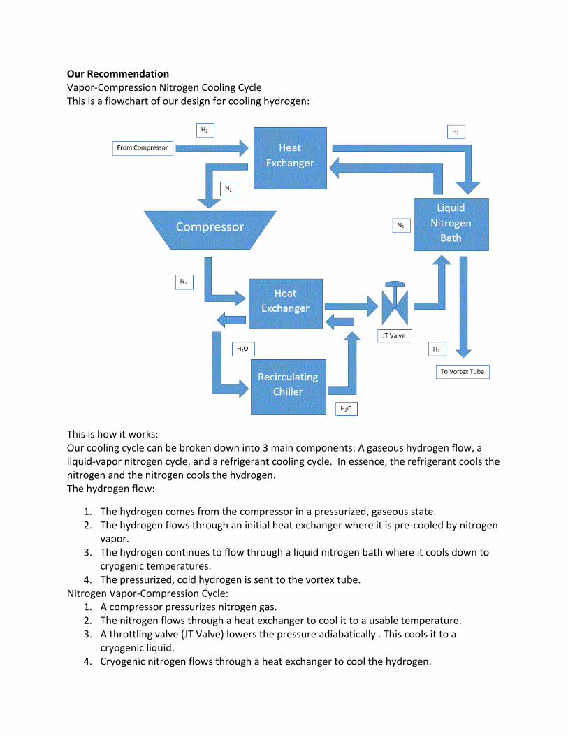
Vapor-Compression Nitrogen Cooling Cycle
This is a flowchart of our design for cooling hydrogen:
This is how it works: Our cooling cycle can be broken down into 3 main components: A gaseous hydrogen flow, a liquid-vapor nitrogen cycle, and a refrigerant cooling cycle. In essence, the refrigerant cools the nitrogen and the nitrogen cools the hydrogen. The hydrogen flow:
1. The hydrogen comes from the compressor in a pressurized, gaseous state. 2. The hydrogen flows through an initial heat exchanger where it is pre-cooled by nitrogen
vapor. 3. The hydrogen continues to flow through a liquid nitrogen bath where it cools down to
cryogenic temperatures. 4. The pressurized, cold hydrogen is sent to the vortex tube.
Nitrogen Vapor-Compression Cycle: 1. A compressor pressurizes nitrogen gas. 2. The nitrogen flows through a heat exchanger to cool it to a usable temperature. 3. A throttling valve (JT Valve) lowers the pressure adiabatically . This cools it to a
cryogenic liquid. 4. Cryogenic nitrogen flows through a heat exchanger to cool the hydrogen.
5. Heat from the hydrogen gas boils off the nitrogen into vapor form. 6. Nitrogen vapor is sent through a heat exchanger that pre-cools the hydrogen. 7. The ‘hot’ nitrogen returns to the compressor and the cycle continues.
Refrigerant Cycle: 1. Refrigerant enters a recirculating chiller and cools down. 2. The cool refrigerant enters a heat exchanger and cools the nitrogen. 3. Warm refrigerant flows out of the heat exchanger and the cycle continues.
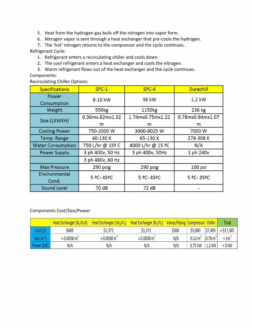
Components: Recirculating Chiller Options:
Components Cost/Size/Power
6. Vortex Tube
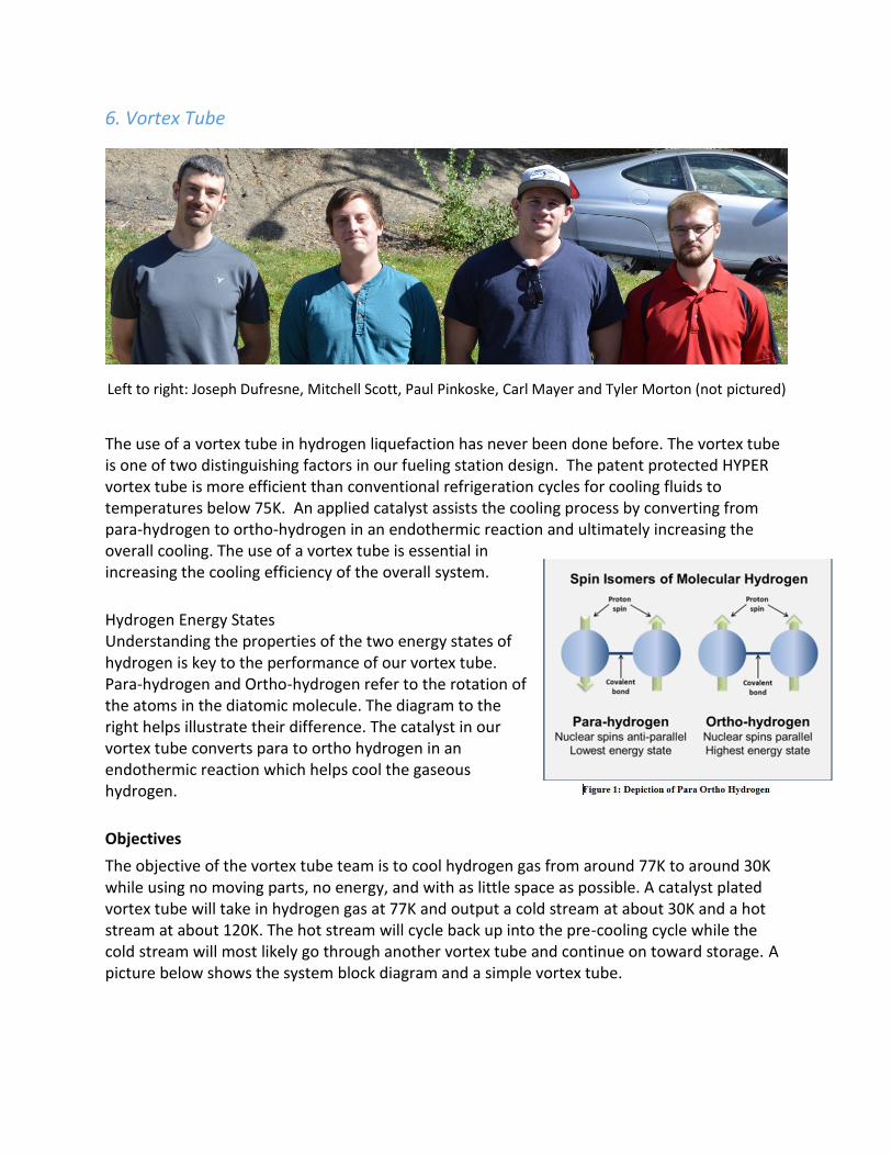
Left to right: Joseph Dufresne, Mitchell Scott, Paul Pinkoske, Carl Mayer and Tyler Morton (not pictured)
The use of a vortex tube in hydrogen liquefaction has never been done before. The vortex tube is one of two distinguishing factors in our fueling station design. The patent protected HYPER vortex tube is more efficient than conventional refrigeration cycles for cooling fluids to temperatures below 75K. An applied catalyst assists the cooling process by converting from para-hydrogen to ortho-hydrogen in an endothermic reaction and ultimately increasing the overall cooling. The use of a vortex tube is essential in increasing the cooling efficiency of the overall system.
Hydrogen Energy States Understanding the properties of the two energy states of hydrogen is key to the performance of our vortex tube. Para-hydrogen and Ortho-hydrogen refer to the rotation of the atoms in the diatomic molecule. The diagram to the right helps illustrate their difference. The catalyst in our vortex tube converts para to ortho hydrogen in an endothermic reaction which helps cool the gaseous hydrogen.
Objectives The objective of the vortex tube team is to cool hydrogen gas from around 77K to around 30K while using no moving parts, no energy, and with as little space as possible. A catalyst plated vortex tube will take in hydrogen gas at 77K and output a cold stream at about 30K and a hot stream at about 120K. The hot stream will cycle back up into the pre-cooling cycle while the cold stream will most likely go through another vortex tube and continue on toward storage. A picture below shows the system block diagram and a simple vortex tube.

Input:
● H2 gas @77 K, 200 psi ● 50/50 % Ortho-Para ● 0.15 g/s
Must: ● Accept H2 at 0.15 g/s ● Separate hot (Ortho) and cold (Para) H2 ● Collect H2 at ~30 K ● Recycle H2 at ~120 K
Output 1: ● Hydrogen gas ~30 K and 14 psi ● 25/75 % Ortho-Para
Output 2: ● Hydrogen gas ~120 K and 14 psi ● 75/25 % Ortho-Para
Background There are many changes that can be made to a vortex tube to control its performance. Below is a summary of these changes and how they affect the vortex tube:
Parallel flow vs. Counterflow: ● Parallel flow – A parallel flow vortex tube has a hole in the throttle valve at the end so
the cold stream and the hot stream can exit at the same side (picture below).
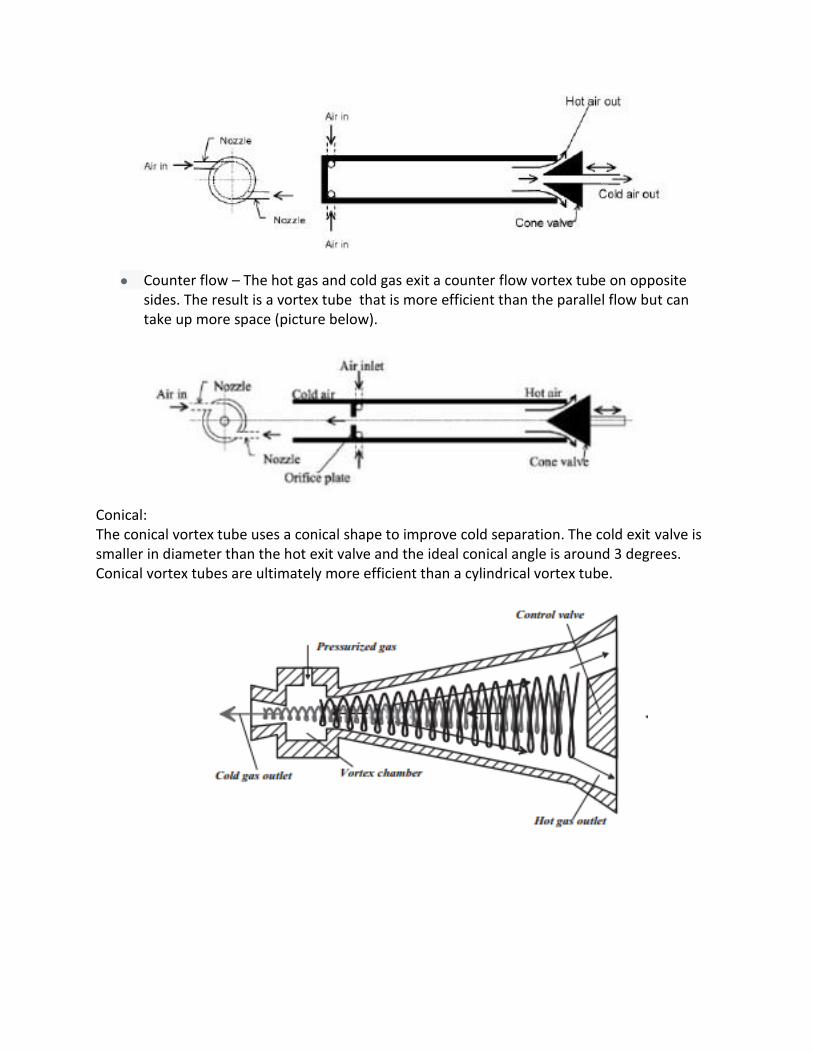
● Counter flow – The hot gas and cold gas exit a counter flow vortex tube on opposite
sides. The result is a vortex tube that is more efficient than the parallel flow but can take up more space (picture below).
Conical: The conical vortex tube uses a conical shape to improve cold separation. The cold exit valve is smaller in diameter than the hot exit valve and the ideal conical angle is around 3 degrees. Conical vortex tubes are ultimately more efficient than a cylindrical vortex tube.

Rifled: Rifling on the inside of the vortex tube works much like it does in a rifle. The rifling along the tube will assist in the vorticity of the gas. The application of rifling may also create a greater endothermic reaction from the catalyst.
Plenum Designs: These designs vary the number of ports and the angles at which they inject gas into the tube. Below are two examples of plenum chambers.
Cascading: The use of multiple vortex tubes in series to increase the cooling effect Non-adiabatic: A non-adiabatic vortex tube has no insulation. In this configuration it would be possible to use the tube itself as a section of a heat exchanger. Variable flow: Changing the input and output flows allows for optimization of the vortex tube in terms of flow rate.
Design Specification Based on all of these different design parameters we made a house of quality to quantitatively show how each design compares to each other. Using this, the vortex tube team has come to a conclusion on the optimal design of a vortex tube.

Ranking System: Each cooling process was given a rank of 1-4 for each quality characteristic. 1 – Poor 2 – Good 3 – Great 4 – Ideal
The requirements are weighted based on their importance in the final design. This weight system insures the less important qualities of a design cannot over power the more important qualities in the design thus providing an accurate representation of the best options. Below are listed what our house of quality show to be the best design parameters.
Optimal Vortex Tube Design Parameters
● Conical Tube Shape ○ More efficient than a linear tube ○ Greater temperature difference between hot and cold
● Plenum Chamber with 6 inlets ○ Increases inlets without increasing external piping ○ More inlets generates a better vortex
● Counter Flow Outlets ○ Greater cold fraction ○ Assists in the vorticity of the tube
Through our research we have realized that there currently is not a commercial vortex tube that perfectly fits our needs. No vortex tubes on the market are designed for gaseous hydrogen at very low temperatures. Most vortex tubes are also very basic in their design. Now that we have optimized our design parameters we will be working with a Washington State University machine shop to create our ideal vortex tube.

7. Hydrogen Storage
Team members (left to right): Shaoyung Sun, Edward Lie, Taylor Bryant, Dylan Fitzgerald, Toan Luu
We are building on and improving the design of the 2014 Hydrogen Education Foundation design contest winners for the Department of Energy’s H2-refuel prize competition. Washington State University was the winner of this competition and we have a provisional patent for a type IV polymer liner. Welcome to the H2 Storage section.
● Input: Liquid hydrogen at 20 K (-423.67 F) and 344.7 kPa (50 psi) ● Output: Gaseous hydrogen at 233 K (-40.27 F) and 89.63 – 117.2 MPa (13 – 17
kpsi)Q
Basic flow-chart describing transfer of liquid hydrogen to liquid tank and dispensing tanks.
● Musts: ○ Meet all applicable standards for competition and safety ○ Store hydrogen in liquid form until it is needed in the dispensing tank
● Shoulds: ○ Provide temperature and pressure feedback data ○ Relieve pressure as needed to prevent failure ○ Automatically transfer hydrogen from the liquid tank to the dispensing tank
Background
Currently there exists five types of tanks that are used to store hydrogen. These tanks are classified under type I, II, III, IV, and V where the latter types usually have higher pressure ratings. Chemical storage is not considered as an option for this competition due to economic restrictions and its current technical underdevelopment.
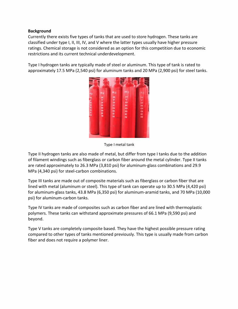
Type I hydrogen tanks are typically made of steel or aluminum. This type of tank is rated to approximately 17.5 MPa (2,540 psi) for aluminum tanks and 20 MPa (2,900 psi) for steel tanks.
Type I metal tank
Type II hydrogen tanks are also made of metal, but differ from type I tanks due to the addition of filament windings such as fiberglass or carbon fiber around the metal cylinder. Type II tanks are rated approximately to 26.3 MPa (3,810 psi) for aluminum-glass combinations and 29.9 MPa (4,340 psi) for steel-carbon combinations.
Type III tanks are made out of composite materials such as fiberglass or carbon fiber that are lined with metal (aluminum or steel). This type of tank can operate up to 30.5 MPa (4,420 psi) for aluminum-glass tanks, 43.8 MPa (6,350 psi) for aluminum-aramid tanks, and 70 MPa (10,000 psi) for aluminum-carbon tanks.
Type IV tanks are made of composites such as carbon fiber and are lined with thermoplastic polymers. These tanks can withstand approximate pressures of 66.1 MPa (9,590 psi) and beyond.
Type V tanks are completely composite based. They have the highest possible pressure rating compared to other types of tanks mentioned previously. This type is usually made from carbon fiber and does not require a polymer liner.
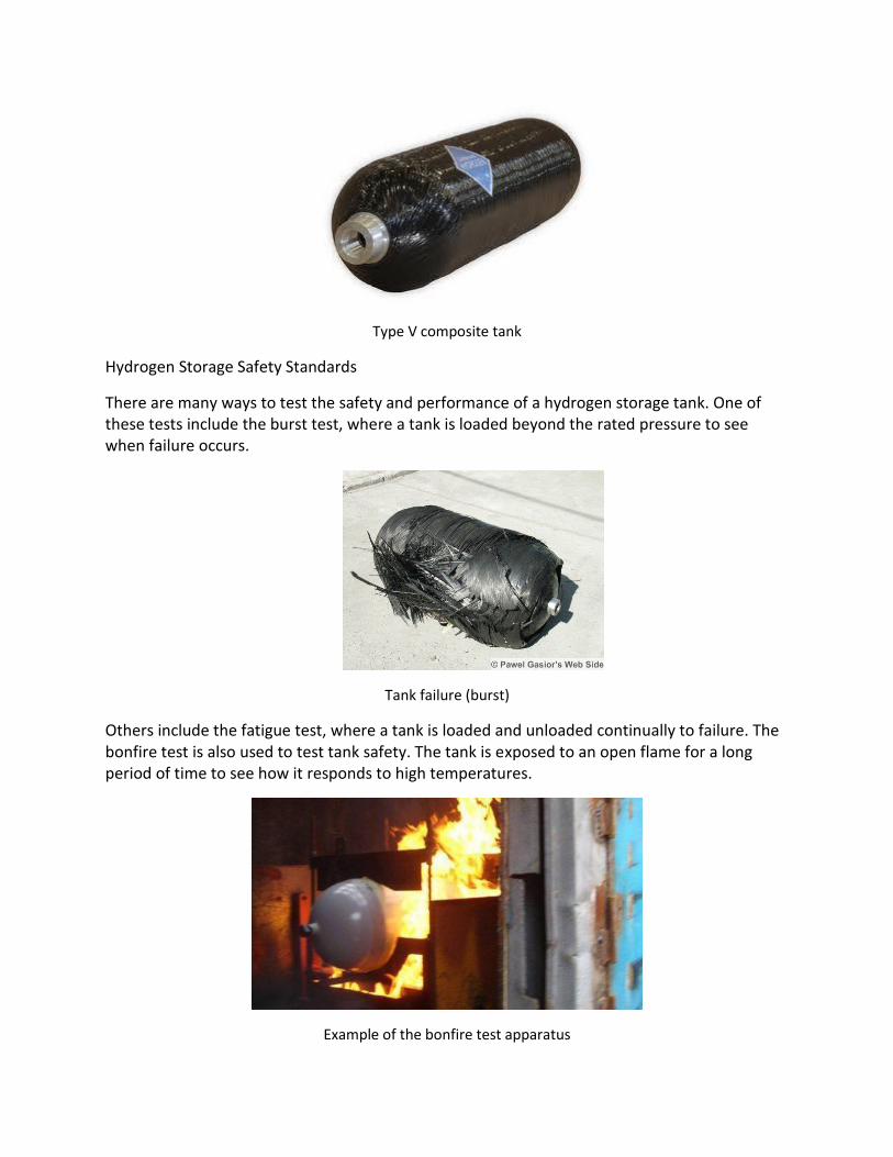
Type V composite tank
Hydrogen Storage Safety Standards
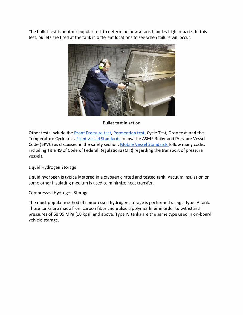
There are many ways to test the safety and performance of a hydrogen storage tank. One of these tests include the burst test, where a tank is loaded beyond the rated pressure to see when failure occurs.
Tank failure (burst)
Others include the fatigue test, where a tank is loaded and unloaded continually to failure. The bonfire test is also used to test tank safety. The tank is exposed to an open flame for a long period of time to see how it responds to high temperatures.
Example of the bonfire test apparatus
The bullet test is another popular test to determine how a tank handles high impacts. In this test, bullets are fired at the tank in different locations to see when failure will occur.
Bullet test in action
Other tests include the Proof Pressure test, Permeation test, Cycle Test, Drop test, and the Temperature Cycle test. Fixed Vessel Standards follow the ASME Boiler and Pressure Vessel Code (BPVC) as discussed in the safety section. Mobile Vessel Standards follow many codes including Title 49 of Code of Federal Regulations (CFR) regarding the transport of pressure vessels.
Liquid Hydrogen Storage
Liquid hydrogen is typically stored in a cryogenic rated and tested tank. Vacuum insulation or some other insulating medium is used to minimize heat transfer.
Compressed Hydrogen Storage
The most popular method of compressed hydrogen storage is performed using a type IV tank. These tanks are made from carbon fiber and utilize a polymer liner in order to withstand pressures of 68.95 MPa (10 kpsi) and above. Type IV tanks are the same type used in on-board vehicle storage.
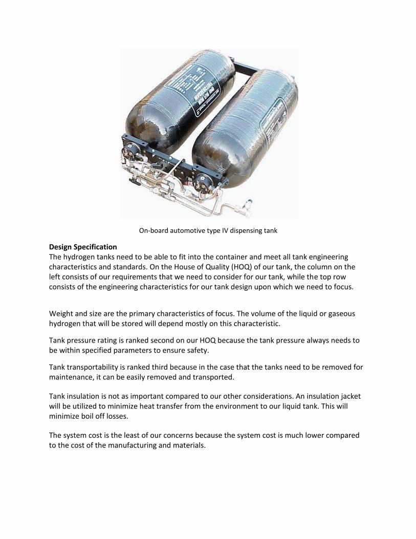
On-board automotive type IV dispensing tank
Design Specification
The hydrogen tanks need to be able to fit into the container and meet all tank engineering characteristics and standards. On the House of Quality (HOQ) of our tank, the column on the left consists of our requirements that we need to consider for our tank, while the top row consists of the engineering characteristics for our tank design upon which we need to focus.
Weight and size are the primary characteristics of focus. The volume of the liquid or gaseous hydrogen that will be stored will depend mostly on this characteristic.
Tank pressure rating is ranked second on our HOQ because the tank pressure always needs to be within specified parameters to ensure safety.
Tank transportability is ranked third because in the case that the tanks need to be removed for maintenance, it can be easily removed and transported.
Tank insulation is not as important compared to our other considerations. An insulation jacket will be utilized to minimize heat transfer from the environment to our liquid tank. This will minimize boil off losses.
The system cost is the least of our concerns because the system cost is much lower compared to the cost of the manufacturing and materials.

Above, Hydrogen Storage House of Quality
Recommended Design
Simply put, the storage tank will inject a small volume of liquid hydrogen into a cryogenic rated type IV dispensing tank. The environment will heat the hydrogen to approximately 233 Kelvin and an internal pressure of approximately 89.63 MPa (13 kpsi). Cascade Filling will be utilized to dispense liquid hydrogen into the vehicle at this point. All tanks will be equipped with an in-tank regulator monitoring internal state. WSU has a provisional patent on a cryogenic rated polymer liner for a Type IV tank. WSU will work with Tuffshell and other compatible manufacturers to create these dispensing tanks.
Above, Tuffshell type IV composite tanks
Design Details
We will use a single 750 liter (~200 gal) Cryofab liquid storage tank with an insulation jacket. Two type IV Tuffshell dispensing tanks with 60 liter (15 gal) capacity will accompany the liquid tank. This design utilizes the aforementioned provisional patented polymer liner wrapped with Tuffshell carbon fiber to achieve cryogenic rating. Tuffshell is recognized as an industry leader in the onboard automotive storage.

8. Sensing and PLCs
Team left to right: Jay Pittenger, Cody Sweat, Jake Hibbard, Christopher Marrinan, Rick Scholz
Objective
The Programmable Logic Controller (PLC) and sensor sub assembly is an electrical system designed to interface with all of the other subsystems in the design. Its purpose is to monitor and in some cases control the entire hydrogen fueling process. To do this the PLC will read data from sensors placed throughout the process then interpret this data and actuate valves and pumps. The PLC sub assembly:
Must: ● Maintain autonomous operation of the entire system through varying
environments, and operating conditions. ● Monitor critical operating levels and be able to implement appropriate shut
down procedures if something goes wrong. Should:
● Include displays for current operating levels
PLC system diagram

Background There are many major companies involved in developing PLCs to control various systems from large factories to car washes and gas stations. These give us a good reference to various PLC designs we can incorporate into our system. Many of these companies also produce different sensors for all kinds of applications, we are primarily interested in pressure/temperature transducers, and flow rate sensors. Working with liquid hydrogen, the sensors in our sub assembly will need to operate in extreme temperature and pressure environments and meet OSHA 1910.103, and NFPA 70 standards. These are safety standards for wiring and using electrical equipment with hydrogen systems.
STI dual output pressure temperature transducers and transmitters
PLCs started to take off in the early 1970s. Before PLCs, factories used elaborate circuits full of relays and timing devices to accomplish some basic control in manufacturing facilities. Early PLCs were very hard to use and needed a clean, temperature controlled space to operate. Programing early PLCs also required a trained technician. As PLCs have advanced they have become much more powerful and can withstand adverse environments. Programing software has also advanced making it much easier for anyone to use. The Siemens product line is a typical example of how companies produce several different PLCs with varying levels of complexity.

Siemens PLC products
There are 2 major types of PLCs, integrated and modular:
Integrated (basic) PLCs are pre-made with a set number of ports and computing ability. Integrated PLCs are generally for less complex systems, and offer less flexibility with a limited number of configurations.
XINJE integrated PLC
Modular (advanced) PLCs start with an empty rack and allow the user to select an appropriate CPU and signal units for the application. Modular PLCs are completely customizable, and can be used for complex applications. Modular PLCs can also be changed at any time by simply replacing different signal units without replacing the entire PLC.

Modular PLC rack and modules
Design Specifications In order to quantify our PLC design and relate it to the overall design of our hydrogen fueling station we have created a of house of quality. The major choice we had to make was whether to go with a modular or integrated type PLC. From the HOQ you can see a modular type PLC was a better design choice for our system.
Sub Assembly HOQ
Recommendation
Based on our house of quality and system requirements, we recommend using the Allen Bradley 1756, with Logix 5000 design software. The Allen Bradley 1756 can be highly customized, and has advanced features for specific data collection such as flow rate.
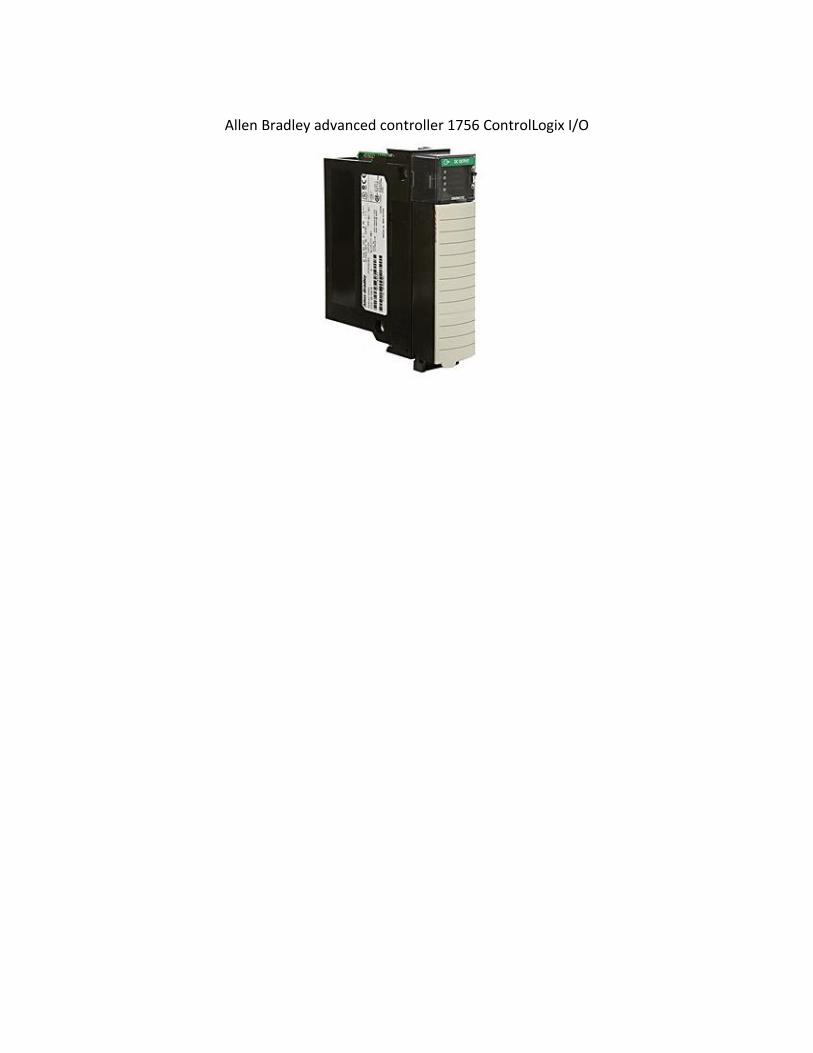
Allen Bradley advanced controller 1756 ControlLogix I/O

8. User Interfaces
Team Members (From left to right):
Tucker Stone, Michael Towne, Drew Christian, Jeff Bauer and Lachlan Sinclair
Objective
The user interface for any fueling stations needs to be safe, efficient and easy to operate. Anyone should be able to safely come up to the station and pump hydrogen fuel into their car without being confused or going through a long process. We will be making sure the system is very usable and meets the applicable safety standards while meeting our musts and shoulds.
Must: ● Fuel at pressures between 5,000 and 10,000 psi ● Safely and securely connect the station to the vehicle ● Meet SAE criteria for fueling, vehicle connection, and pump handle storage (SAE J2600,
SAE J2601, SAE J2799) ● Securely process payments ● Display information important to the consumer
Should: ● Be user friendly ● Have an appealing design ● Have high durability and resistance to weather ● Be cost effective to maintain
Background Main points from “Usability Engineering” by Jakob Nielsen that affect the User Interface:
● Less is more: giving the user every bit of information and every option can be both overwhelming and confusing. Information and options displayed need to be cut down to the essentials.
● Details matter: small details can ruin the usability of the interface if they aren’t perfect.
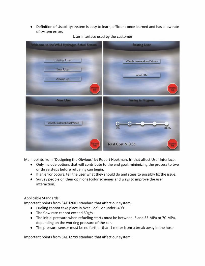
● Definition of Usability: system is easy to learn, efficient once learned and has a low rate of system errors
User Interface used by the customer
Main points from “Designing the Obvious” by Robert Hoekman, Jr. that affect User Interface: ● Only include options that will contribute to the end goal, minimizing the process to two
or three steps before refueling can begin. ● If an error occurs, tell the user what they should do and steps to possibly fix the issue. ● Survey people on their opinions (color schemes and ways to improve the user
interaction).
Applicable Standards: Important points from SAE J2601 standard that affect our system:
● Fueling cannot take place in over 122°F or under -40°F. ● The flow rate cannot exceed 60g/s. ● The initial pressure when refueling starts must be between .5 and 35 MPa or 70 MPa,
depending on the working pressure of the car. ● The pressure sensor must be no further than 1 meter from a break away in the hose.
Important points from SAE J2799 standard that affect our system:

● The nozzle will communicate with the car via an infrared signal. The data must be communicated in ASCII format.
● The nozzle shall have at least 3 infrared receivers: ○ Located 22 ±4 mm from the axis of the nozzle. ○ The external chassis of the receivers on the nozzle shall be between 15 and
35mm from the back of the car’s fitting. ● The vehicle will transmit many things to the receiver including:
○ The volume of the tank in liters and the nominal working pressure of the tank. ○ The pressure of the hydrogen in the car’s fuel tank in MPa. ○ The temperature of the gas in the fuel tank in Kelvin
Communication Flow Chart from SAE J2799
Design Specifications
For the user interface we focused our HOQ around variables such as the ease of use, customer experience, and interface installation. We weighted these variables based off factors such as manufacturing cost, life cycle, and ease of maintenance. With that we are able create relationships between the factors and variables, allowing us to analyze the potential performance of our design.

Simplified User Interface HOQ
Recommendation
After evaluating our house of quality and system requirements, we have decided to use a technologically advanced system, which consists of a WEH fueling assembly and an LG Chromebase computer incorporated with a keypad. The WEH fueling assembly is capable of dispensing Hydrogen at 10,000 psi which includes a H2 dispensing nozzle, 3 meter dispensing hose and a breakaway connection. The LG Chromebase computer is inexpensive, fulfils the requirements needed for the interface, makes it easy to input an external hard drive for maximum memory and would work well with a monitor that the user would interact with. A keypad would be used to operate the screen and get the user through the fueling process. We will house the hose on the inside of the container and make it accessible after the user has watched an instructional safety video. The safety video will show users how to properly and safely fuel their vehicle. The video can be bypassed by returning users by entering a pin they acquire after they watch the video for the first time.

9. System Level Performance
We used EES (engineering equation solver) to mathematically model our system. This program uses thermodynamic properties and conservation laws to ensure our system will function as intended. This includes energy balance equations and mass balance equations when applicable. Before finalizing our model, we developed a basic properties chart to ensure neighboring
components have compatible states as pictured below:
Component Parameters
We have chosen the respective individual components after ensuring that the thermodynamic properties of the hydrogen could be match up across interfaces. As stated above, we used EES to model our entire system and evaluate its performance as a whole. EES Solved the mass, energy, and entropy balances for all the hydrogen streams in the following flow diagram, which is a basic model of our system.

System Flow Diagram The state of each hydrogen stream is as follows:
Stream T (K) P (Pa) m(kg/s)
1 298.2 1.52E+06 0.0001505
2 675.4 1.52E+06 0.003074
3 300.2 1.52E+06 0.003074
4 123.9 1.52E+06 0.003074
5 124.0 1.52E+06 0.003074
6 77.36 1.52E+06 0.003074
7 30.77 908897 0.00021
8 29.62 908897 0.00021
9 20.7 111457 0.00021
10 20.7 111457 0.00005952
11 28.77 111457 0.00005952
12 102.4 908897 0.002864
13 101.4 111457 0.002864
14 100 111457 0.002924

15 296.2 111457 0.002924
16 694.7 1.52E+06 0.002924
System States
The overall power consumption for compression in the main cycle is 17.5 kW, with 1.6 kW of heat exhausted to the Liquid Nitrogen Cycle, and more heat exhausted elsewhere to regular heat exchangers. This system outputs approximately 13 kg of hydrogen per day, and the dispensing pressure could be in excess of 20000 psi.
National Electrical Code Classification: Electrical devices used in hazardous areas need to be certified for use according the requirements specified for the area for this project. In general hazardous locations in North America are separated by classes, divisions, and groups to define the level of safety required for equipment installed in these locations.
The classes define the general nature of hazardous material in the surrounding atmosphere. ● Class I:
This project is considered a class one hazardous material because of the potential for volumes of flammable gas that can become explosive or ignitable
The division defines the probability of hazardous material being present in an ignitable concentration in the surrounding atmosphere.
● Division 2: This project is considered a Division 2 material because the probability of ignition is very low unless an extreme failure occurs with multiple parts in the system
The group defines the hazardous material in the surrounding atmosphere. ● Group B:
Our project will be classified as group B because in the event of a failure hydrogen will be vented into the atmosphere
Safety Plan and Hazard Analysis
1. Scope of Work
Washington State University H2 Refuel team is developing a liquid hydrogen refueling system. Starting with electrolysis, hydrogen is generated, purifies, cooled and finally compressed into a liquid. To pressurize the storage tank the liquid hydrogen is allowed to boil to increase the pressure to a level suitable for refueling vehicles. Our compressor uses 200 psi to drive hydrogen through our pre-cooling system. the final cooling stage consists of several Vortex tubes plated with a catalyst used to liquefy hydrogen for storage. There, it will naturally boil off to a pressure of over 700 bar (10,000 psi) for dispensing. Simple modifications would allow for liquid hydrogen dispensing.
WSU H2 Refuel team uses a recycled shipping container to house all components, making the device easily movable and modular. To make high purity (>99.995%) hydrogen on site, our system only needs electricity along with water and methane.
The H2 refueling system will be assembled at Washington State University’s Thermal Fluids Research Building (TFRB) room 113 and built in collaboration with Washington State University’s Hydrogen Properties for Energy Research Laboratory. The TFRB building is designed to be a safe operating environment in the event of a system failure. The HYPER lab has several trained experts in handling cryogenic hydrogen capable of monitoring the system while running.
2. Organizational Safety Information
Organizational Policies and Procedures: Our team will adhere to all safety policies and procedures outlined by our organization,
Washington State University (WSU). WSU is committed to maintaining a safe environment for its faculty, staff and students. Safety is the responsibility of every member of the campus community and individuals should know the appropriate actions to take when an emergency arises. As such, our group will ensure that all safety is considered in all phases of the hydrogen refuel station from the separation of hydrogen to the dispensing and usage of our product.
Hydrogen and Fuel Cell Experience: The HYPER lab has actively operated hydrogen experiments since 2010 and is advising
on the safety and procedures of handling hydrogen fuel. Jacob Leachman, PhD, an assistant professor in the School of Mechanical and Materials Engineering at Washington State University, is the official project advisor/lead. He is a participant in the DOE’s Hydrogen Fueling Station Safety and Demonstration meeting.
Washington State University and the HYPER laboratory maintain working relationships with the Pacific Northwest National Laboratory (PNNL), home of the Hydrogen Safety Panel and Hammer testing area. These groups will be consulted in the event of an uncertain safety risk or need for alternative testing location.
3. Project Safety
Identification of Safety Vulnerabilities (ISV) We used a Failure Mode and Effect Analysis (FMEA) to determine the primary risks associated with the Hydrogen Refuel Project. Each system has been assessed for likely failures and prevention/mitigation measures have been provided.
The primary failure modes for this system would be: 1. Loss of power 2. A leak in the hydrogen system 3. A leak in the Liquid Nitrogen cycle 4. A fire inside the system 5. A lighting strike. 6. An impact by an outside force


Risk Reduction Plan
In order to minimize risk, the container will be fitted with non-sparking fans that completely cycle the air every minute to remove leaked hydrogen gas. Blast panels on the roof will direct any explosion safely away from people and nearby buildings. Air quality sensors in the container will detect hydrogen leaks as well as fire. An alarm system will warn people of potential hazards like hydrogen leaks or fires. The PLC system will monitor the individual subsystems for fluctuations in operation and identify hazardous conditions. Additionally, we will follow applicable codes and standards, as listed in the table below.
Regulations, Codes and Standards
Application Application Regulations
Hydrogen dispensing SAE J2600, SAE TIR J2799
Hydrogen fueling sites NFPA 52
Setback distances
WAC 296-24-31505, NFPA 55, OSHA Standard 1910.103
Fire-resistant materials
ASTM E84, ASTM E136, ASTM C1396/1396/M, NFPA 55, UL
454
Station trailer size
United States Department of Transportation Regulations
Hydrogen fueling sites NFPA 52
Portable hydrogen storage containers
OSHA Standard 1910.103, WAC 296-24-31505, WAC 296-
24-31503
Tanks and piping
NFPA 2, NFPA 52, NFPA 55, OSHA Standard 1910.103,
WAC 296-24-31505
Signage
NFPA 55, NFPA 704, OSHA Standard 1910.103, WAC 296-
24-31505
Electrical equipment
NFPA 55, OSHA Standard 1910.103, NEC Article: 830, 840, 800.173, 800.93-A, and
514
Exposure limits
Non-applicable under OSHA Standard 1910.103
Safety equipment
NFPA 52, NFPA 55, NFPA 68, WAC 296-24- 31505

Operating Procedures
Operating steps: Autonomous operation relies on a controls and information system that will orchestrate
components during charging, fueling, and emergency situations. The mechanical equipment and emergency systems will be powered directly from the main power grid during normal operation. The monitoring system which includes sensors, automated valves, computers, and wireless communication equipment will have the option of being powered from the grid or by a 3 kW fuel cell that runs off the boil off vapor from the liquid storage tank. When the liquid storage tank is full, the boil off rate of 0.3 % per day corresponds to 2.2 kg. Since the fuel cell requires significantly more hydrogen (roughly 5 kg per day) it is more efficient and economical to run the monitoring systems off of the grid power rather than boiling liquid hydrogen to generate electricity. Implementing a fuel cell is critical to ensure that the fuel station can be monitored continuously, independent of the power grid for safety reasons. As a safety precaution, a backup 3 kW fuel cell will be included to ensure normal monitoring operations if the primary fuel cell fails. The backup fuel cell will also be used to power emergency and fire suppression systems in case the main grid power fails.
The power flow circuit will follow a logic-driven combination of Normally Open (NO) and Normally Closed (NC) switches. For example, when power from the main grid is cut off, the NO switch that connects the backup fuel cell will be closed to continue emergency systems operations. The power supplied to the fuel station will be connected through a mechanical safety "kill-switch" that can turn off all operations during emergencies. The station can be fully monitored and maintain emergency system operations for a minimum of 48 hours without power from the main grid, but can continue potentially for weeks depending on the amount of onsite hydrogen. This design feature is critical to ensuring the integrity of the fuel station and the safety of the public.
The temperature and pressure sensors in each tank, automated valves, and the kill-switch will communicate data via individual Sensor Data Collectors (SDC). The measured data from each sensor will be communicated to the main Communication Module using Arduino Ethernet Shield® connected to an Arduino Uno® board. Data and commands are considered as external data to the local control center because of the remote access capabilities. Signals from the sensors and automated flow valves will be transmitted to the communication module. The temperature and pressure measurements will be passed to the logic block for processing. The logic block will control routine operations like discharging and charging the storage tanks by determining which valves to open and close based on fueling demand and operational parameters of each tank. The logic block also controls when the refrigerator, compressor, and other auxiliary systems need to be running. The result is a completely autonomous system that requires minimal monitoring. All system information will be sent to an operator at a remote control center where it can be analyzed and overridden if necessary. Figure 11 shows the flow of electrical power and information that will be used to operate the hydrogen fueling station. “External Systems” refers to the consumer interface equipment, lighting, and surveillance equipment. “Emergency Systems” refers to the fire detection, suppression, and warning

systems. These systems have been designed to always be operational to protect the customers and equipment.
The hydrogen fuel station has been designed to operate with minimal maintenance and
human interaction. The only moving parts in the entire system are the hydrogen compressor, the compressor and pump in the chiller, ventilation fans, automated valves, and the flow controllers. All equipment was selected to have long operating lifetimes in excess of 10,000 hours of operation, with little maintenance. All machinery is only operated as need to maintain system operation. The compressor and chiller will run between 2 and 4 hours per day with the current demand. It is recommended that these components receive visual inspections every few months. The compressor, chiller, plumbing, and storage tanks should never have to be replaced in the 10 year life span of the station. Ventilation fans have a full two year warranty but should easily exceed this lifespan by running on the low settings or alternating operation between fans during off peak hours. The liquid cooling bath that cools the medium and high pressure tanks will slowly condense water into the solution, decreasing the concentration of the refrigerant. When this happens the solution turns cloudy as ice crystals start to form in the solution. It is recommended that a concentrate be added to the liquid bath every few weeks as needed. The manufacturer recommends inspecting the hydrogen fuel nozzles every three months and checking for leaks. The WEH fueling nozzles must also be sent back to the manufacturer every three years for refurbishing.

Due to the nature of electrical components, failures often occur abruptly and without warning. To minimize downtime, electrical components and sensors are monitored in real time so that any failures or errors will send a warning message to the remote operator. All electrical components are readily available from numerous vendors to speed up the replacement or repair time. The system utilizes standard plumbing and electrical practices so no special tools or equipment are needed to replace components.
In the event of a major failure that will result in long repair times, the transportable fuel station can be picked up via semi truck and hauled to the factory for maintenance. A new, fully-functional unit can be trucked in, unhooked, and connected to the on-site power and water. This strategy reduces the downtime of a site to less than 24 hours
Hazardous materials
For the storage and handling of hydrogen, the hydrogen should not be near anything that could make a spark or potentially ignite the hydrogen. The potential hazards with the system are that the system could have a leak and the container could fill with hydrogen. The work consequence would most likely be that the system would have an explosion and the design for the system is to explode up with panels on the top of the container that are meant for yielding to pressure.
Sample handling and transport: The hydrogen fuel station will be completely contained inside one modified 6.1 m (20 ft)
long ISO shipping container. The container will be secured to a standard 6.1 m (20 ft) long gooseneck chassis. The addition of a peaked roof to the standard container will not breach the height limit set by the DOT of 4.3 m (14 ft). All hydrogen storage tanks will be empty during transport nullifying special precautions for moving hazardous materials. The container will remain on the chassis when delivered to simplify setup and minimize setup time. The towing hitch will be removed and the station will be immobilized to prevent unauthorized persons from attempting to move the system. The connections for electricity and water will be accessible from the outside of the container to ease connecting to the power grid and city water. The side panel on the dispensing side of the container will hinge open revealing the fill nozzles and doubling as an awning. In all, the hydrogen station will not take more than a day to setup or takedown. The station in its consolidated state will be ready for shipping by sea or rail because it can be separated from the chassis and the original ISO container tie-down eyelets will remain intact. All components will be fixed to the container via vibration dampening pads thereby eliminating damage during transport. The station is designed to be operated outdoors so it will be inherently waterproof for shipping
Equipment and Mechanical Integrity: The fuel station will be equipped with fire suppression and emergency warning systems.
A Cease Fire suppressant system that disperses a non-corrosive, non-hazardous gel of CFF800 will be used to extinguish flames. A Fire-Lite fire alarm control panel will integrate the fire suppressant and emergency systems. The control panel is equipped with communications to automatically contact local emergency dispatchers and the remote operator in the event of an

alarm. The control panel will also be integrated with a Silent Night annunciator to provide audible warnings to the public as well as trigger emergency warning lights. The station will contain multi-sensor fire detectors and hydrogen detectors to trigger emergency systems in the event of a fire or release of hydrogen. These detectors can provide the remote operator and local police and fire departments an idea of what triggered the emergency system before they arrive on site. A manual pull handle and main power kill switch will be located near the hydrogen dispensers to manually activate the emergency systems. The roof of the container has a Haz-safe explosion relief panel to direct any explosion up through the roof and away from people and equipment. A wireless outdoor four-camera video surveillance system will continuously monitor the station. LED lighting will provide artificial light for the station after sunset. WEH® TK17 hydrogen fueling nozzles with data interface have been selected for fuel dispensing. These nozzles only allow hydrogen to be dispensed when the nozzle is connected to a FCEV rated for 700 bar hydrogen and are in accordance with SAE J2600 and SAE TIR J2799. The nozzles will also be equipped with breakaway coupling and hoses, to ensure public safety and minimize danger.
Management of Change Procedures : Changes are inevitable in systems, these changes may or may not be a significant impact
upon the environment, safety, cost, community and integrity. Management procedures must ensure any changes are reviewed and approved by a professional with the required expertise to reduce workplace hazards, equipment damage, and production losses. All members of the project team , project sponsors are responsible for identification, communication and management of change.
Project Safety Documentation: The compliance member of each subsystem is responsible for maintaining the relevant
safety documentation for their subsystem. These documents will be posted on the hydrogen.wsu.edu website for universal access.
4. Communication Plan
Personnel Training: Personnel working at the fueling station need knowledge of hydrogen and other hazardous materials. Personnel also need knowledge of the Hazard Analysis Table and what to do in the event of an emergency. Key employees will be trained at the Hammer Training Center in Washington, which is a federally funded training center equipped to do high level hydrogen training.
Safety Reviews: Safety reviews will take place as an all project member meeting. At safety meetings project members can express safety concerns and the whole team can evaluate how to reduce safety risks. During the design phase the frequency of these safety meetings will not need to be high. The frequency will need to increase to a weekly occurrence during testing, prototyping, and manufacturing.

Safety Events and Lessons Learned: Safety events will be reported with a short form that asks for information about what type of event happened, why it happened, who was involved, when it happened and where it happened. A meeting will be held with supervisors, anyone involved in the event and anyone whose work is related to the area or process that the event involved. At the safety event meeting, the reason the event happened will be determined and a decision will be made if there needs to be a change in the safety plan or operational procedures to prevent future events. If a change in the safety plan or operational procedure is needed, an all hands on deck meeting will be held to inform project members in the change of procedure.
Emergency Response: The system will be able to detect catastrophic safety issues like hydrogen leaks and fires, there will also be a large fuschia button for the customer to press if they detect a fire or hydrogen leak. When one of these safety risks is present the system can automatically contact the local fire department and the project leader at WSU. No contact will need to be made with neighboring businesses because our system will be located on the edge of a wheat field. When a situation arises that puts the user in danger there will be sirens and flashing red lights to notify the customer to evacuate the area.
Self-Audits: Audits will take the form of a walkthrough by a safety specialist on a weekly basis. If the safety specialist sees something unsafe happening a safety event form will be filed and the rest of the safety event procedure will be followed.
Usability System Operation/Training In order to insure safety and ease of use, the fueling stations users will be prompted with an instructional video upon their first time using the station. After the first time watching the video, a pin code will be provided. That pin code gives repeat users the option to bypass the instructional video and lets the station know the user has been trained. The instructional video will walk the user through all of the steps required to safely refuel their vehicle along with how to properly respond to potential hazardous situations. The interface will give an option for automatic shutoff in the case that the user notices that the system is malfunctioning. This shutoff will prompt a series of functions that will ensure the safety of the car and the hydrogen unit. The maintenance staff however will be required to meet with the engineers on site so they can receive a full walk through of all the stations systems. They must also understand the necessary SAE regulations for the station and maintenance. The PLC will have sensors designed to easily detect any malfunction in the system. If a malfunction is detected, maintenance workers will receive an automatic notification immediately. A detailed log of users fueling will be logged for station security along with a log of all maintenance that can be used as reference for future purposes.

Installation Site We have selected the north end of the Thermal Fluids Research Building (TFRB) 113 for testing of the station. This location is not intended as the permanent location of this modular station. The location was selected due to being immediately adjacent to the construction facility (inside the double-doors). The location also has immediate access to a fire hydrant and is easily fenced off for testing.
Installation site outside the HYPER lab (TFRB 113, WSU). This site is well suited for construction, maintenance, storage, and operation of the fueling station.
Our system is a transportable system that can be easily moved to any location via a truck on the roadways. We could conceivably “install” our refueling station just about any site that meets fire and safety requirements with a power outlet and waterline. The image below includes the approval for use of the north end of the parking lot for this purpose.

Letter approving use of the TFRB parking lot for long-term testing.
Project Schedule and System Model
The immediacy of demand for hydrogen fueling inspires our capable, student-centered team. The purpose of WSU H2 Refuel’s project schedule is to ensure that the entire system will meet the specifications provided by the competition and be experimentally tested by July 1, 2016. The project schedule is organized around the tasks required for each specific subassembly. This organizational hierarchy allows for a compartmentalized approach to managing developments such as variations in observed versus planned component performance. The schedule is a living document that will be maintained in real time as the project progresses.
In the research, development, and demonstration process, contingencies arise in moving from component level proof-of-concepts to a system level prototype. Suppliers will be engaged closely in managing lead times. Make or buy decision options will be exercised as more information becomes available. Engagement of industry, federal lab, and regulatory experts will allow for the leveraging of relevant knowledge to keep the project on schedule.
Three milestones summarize our planned work: 1. December 31, 2015 – Container is on site with preparatory modifications underway. 2. January 31, 2016 – Completion of design changes, all revisions must be finalized. 3. March 31, 2016 – All components in house, initiation of expedited contingencies if
required.

System Model: Vortex tube cascade, the heart of the system:
CAD representation of subcomponents arranged within 20 foot long shipping container and
Detail of piping:
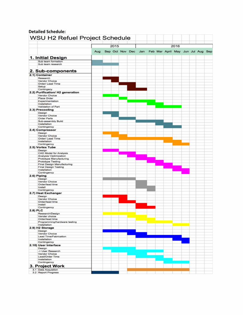
Detailed Schedule:

System Cost Sub-System Costs Table displaying subgroup power, space, and budget
Budget (Current Total~$300,000)
Component Power (kW) Space (ft^3) Low Estimate Single cost
High Estimate Single cost
Compressor 24 18 $80,000.00 $140,000.00
Container 0.5 0 $3,000.00 $5,000.00
Source 134 276 $100,000.00 $150,000.00
Storage 0 200 $50,000.00 $100,000.00
Piping/HX 0 20 $25,000.00 $30,000.00
PLC 0.01 5 $5,000.00 $15,000.00
Precooling 6 60 $10,000.00 $20,000.00
User Interface 0.1 4 $20,000.00 $25,000.00
Vortex 0 3 $3,000.00 $4,000.00
Total 164.61 586 $296,000.00 $489,000.00
Feedstock Cost for resources input to our system:
● Electricity: $336.07 per day. Based off 24 hour operation on 126.61 kW and 11.06 cents per kWh, average in the US (eia.gov, July, 2015, Commercial) (In Washington state this would be $247.95 per day due to lower power costs). (Source: http://www.eia.gov/electricity/monthly/epm_table_grapher.cfm?t=epmt_5_6_a)
● Water: $53.26 per day (based off 4000l/h at $2.10 per 1000 gallons. (based off tap water http://water.epa.gov/lawsregs/guidance/sdwa/upload/2009_08_28_sdwa_fs_30ann_dwsrf_web.pdf)
Permitting Cost ● Permitting and Fees: $650 (City of Pullman and WSU, 2014) –Richardson, Ian, et
al. 2014 Hydrogen Student Design Contest - Drop in Hydrogen Refueling Station. Washington State University, 2014.

Pathway to Commercialization
Introduction
The need for a viable business plan makes commercialization one of the most important aspects of developing hydrogen fueling technology. The following sections illustrate the necessary steps to commercialize and scale the system.
1. Formation of a business entity a. Creating a value proposition b. Identifying customer segments c. Managing customer relations d. Large scale manufacturing
2. Cost reductions a. Decrease in compressor costs b. Specialization of installation roles c. Increased bargaining power
3. Needed advances to go from an entry system to a commercially viable product
a. Vortex tube catalyst development b. Regulation changes c. Material advances d. Development of upgrades, warranties, and insurance policies e. Integration of greenfield locations f. Changes in public perception
4. Private investment potential Business Formation
The commercialization of our liquid hydrogen system relies on producing hydrogen in a convenient and cost effective manner. The following list shows some of the ways in which the commercialization process has already begun:
1. Formation of Protium Innovations LLC 2. Option to license the vortex tube patent from Washington State University 3. Vortex tube proof of concept 4. Development of minimal viable product
Figure: Protium Innovations Logo
Value Proposition
Talking to potential customers has allowed for the fine tuning of a two value propositions.
Value Propositions: 1. Providing value to our customers by supplying liquid hydrogen to an already existing
liquid hydrogen market in a convenient and cost effective manner. 2. Providing a method for producers of excess gaseous hydrogen to liquefy and sell their
excess hydrogen stream.
Customer Segments and Partners
Finding customers is the first step in increasing manufacturing at a larger scale. The following list shows potential customers and/or partners who have expressed interest in either liquid or gaseous hydrogen.
● Ag Energy Solutions ○ This company, located in Spokane, Wa, will act as both a partner and a customer.
They use excess plant biomass to produce gaseous hydrogen which we could then liquefy.
● Axiall ○ Axiall is a potential customer as they use hydrogen for the production of
hydrochloric acid. ● Canexus
○ Canexus is a potential customer as they use hydrogen for the production of hydrochloric acid.
● Cleantech Open ○ Accelerator aimed at the development of environmentally friendly startups.
● InEnTec ○ Turns municipal waste into various gases for energy purposes. Produces
hydrogen to be shipped and sold to the already existing hydrogen market. ● Reklaim
○ Produces large amounts of waste hydrocarbon and syngas. They would like to separate and resell the hydrocarbons and syngas for an additional revenue stream.
● Washington State University ○ Assisting in the technical development of the system.
Customer Relationship Management
Managing customer relations is an important part of keeping and growing our customer base. The primary customer relations we will be using are as follows:
● Excellent customer service ● Word of mouth ● Finding new customers through conferences, trade shows, networking, and current
equipment suppliers ● Referral programs
Large Scale Manufacturing
Our dispensing until will still need to provide the same value to the customers when produced at a large scale. The ability to provide liquid hydrogen in a cost effective and efficient manner will be the limiting factor to mass production. Changes to the system which hurt our ability to provide value to the customer will be unacceptable, even if they reduce systems cost.
The modularity of our system is very important for large scale manufacturing as various subcomponents can be improved and then mass produced without affecting the entire system. Deals can be made with specific suppliers for only one component. This allows us to find the best large scale manufacturing suppliers for each specific subcomponent as opposed to the entire system. In turn, this will cut down on large scale manufacturing costs while still optimizing the system to fit our value proposition goals. Cost Reduction
Stations which produce liquid hydrogen are currently much costlier than gaseous hydrogen stations. This is mainly a consequence of the costly components required to liquefy hydrogen. The Department of Energy (DOE) estimates that a liquid hydrogen station would cost $910,447 before installation1. Our costs will be closer to $400,000 as we avoid many of the capital intensive components by using a high efficiency vortex tube (see expected costs). Our system is already noticeably more affordable than current estimates, but over time we except further decreases in costs. The following shows some of the ways we will decrease costs as production grows. Compressor Costs
Based off of the DOE’s Hydrogen Refueling Station Analysis Model (HRSAM), compressors are the only major component in hydrogen liquefaction for which costs will decrease significantly with increased manufacturing production1. A decrease in the cost of compressors will decrease the cost of the entire station as compressors are the most expensive unit within the system. The DOE estimates that current compressor costs are roughly two times the cost today than their long term projections2. Specialized Installation Roles
We will utilize a specialized assembly format to more effectively install and test our product once larger production begins. Those building the system will have specialized roles which will cut back on installation time as well as ensure a more effective testing procedure to cut back on later maintenance costs. Our production model will follow lean manufacturing standards which have been developed in the last century by major car producers to achieve maximum efficiency. Increased Bargaining Power
Negotiating power on the part of the consumer will generally increase as buying increases. We expect that as our production increases we will have greater leverage which will allow for more affordable components.

Discussion of expected and/or needed advances to go from an entry system to a commercially viable product: To become a commercially viable product, we must first prove our ability to provide customers with a hydrogen fueling option based on our proprietary liquefaction technology. With this proof of concept, it is imperative the dispensing unit is successfully integrated into the current fueling infrastructure in compliance with the H2 fueling station guidance under development by the DOE / SAE J2601.
Figure: SAE Logo Figure: DOE Logo
The following list represents changes necessary to become a commercially viable product:
Vortex Tube Catalyst
The vortex tube is our primary competitive advantage, and the catalyst it utilizes will be effective in producing liquid hydrogen at high efficiencies. Finding a more effective catalyst will yield a larger competitive advantage and help our commercialization efforts. Regulations
Current regulations in both Washington State and elsewhere in the country somewhat limit the effectiveness of hydrogen fueling stations. Washington regulation WAC 296-24-31505, for example, sets the minimum distance of a fuel station from a concentrated group of people to 75 feet3. Many of these regulations will most likely change over time to be more in line with the regulations seen in the gas and oil industry. Materials
Advances in material science will help in the commercialization of our product. An increase in the effectiveness of the storage insulation, for example, will make the overall system more efficient. Upgrades, Warranty, and Insurance
Providing upgrades to liquefaction stations will be necessary as more advanced sub components are invented. Developing warranties and insurance systems will also be necessary to make buying or leasing a refueling station for economically attractive.

Integration of ‘Greenfield’ Locations with Current Infrastructure
Greenfield locations (i.e. land without any structures) are increasingly difficult to find in urban locations. Systems which use Greenfield locations will face difficulties integrating into urban settings unless an increase in Greenfield locations occurs. The DOE does not see Greenfield hydrogen stations being viable in urban areas as land is not readily available. Some changes in current infrastructure would benefit hydrogen dispensing units as they could be more easily introduced into urban areas. An example would be the conversion of an urban parking lot to a location for our fueling station1. Our dispensing unit is much smaller and more movable than other units. This gives us the advantage of being able to utilize some Greenfield locations that would generally be too small for other designs. Changes to current infrastructure to allow for more Greenfield locations, however, would still help our system become better integrated into urban settings.
Figure: Greenfield sites in urban areas are areas in which development could take place. They are very important for many hydrogen dispensing units. Public Perception
New technologies can often times be the subject of public scrutiny, and hydrogen is not an exception. Liquid hydrogen in urban settings has seen some resistance from the public over general safety concerns. Japan, for example, had problems installing a liquid hydrogen station as the public had fears about the safety of hydrogen1. Public perception of the safety of hydrogen must be addressed by means of education and outreach. Potential for private investment and manufacturing partners for components as well as systems integration: The entire system will be modular and any needed upgrades or exchanges can be made on a subsystem level. Manufacturers will need to be aware of component sizes for the various subsystems and different manufacturing partners may need to be in contact with one another to assure proper system integration. Private investors will be a necessary part of our system going forward. Investors and partners with connections to capital and transit routes will help the commercialization of our system progress. References
1. United States Department of Energy, Energy Efficiency & Renewable energy, Technical Report NREL/TP-5400-64107 SAND2015-2660 R. April 2015

2. Parks, G.; Boyd, R.; Cornish, J.; Remick, R. Hydrogen Station Compression, Storage, and Dispensing
3. Washington State Legislator, WAC 296-24-31505, liquid hydrogen systems, http://apps.leg.wa.gov/wac/default.aspx?cite=296-24-31505. Accessed 25 October 2015

H2-Refuel Sponsors Private Sponsors
1. Tim and Beverly Hesterberg 2. Paul Laufman 3. Don Shearer
Non-profit Sponsors
The M.J. Murdock Charitable Trust seeks to enrich the quality of life in the Pacific Northwest by providing grants and enrichment programs to nonprofit organizations that seek to strengthen the region’s educational, spiritual, and cultural base in creative and sustainable ways.
The Washington Research Foundation supports groundbreaking technology in the life sciences, information technology and physical sciences fields. By advancing brilliant research and early-stage entrepreneurs, the Washington Research Foundation helps to grow Washington’s technology economy.
Industry Sponsors
Dassault Systèmes SOLIDWORKS Corp. offers complete 3D software tools that let you create, simulate, publish, and manage your data. SOLIDWORKS products are easy to learn and use, and work together to help you design products better, faster, and more cost-effectively. The SOLIDWORKS focus on ease-of-use allows more engineers, designers and other technology professionals than ever before to take advantage of 3D in bringing their designs to life.


