19
Modular LNG Tanks John Powell and Brian Raine Gastech 2017 Tokyo, 4-7 April 2017
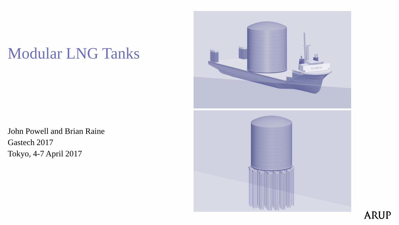
Modular LNG Tanks
John Powell and Brian Raine
Gastech 2017
Tokyo, 4-7 April 2017
2
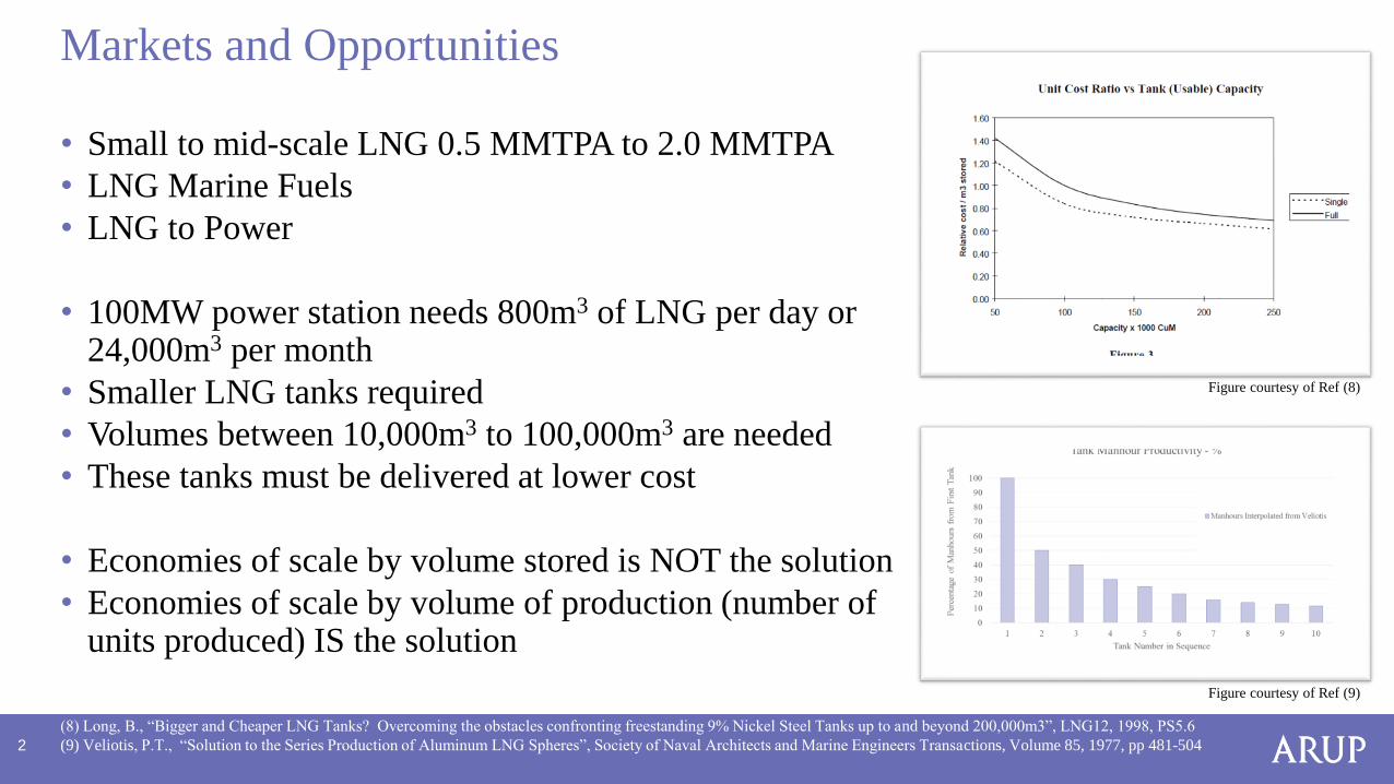
• Small to mid-scale LNG 0.5 MMTPA to 2.0 MMTPA
• LNG Marine Fuels
• LNG to Power
• 100MW power station needs 800m3 of LNG per day or 24,000m3 per month
• Smaller LNG tanks required
• Volumes between 10,000m3 to 100,000m3 are needed
• These tanks must be delivered at lower cost
• Economies of scale by volume stored is NOT the solution
• Economies of scale by volume of production (number of units produced) IS the solution
Markets and Opportunities
(8) Long, B., “Bigger and Cheaper LNG Tanks? Overcoming the obstacles confronting freestanding 9% Nickel Steel Tanks up to and beyond 200,000m3”, LNG12, 1998, PS5.6
(9) Veliotis, P.T., “Solution to the Series Production of Aluminum LNG Spheres”, Society of Naval Architects and Marine Engineers Transactions, Volume 85, 1977, pp 481-504
Figure courtesy of Ref (8)
Figure courtesy of Ref (9)
3
• Objectives for 10,000m3 to 100,000m3 LNG tanks
- Less than 24 months delivery schedule
- 20% lower CAPEX cost
• Key drivers
- Standardize tank design by volume based on site specific seismic isolation
- Offsite tank pre-fabrication in parallel with foundation construction
- Dedicated fabrication yard leading to improved productivities and higher quality
- Offsite pre-commissioning of tank
- Reduced manhours executed on site
• Target
- “Plug and play” capability
The Modular LNG Tank
4
• Papers and Presentations
- Raine, B. “Onshore Mid-Scale LNG Terminal Storage Modularization”, Trinidad Oil and Gas Conference, May 2014
- Raine, B., Powell, J., “Onshore Mid-Scale LNG Terminal Storage Modularization”, Gastech 2015, Singapore, October 27, 2015
• 2014-2015
- In-house development work carried out
• 2015-2016
- pre-FEED design, execution planning, scheduling and cost estimating carried out for 40k tanks in US and Caribbean, working with fabricators and transportation contractors
• 2016-2017
- Further development focusing on standard design by volume for any location
Development of Modular Tank Concept
5
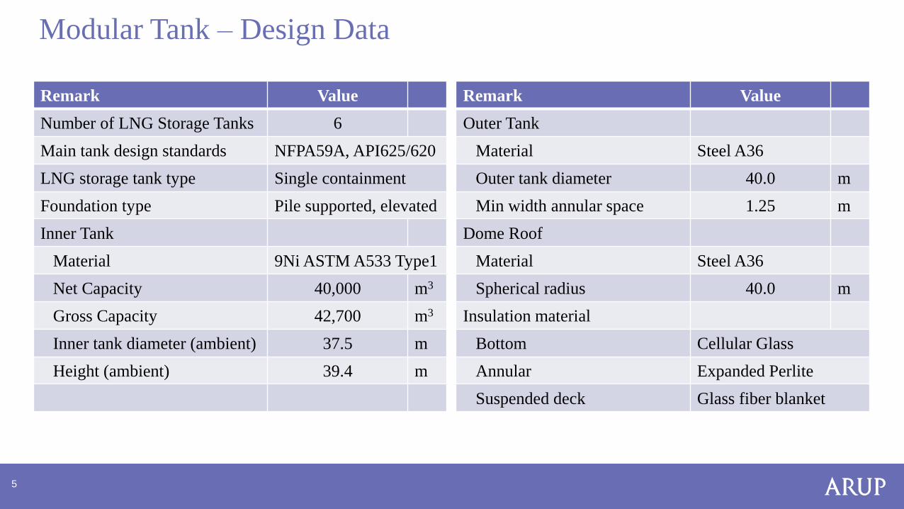
Remark Value
Number of LNG Storage Tanks 6
Main tank design standards NFPA59A, API625/620
LNG storage tank type Single containment
Foundation type Pile supported, elevated
Inner Tank
Material 9Ni ASTM A533 Type1
Net Capacity 40,000 m3
Gross Capacity 42,700 m3
Inner tank diameter (ambient) 37.5 m
Height (ambient) 39.4 m
Modular Tank – Design Data
Remark Value
Outer Tank
Material Steel A36
Outer tank diameter 40.0 m
Min width annular space 1.25 m
Dome Roof
Material Steel A36
Spherical radius 40.0 m
Insulation material
Bottom Cellular Glass
Annular Expanded Perlite
Suspended deck Glass fiber blanket
6
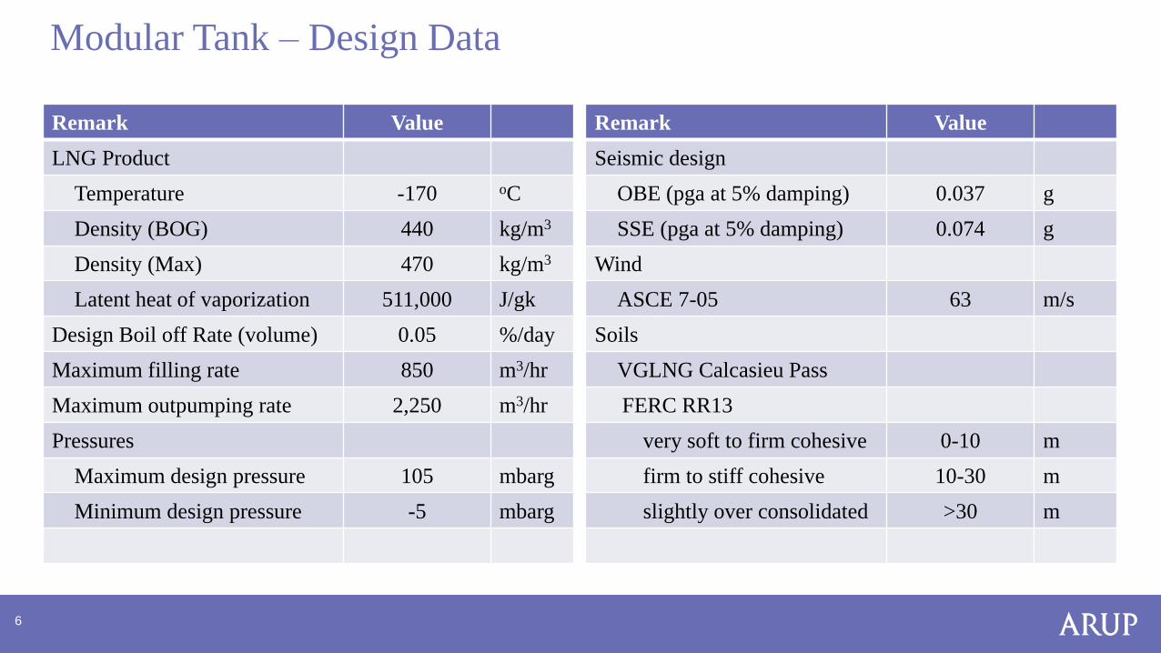
Remark Value
LNG Product
Temperature -170 oC
Density (BOG) 440 kg/m3
Density (Max) 470 kg/m3
Latent heat of vaporization 511,000 J/gk
Design Boil off Rate (volume) 0.05 %/day
Maximum filling rate 850 m3/hr
Maximum outpumping rate 2,250 m3/hr
Pressures
Maximum design pressure 105 mbarg
Minimum design pressure -5 mbarg
Modular Tank – Design Data
Remark Value
Seismic design
OBE (pga at 5% damping) 0.037 g
SSE (pga at 5% damping) 0.074 g
Wind
ASCE 7-05 63 m/s
Soils
VGLNG Calcasieu Pass
FERC RR13
very soft to firm cohesive 0-10 m
firm to stiff cohesive 10-30 m
slightly over consolidated >30 m
7
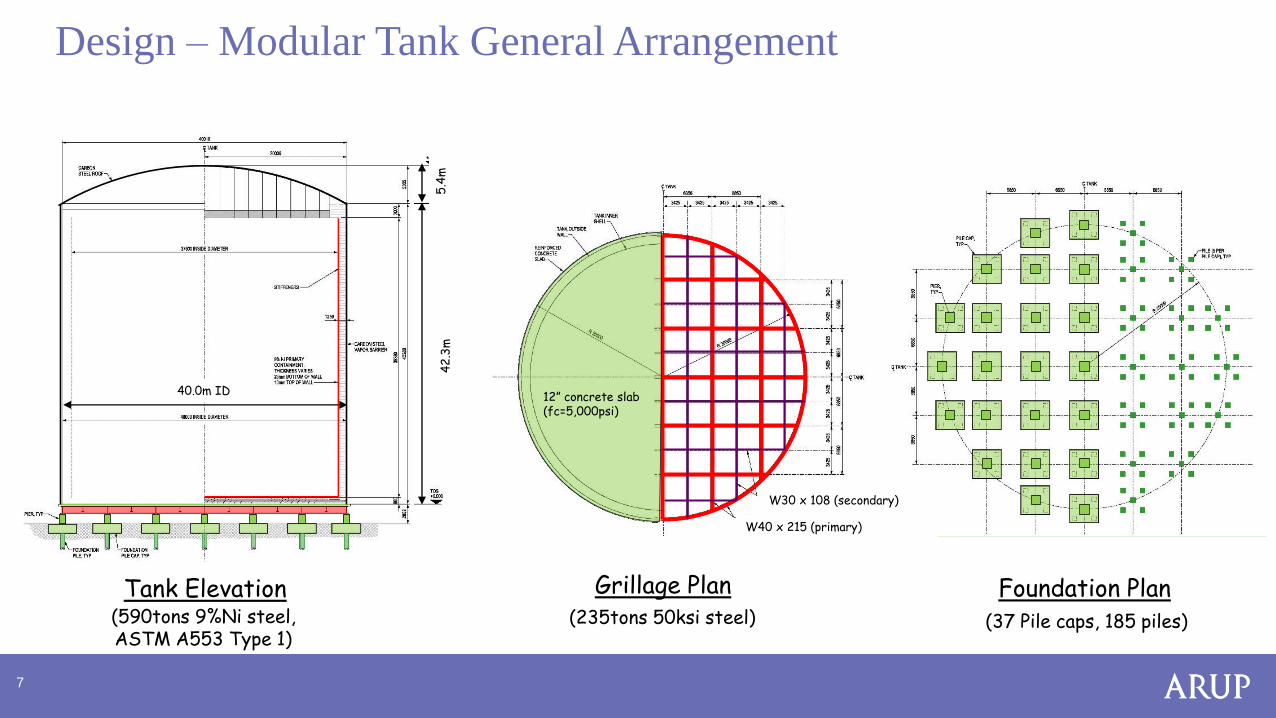
Design – Modular Tank General Arrangement
40.0m ID
42
.3m
5.4
m
Tank Elevation Grillage Plan Foundation Plan(37 Pile caps, 185 piles)(235tons 50ksi steel)
W30 x 108 (secondary)
W40 x 215 (primary)
(590tons 9%Ni steel, ASTM A553 Type 1)
12” concrete slab(fc=5,000psi)
8
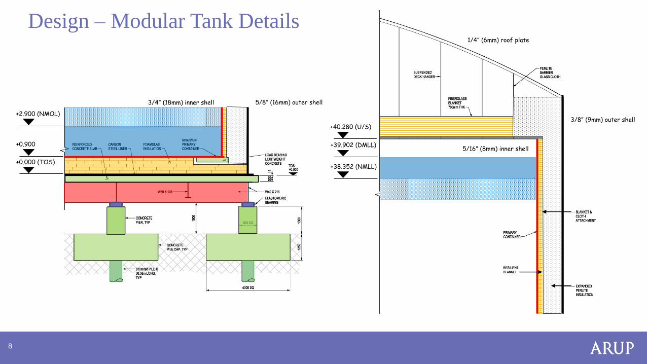
Design – Modular Tank Details
3/4” (18mm) inner shell
5/16” (8mm) inner shell
3/8” (9mm) outer shell
5/8” (16mm) outer shell
1/4” (6mm) roof plate
+0.000 (TOS)
+0.900
+2.900 (NMOL)
+40.280 (U/S)
+39.902 (DMLL)
+38.352 (NMLL)
9
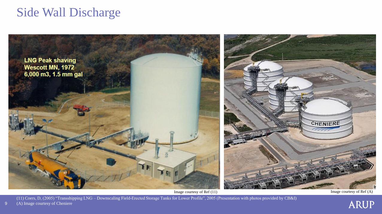
Side Wall Discharge
(11) Coers, D, (2005) “Transshipping LNG – Downscaling Field-Erected Storage Tanks for Lower Profile”, 2005 (Presentation with photos provided by CB&I)
(A) Image courtesy of Cheniere
Image courtesy of Ref (A)Image courtesy of Ref (11)
10
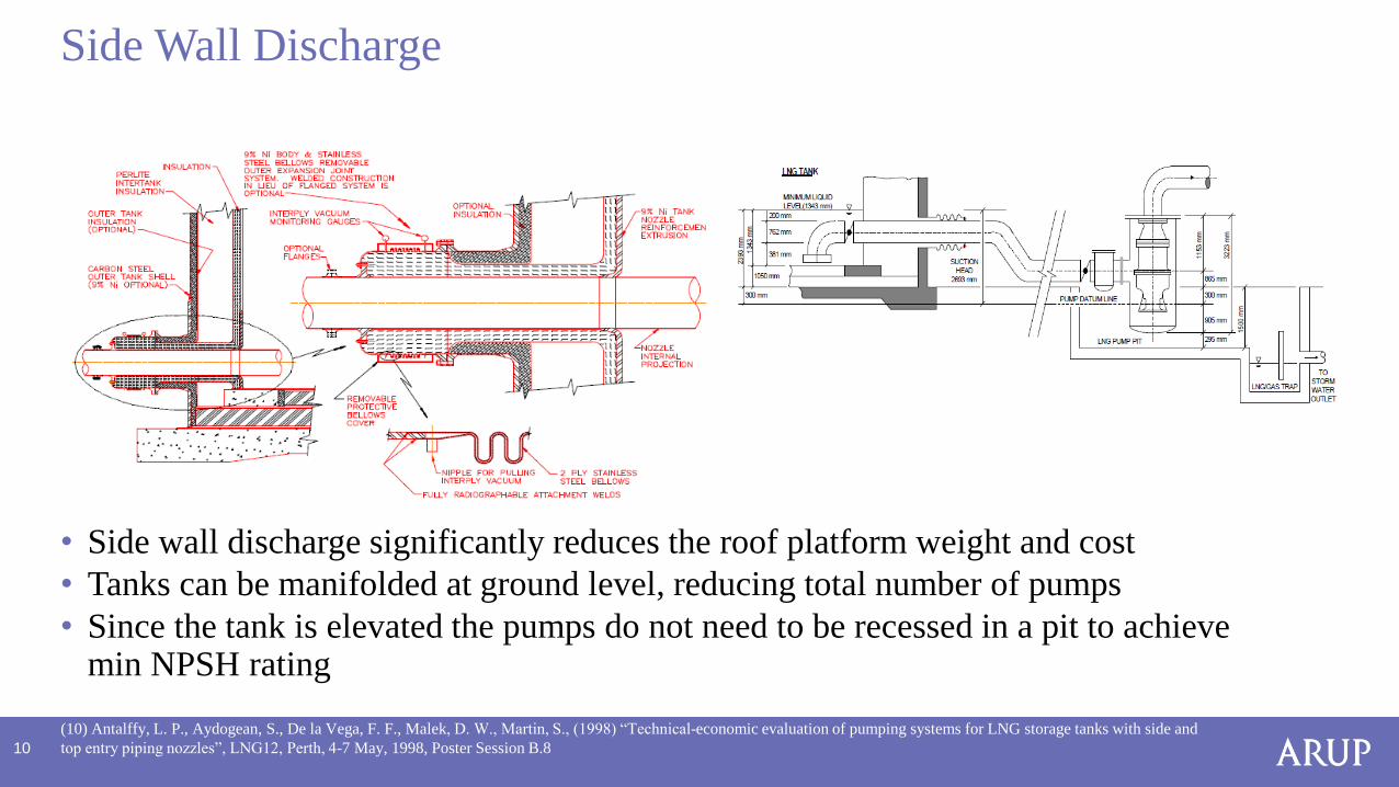
Side Wall Discharge
(10) Antalffy, L. P., Aydogean, S., De la Vega, F. F., Malek, D. W., Martin, S., (1998) “Technical-economic evaluation of pumping systems for LNG storage tanks with side and
top entry piping nozzles”, LNG12, Perth, 4-7 May, 1998, Poster Session B.8
• Side wall discharge significantly reduces the roof platform weight and cost
• Tanks can be manifolded at ground level, reducing total number of pumps
• Since the tank is elevated the pumps do not need to be recessed in a pit to achieve min NPSH rating
11
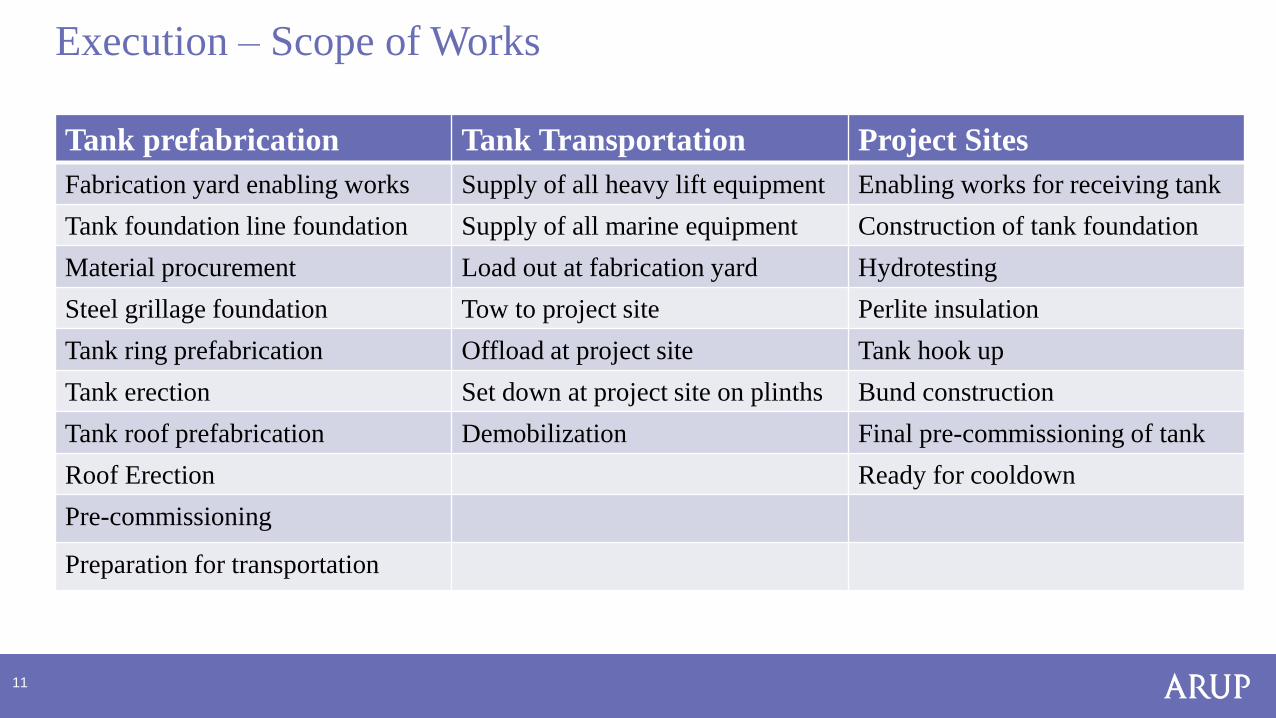
Tank prefabrication Tank Transportation Project Sites
Fabrication yard enabling works Supply of all heavy lift equipment Enabling works for receiving tank
Tank foundation line foundation Supply of all marine equipment Construction of tank foundation
Material procurement Load out at fabrication yard Hydrotesting
Steel grillage foundation Tow to project site Perlite insulation
Tank ring prefabrication Offload at project site Tank hook up
Tank erection Set down at project site on plinths Bund construction
Tank roof prefabrication Demobilization Final pre-commissioning of tank
Roof Erection Ready for cooldown
Pre-commissioning
Preparation for transportation
Execution – Scope of Works
12
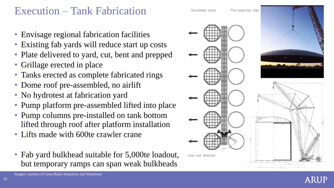
• Envisage regional fabrication facilities
• Existing fab yards will reduce start up costs
• Plate delivered to yard, cut, bent and prepped
• Grillage erected in place
• Tanks erected as complete fabricated rings
• Dome roof pre-assembled, no airlift
• No hydrotest at fabrication yard
• Pump platform pre-assembled lifted into place
• Pump columns pre-installed on tank bottom lifted through roof after platform installation
• Lifts made with 600te crawler crane
• Fab yard bulkhead suitable for 5,000te loadout, but temporary ramps can span weak bulkheads
Execution – Tank Fabrication
Images courtesy of Great Basin Industries and Mammoet
13
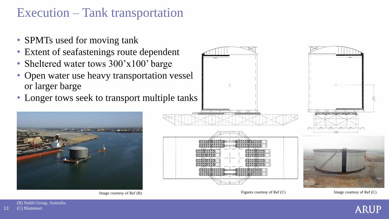
• SPMTs used for moving tank
• Extent of seafastenings route dependent
• Sheltered water tows 300’x100’ barge
• Open water use heavy transportation vessel or larger barge
• Longer tows seek to transport multiple tanks
Execution – Tank transportation
(B) Smith Group, Australia
(C) Mammoet
Image courtesy of Ref (B) Image courtesy of Ref (C)Figures courtesy of Ref (C)
14
• Tank erection is not waiting on construction of the project site tank foundation
- No onsite construction before permits obtained
- Many projects require significant onsite enabling works
• Tank fabrication and erection starts when material delivered to the fabrication yard
- Carbon steel material required first are on short lead times
- 9% Ni lead times of 12 to 18 months can be offset with material pre-ordering
- Established fabrication yard allows tank erection to start ahead of a stick built tank
• Labor intensive activities transferred from the project site to a dedicated fabrication yard
- Project sites often remote from large resource centers
- Specialist welders 9% Ni tank incurs a further premium for remote sites
- Established fabrication yard can provide a more reliable resource
• Improved productivities and quality at established fabrication yard
- Can invest in training and equipment to increase productivities and reduce costs
- Prefabrication of tank parts can be done in covered areas
•
Execution Plan – Key Benefits
15
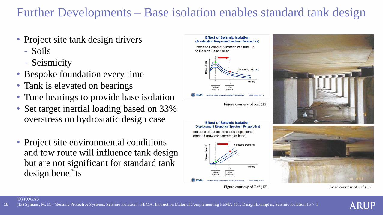
• Project site tank design drivers
- Soils
- Seismicity
• Bespoke foundation every time
• Tank is elevated on bearings
• Tune bearings to provide base isolation
• Set target inertial loading based on 33% overstress on hydrostatic design case
• Project site environmental conditions and tow route will influence tank design but are not significant for standard tank design benefits
Further Developments – Base isolation enables standard tank design
(D) KOGAS
(13) Symans, M. D., “Seismic Protective Systems: Seismic Isolation”, FEMA, Instruction Material Complementing FEMA 451, Design Examples, Seismic Isolation 15-7-1
Figure courtesy of Ref (13) Image courtesy of Ref (D)
Figure courtesy of Ref (13)
16
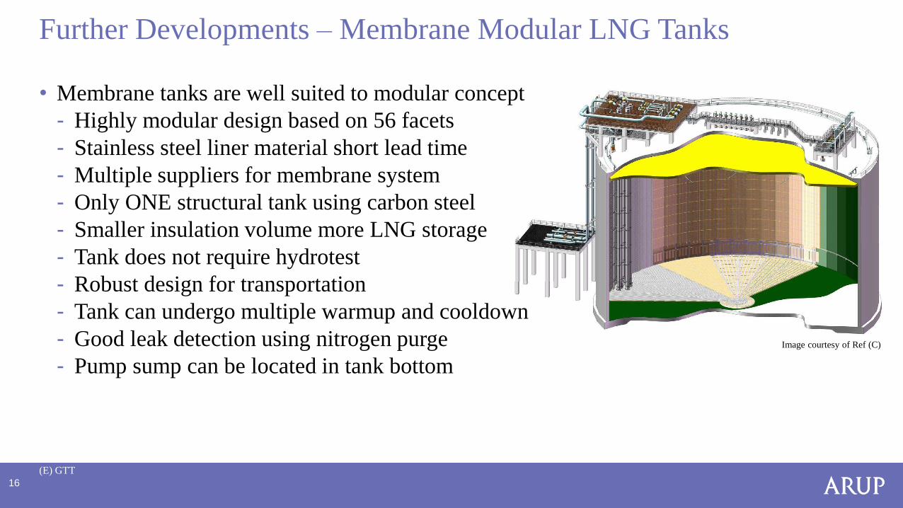
• Membrane tanks are well suited to modular concept
- Highly modular design based on 56 facets
- Stainless steel liner material short lead time
- Multiple suppliers for membrane system
- Only ONE structural tank using carbon steel
- Smaller insulation volume more LNG storage
- Tank does not require hydrotest
- Robust design for transportation
- Tank can undergo multiple warmup and cooldown
- Good leak detection using nitrogen purge
- Pump sump can be located in tank bottom
Further Developments – Membrane Modular LNG Tanks
(E) GTT
Image courtesy of Ref (C)
17
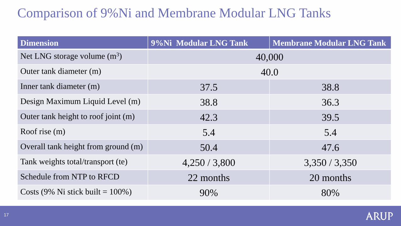
• dfd
Comparison of 9%Ni and Membrane Modular LNG Tanks
Dimension 9%Ni Modular LNG Tank Membrane Modular LNG Tank
Net LNG storage volume (m3) 40,000
Outer tank diameter (m) 40.0
Inner tank diameter (m) 37.5 38.8
Design Maximum Liquid Level (m) 38.8 36.3
Outer tank height to roof joint (m) 42.3 39.5
Roof rise (m) 5.4 5.4
Overall tank height from ground (m) 50.4 47.6
Tank weights total/transport (te) 4,250 / 3,800 3,350 / 3,350
Schedule from NTP to RFCD 22 months 20 months
Costs (9% Ni stick built = 100%) 90% 80%
18
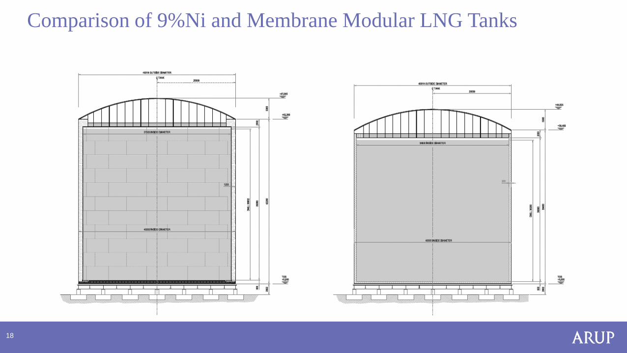
Comparison of 9%Ni and Membrane Modular LNG Tanks
19
• Technical feasibility of the modular LNG tank has been studied and proven
• Membrane modular LNG tanks offer clear advantages over 9% Ni modular LNG tanks
• “Plug and Play” capability is achievable
- based on a standard design that can be installed for any site, anywhere in the world
- resulting in cheaper and quicker prefabricated small to medium sized tanks
• Not every site wants or can permit a Single Containment Modular LNG Tank design
• Full Containment Modular LNG Tank designs are too heavy to transport cost effectively
• Precast concrete full containment with membrane liner offers significant opportunities to reduce cost and schedule
• The LNG to Power market needs cheaper tanks
• Modular LNG tank designs addresses this need
Conclusions


