Modular multistage pumps SIHI multi Type MSC PUMP TECHNOLOGY SIHI multi MSC 133.23304.54.01 E 05/2015 Description The SIHI multi MSC range of horizontal, ring-section multi- stage pumps have been designed for long-term reliability when pumping high pressure liquids. The design features within this range of high pressure pumps, provide our cus- tomers with unique solutions to long-term concerns about power consumption, efficiency, and reliability. A special feature is the wide range of speed, which is excel- lent suitable for frequency inverter running. Meeting the technical requirements of ISO 5199 / EN25199, they have a modular concept in order to reduce the number of parts, and consequently our customers’ inventory. Premium levels of efficiency are available by selecting an appropriate set of impellers and diffusers that give an ideal fit to the process requirement. Unique to the multi-stage arena portfolio is the, SIHI, patented self-adjusting drum style of axial thrust balancing. The MSC employ a device that reduces the bypass flow to an absolute minimum, while not being susceptible to long(er) term wear-sensitive clear- ances. Applications Pumps of the SIHI multi range meet the specific requirements of our customers in selected applications, such as Renewable energy Fossil power stations Biomass Geothermal Paper and Pulp Optional special designs Customised solutions, which are not covered by the stand- ard design, like de-staging decive, interstage bleed-off or different sealing options are possible on request. Materials Suction-, Stage- and Discharge casing: Chrome steel Impeller/Diffuser: Grey cast iron or stainless steel Shaft: Chrome steel Technical Data Flow rate: max. 250 m³/h Head: max. 1000 m Medium temperature: -10°C to +180°C Speed: 400 to 3600 rpm Final pressure: max. 100 bar Shaft sealing packed gland or mechanical seal Direction of rotation counter-clockwise, when viewed from discharge side Construction Different hydraulic impeller and diffuser sizes can be in- stalled in a standard casing, thus enabling the pump to be designed exactly for the duty point required. The first stage of each pump size is equipped with an optimised NPSH suction impeller. Axial thrust is hydraulically balanced by a patented balance drum system with a self-adjusting throttling device. Residual thrust is absorbed by a generously sized angular-contact ball bearing. The balancing line is returned to the suction casing. The pump rotor is supported on the drive side by grease lubricated anti-friction bearings. Support on the suction side is effected by means of a low-velocity product lubricated, and self-aligning sleeve bearing. The pump is driven from the discharge side, in a counter- clockwise direction, when viewed from the discharge side. Simple installation adaptation is possible with the modular design which allows discharge casing flange to be supplied radially upwards, horizontal-left or horizontal-right. The pump is usually constructed with an axial or radial inlet suc- tion. As standard the pump is mounted with integrated thermal compensation. The shaft sealing consist of a single-acting mechanical seal, or optionally as packed gland configuration. These two exe- cutions are supported with an internal circulation flow. For even higher liquid temperatures, the pumps can be supplied with an optional external jacket-cooling. The static casing sealing, consist of EPDM O-rings, as standard, with the option of FKM material. Condition-based monitoring, via the SIHI detect type of vibra- tion device, is optional in which to give advanced failure warning. Other standard equipment is available to monitor: Suction and discharge pressure; Liquid temperature; and bearing temperature. Low pressure-drop, filters can be sup- plied for use of the suction side of the pump, as can mini- mum flow-bypass valves.
Transcript
Modular multistage pumps
SIHImulti
Type MSC
PUMP TECHNOLOGY SIHImulti MSC
133.23304.54.01 E 05/2015
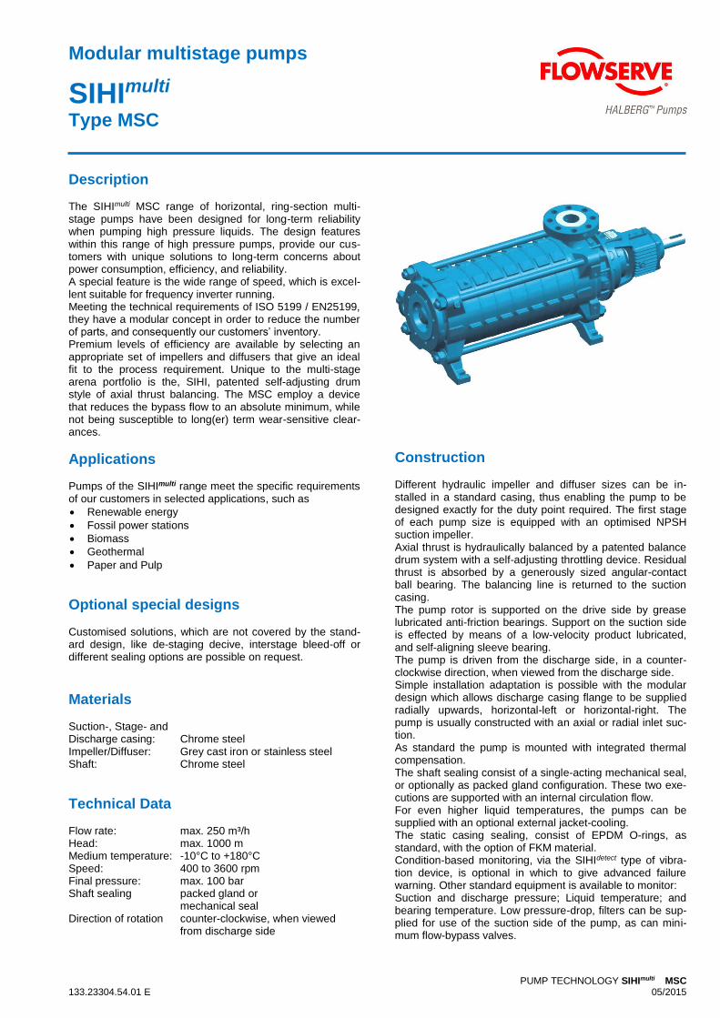
Description The SIHImulti MSC range of horizontal, ring-section multi-stage pumps have been designed for long-term reliability when pumping high pressure liquids. The design features within this range of high pressure pumps, provide our cus-tomers with unique solutions to long-term concerns about power consumption, efficiency, and reliability. A special feature is the wide range of speed, which is excel-lent suitable for frequency inverter running. Meeting the technical requirements of ISO 5199 / EN25199, they have a modular concept in order to reduce the number of parts, and consequently our customers’ inventory. Premium levels of efficiency are available by selecting an appropriate set of impellers and diffusers that give an ideal fit to the process requirement. Unique to the multi-stage arena portfolio is the, SIHI, patented self-adjusting drum style of axial thrust balancing. The MSC employ a device that reduces the bypass flow to an absolute minimum, while not being susceptible to long(er) term wear-sensitive clear-ances.
Applications Pumps of the SIHImulti range meet the specific requirements of our customers in selected applications, such as
Renewable energy
Fossil power stations
Biomass
Geothermal
Paper and Pulp
Optional special designs Customised solutions, which are not covered by the stand-ard design, like de-staging decive, interstage bleed-off or different sealing options are possible on request.
Materials Suction-, Stage- and Discharge casing: Chrome steel Impeller/Diffuser: Grey cast iron or stainless steel Shaft: Chrome steel
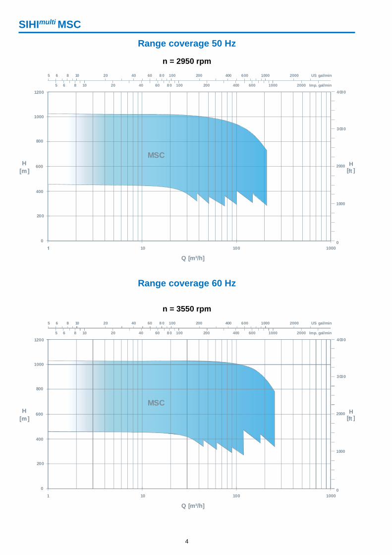
Technical Data Flow rate: max. 250 m³/h Head: max. 1000 m Medium temperature: -10°C to +180°C Speed: 400 to 3600 rpm Final pressure: max. 100 bar Shaft sealing packed gland or mechanical seal Direction of rotation counter-clockwise, when viewed from discharge side
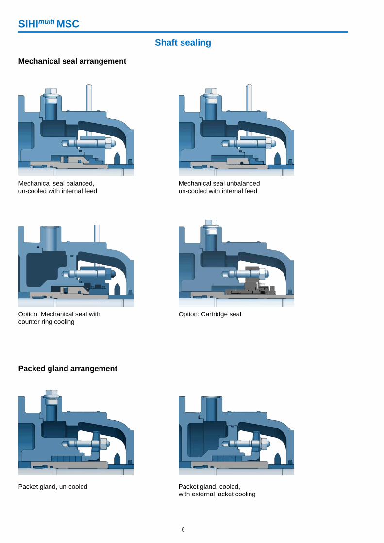
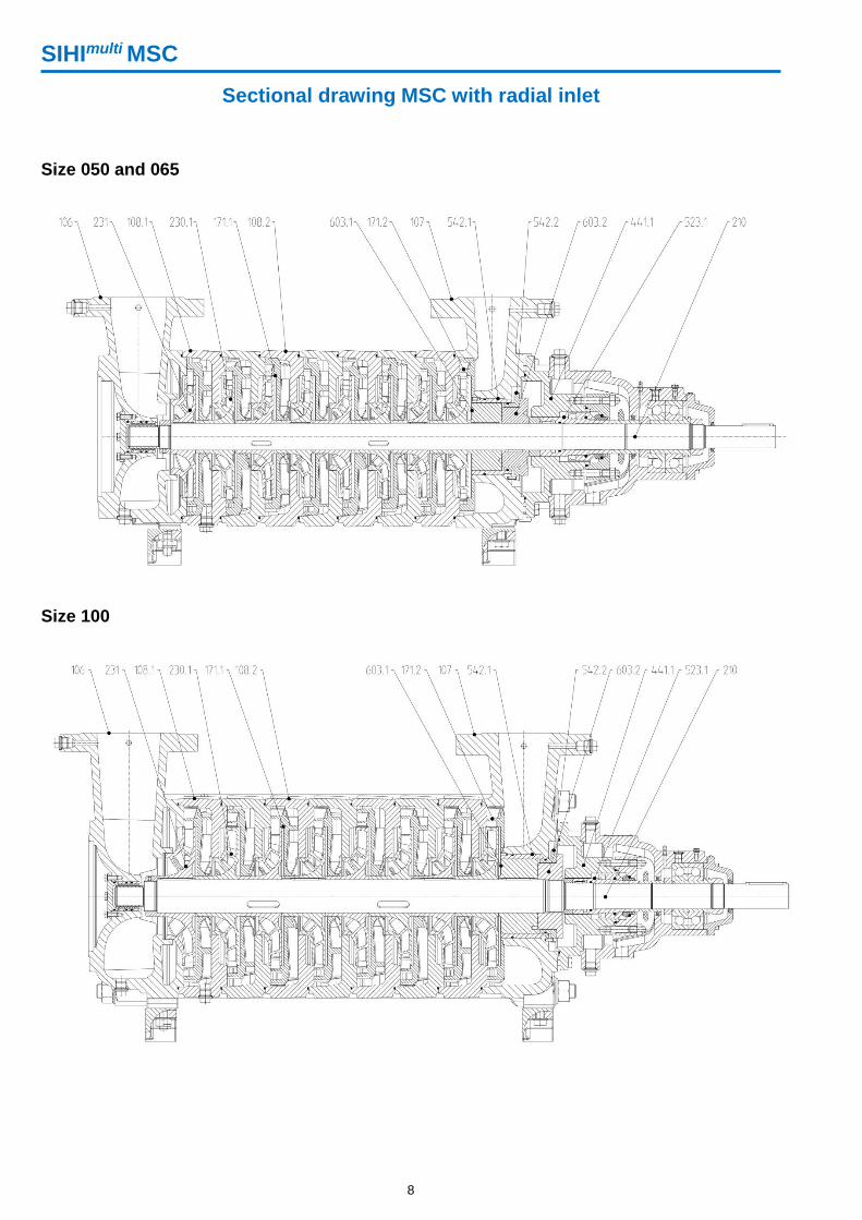
Construction Different hydraulic impeller and diffuser sizes can be in-stalled in a standard casing, thus enabling the pump to be designed exactly for the duty point required. The first stage of each pump size is equipped with an optimised NPSH suction impeller. Axial thrust is hydraulically balanced by a patented balance drum system with a self-adjusting throttling device. Residual thrust is absorbed by a generously sized angular-contact ball bearing. The balancing line is returned to the suction casing. The pump rotor is supported on the drive side by grease lubricated anti-friction bearings. Support on the suction side is effected by means of a low-velocity product lubricated, and self-aligning sleeve bearing. The pump is driven from the discharge side, in a counter-clockwise direction, when viewed from the discharge side. Simple installation adaptation is possible with the modular design which allows discharge casing flange to be supplied radially upwards, horizontal-left or horizontal-right. The pump is usually constructed with an axial or radial inlet suc-tion. As standard the pump is mounted with integrated thermal compensation. The shaft sealing consist of a single-acting mechanical seal, or optionally as packed gland configuration. These two exe-cutions are supported with an internal circulation flow. For even higher liquid temperatures, the pumps can be supplied with an optional external jacket-cooling. The static casing sealing, consist of EPDM O-rings, as standard, with the option of FKM material. Condition-based monitoring, via the SIHIdetect type of vibra-tion device, is optional in which to give advanced failure warning. Other standard equipment is available to monitor: Suction and discharge pressure; Liquid temperature; and bearing temperature. Low pressure-drop, filters can be sup-plied for use of the suction side of the pump, as can mini-mum flow-bypass valves.
SIHImulti MSC
2
Reliability with low NPSH Enhanced first stage suction impeller
size and geometry. Compact system design due to low suc-
tion head.
Self-adjusting sleeve bearing Only one shaft seal. Self-adjusting for higher reliability. Reliable flushing at high temperatures and
low speed. Prepared for frequency inverter running
Optimum process fit Modular sets of impellers & diffusers
for perfect duty match. Optimised efficiency over the perfor-
mance range
Non-distorted assembly With integrated thermal compensation (ITC)
as standard. No installation or adjustment necessary.
Adaptable suction connection Axial or radial suction case positions
MSH (please see specific brochure)
MSC
MSM (please see specific brochure)
MSL (please see specific brochure)
Optimized streaming diffuser geometry Optimized flow pattern Short inlete piping possible
SIHImulti MSC
3
Balance drum system secures long-term premium efficiency Patented balance drum system for axial thrust bal-
ancing. Applicable also for Start/Stop cycles. Reduced internal bypass flow, and associated
losses. Self-adjusting. Maintenance free, no wear parts.
Reliable sealing solutions Single or double acting mechanical seal. Cooled or un-cooled. Packed gland.
Benefits
Reduced life-cycle cost - higher efficiency due to SIHI patented balance
drum system
- only one shaft seal
- lower power consumption
- high reliability
Ready for SIHIdetect Connection for condition-based
monitoring via SIHIdetect available. Applicable for measurements of
- Suction pressure - Final pressure - Liquid temperature - Bearing temperature - Casing vibration
Adaptable discharge connection Discharge casing flange to be supplied
radially upwards, horizontal-left or horizon-tal-right.
Nominal size, nominal pressure and flange rating with end suction
Size Flanges
Suction side Discharge side
drilled acc. to
DN1 ØK1 n x ØL1 drilled acc. to
DN2 ØD2 C ØK2 n x ØL2
050
1 PN 16 100 180 8 x M16
PN 100 50 195 36 145 4 x 26 2 PN 25 100 190 8 x M20
A Class 300 100 (4“) 200 8 x ¾“ UNC Class 600 50 (2“) 195 37 127 8 x 19
065
1 PN 16 125 210 8 x M16
PN 100 65 220 37 170 8 x 26 2 PN 25 125 220 8 x M24
A Class 300 125 (5“) 235 8 x ¾“ UNC Class 600 65 (2½“) 220 38 149,2 8 x 22
100
1 PN 16 150 240 8 x M20
PN 100 100 265 43 210 8 x 30 2 PN 25 150 250 8 x M24
A Class 300 150 (6“) 269,9 12 x ¾“ UNC Class 600 100 (4“) 265 45 215,9 8 x 26
Dimensions in mm
Note: The axial suction casings are supplied with the required threaded blind holes.
SIHImulti MSC
13
Nominal size, nominal pressure and flange rating with radial inlet
Size Flanges Suction side Discharge side
drilled acc. to
DN1 Ø D1 C1 Ø K1 n x Ø L1 drilled acc. to
DN2 Ø D2 C2 Ø K2 n x Ø L2
050
1 PN 16 80 200 35 160 8 x 18 PN 100 50 195 36 145 4 x 26
2 PN 25 80 200 35 160 8 x 18
A Class 300 80 (3") 210 35 168,3 8 x 23 Class 600 50 (2") 195 37 127 8 x 19
065
1 PN 16 100 220 34 180 8 x 18 PN 100 65 220 37 170 8 x 26
2 PN 25 100 235 34 190 8 x 22
A Class 300 100 (4") 254 34 200 8 x 23 Class 600 65 (2 1/2") 220 38 149,2 8 x 22
100
1 PN 16 125 250 36 210 8 x 18 PN 100 100 265 43 210 8 x 30
2 PN 25 125 270 36 220 8 x 26
A Class 300 125 (5") 279 36 234,9 8 x 23 Class 600 100 (4") 265 45 215,9 8 x 26
Dimensions in mm
SIHImulti MSC
14
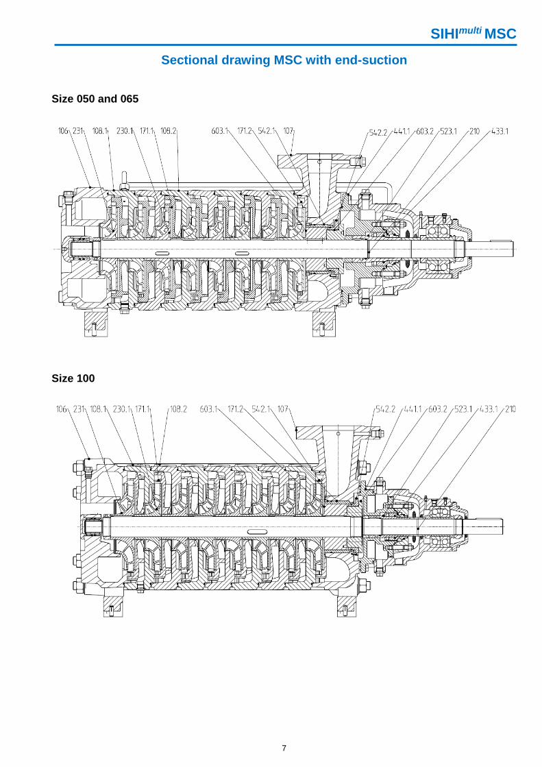
Connections with end-suctions
Connections with radial inlet
Pos. Connection Size
Pos. Connection Size
050 065, 100 050 065, 100
I Measurement of discharge pres-
sure or liquid temperature 3 x G 1/2
XIa external jacket-cooling
(inlet) G 3/8 G 1/2
XIb external jacket-cooling
(outlet) G 3/8 G 1/2
II Measurement of suction pres-
sure or liquid temperature 2 x G 1/2 XII Circulation pipe 2 x G 1/4
III Shaft seal vent/flush G 1/4 XX Grease lubrication anti-friction bearing
DIN 71412- A M6
VII Drain G 3/8 G 1/2 XXIV Measurement of
bearing temperature G 1/4
IX Seal drain G 3/8 G 3/4 XXX SIHIdetect
or measurement thrust impulse 3x M8
SIHImulti MSC
15
Additional innovative solutions from SIHI
SIHIdetect Condition based monitoring Detect wear before damage occurs
+ Cavitation and process turbulence + Simple to connect + LED display + Available Ex + All rotating machinery + DCS integration and continual monitoring Noise and Vibration analysis allows this compact device to diagnose the (often hid-den) symptoms of longer term damage even before vibration occurs.
SIHImulti MSH Boiler feed pumps Multistage centrifugal pumps Flowrate: up to 250 m³/h Head: up to 1,600 m Materials: Chrome steel
MSL Condensate pumps Multistage centrifugal pumps Flowrate: up to 450 m³/h Head: up to 400 m Materials: Cast iron, stainless steel
SIHIprime CEH Low NPSH pumps Side channel pumps Flowrate: up to 35 m³/h Head: up to 354 m Materials: Cast iron, stainless steel
SIHISuperNova ZLN Cooling water pumps Single stage Volute casing pumps Flowrate: up to 1,800 m³/h Head: up to 140 m Materials: Cast iron, stainless steel