31
Modularisation of Bioenergy Systems Tony Bridgwater [email protected] Aston University Bioenergy Research Group, European Bioenergy Research Institute Birmingham B4 7ET, UK

Modularisation of Bioenergy Systems
Tony [email protected]
Aston University Bioenergy Research Group, European Bioenergy Research Institute
Birmingham B4 7ET, UK
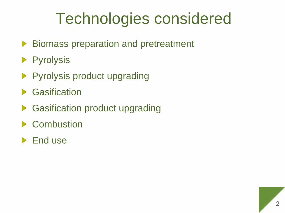
Technologies considered Biomass preparation and pretreatment
Pyrolysis
Pyrolysis product upgrading
Gasification
Gasification product upgrading
Combustion
End use
2

Process steps for bioenergy & biofuelsBiomass reception storage and handlingBiomass preparation e.g. comminution, screening, dryingPretreatment by torrefactionFast pyrolysisBio-oil upgrading including gasification
Product refiningOffsites including power and heat provision
Gasification of biomass or bio-oil Oxygen for gasification Gas cleaning for qualityGas conditioning for compositionPotential for CCSSynthesis of biofuels (H/C or -OH)Conversion of alcohols to H/C
3
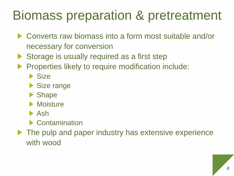
Biomass preparation & pretreatmentConverts raw biomass into a form most suitable and/or necessary for conversionStorage is usually required as a first step Properties likely to require modification include:
SizeSize rangeShapeMoistureAshContamination
The pulp and paper industry has extensive experience with wood
4

Preparation & pretreatment
Re-shredScreenRe-chip
Magnet
ShredChip
Store & reclaim in stacksStore & reclaim in piles
Dry (optional)
Gasification
Grind
Screen
Dry to <10% water
Torrefaction
Reception, Storage
and Handling
Preparation
Pretreat-ment
Reception chips
Reception chunks
Reception bundles
Reception bales
Solid biomass
Bio-oilBio-oil upgrading
Fast pyrolysis
Conversion
Established operations in the pulp
and paper industry
System designA biomass preparation and pretreatment system design depends on the feed material and the conversion processExtensive experience is available for wood, less so for other types of biomass and waste
6
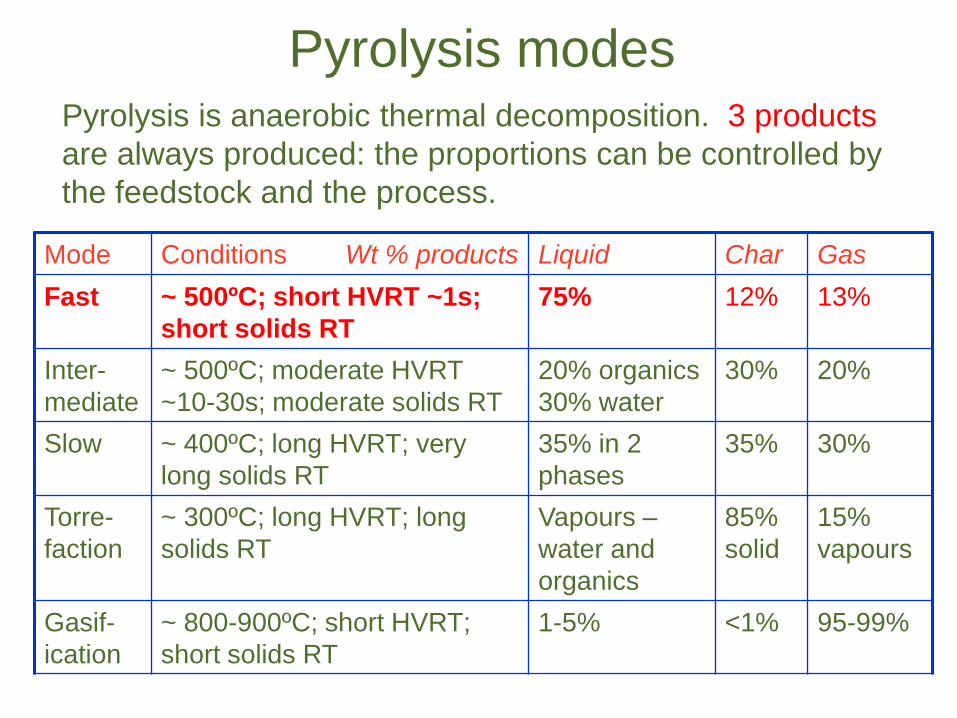
Pyrolysis modes
Mode Conditions Wt % products Liquid Char GasFast ~ 500ºC; short HVRT ~1s;
short solids RT75% 12% 13%
Inter-mediate
~ 500ºC; moderate HVRT ~10-30s; moderate solids RT
20% organics30% water
30% 20%
Slow ~ 400ºC; long HVRT; very long solids RT
35% in 2 phases
35% 30%
Torre-faction
~ 300ºC; long HVRT; long solids RT
Vapours –water and organics
85%solid
15%vapours
Gasif-ication
~ 800-900ºC; short HVRT; short solids RT
1-5% <1% 95-99%
Pyrolysis is anaerobic thermal decomposition. 3 products are always produced: the proportions can be controlled by the feedstock and the process.
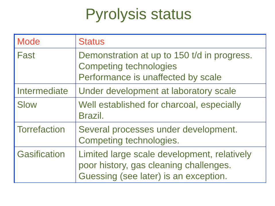
Pyrolysis status
Mode StatusFast Demonstration at up to 150 t/d in progress.
Competing technologiesPerformance is unaffected by scale
Intermediate Under development at laboratory scaleSlow Well established for charcoal, especially
Brazil.Torrefaction Several processes under development.
Competing technologies.Gasification Limited large scale development, relatively
poor history, gas cleaning challenges. Guessing (see later) is an exception.

Fast pyrolysis requirementsThe aim is to maximise the organics as liquids. These can be directly use or converted to fuels and chemicals.
Fast pyrolysis requires:High heating rates: Small particle sizes < 3-4 mm are needed as biomass has low thermal conductivityDry biomass (<10wt.% water): Water in feed goes into bio-oil product plus reaction waterCarefully controlled temperature: ~500°C is optimum for maximising liquid yield, (but not necessarily quality)Rapid and effective char removal: Char and alkali metals are catalytic and reduce liquid yieldShort hot vapour residence time: Thermal cracking reduces liquid yieldRapid vapour cooling to minimise secondary reactions
These specifications dictate the design 9
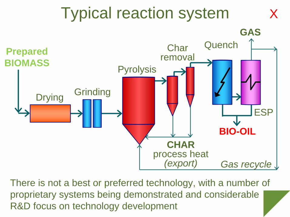
Typical reaction system
Prepared BIOMASS
Gas recycle
CHARprocess heat
(export)
QuenchGAS
BIO-OIL
ESP
GrindingDrying
Pyrolysis
Char removal
There is not a best or preferred technology, with a number of proprietary systems being demonstrated and considerable R&D focus on technology development
X

Variables in reaction system
Fluid bedTransported bed
CFBAblative
etcQuench
Heat exchangeretc
ESPCoalescerDemister
Centifugal s’tor+combinations
Or none
Cyclone(s)HV Filter
+combinationsRotary kilnMoving bed
SiloSteam
etc
Hammer millKnife millBall mill
etc+combinations
WoodGrassesAg-waste
MSWetc.
Prepared BIOMASS
Gas recycle
CHARprocess heat
(export)
QuenchGAS
BIO-OIL
ESP
GrindingDrying
Pyrolysis
Char removal
X
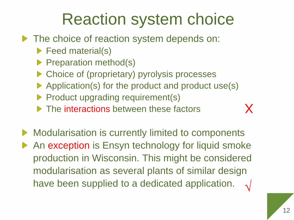
Reaction system choiceThe choice of reaction system depends on:
Feed material(s)Preparation method(s)Choice of (proprietary) pyrolysis processesApplication(s) for the product and product use(s)Product upgrading requirement(s)The interactions between these factors
Modularisation is currently limited to componentsAn exception is Ensyn technology for liquid smoke production in Wisconsin. This might be considered modularisation as several plants of similar design have been supplied to a dedicated application. √
X
12
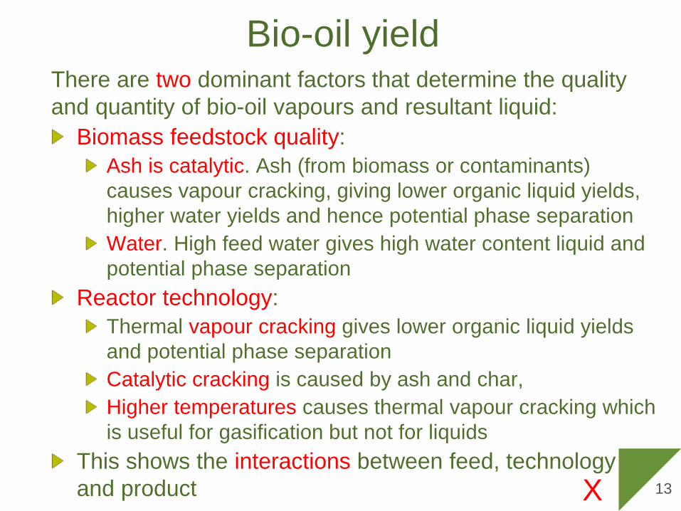
Bio-oil yieldThere are two dominant factors that determine the quality and quantity of bio-oil vapours and resultant liquid:
Biomass feedstock quality:Ash is catalytic. Ash (from biomass or contaminants) causes vapour cracking, giving lower organic liquid yields, higher water yields and hence potential phase separationWater. High feed water gives high water content liquid and potential phase separation
Reactor technology:Thermal vapour cracking gives lower organic liquid yields and potential phase separationCatalytic cracking is caused by ash and char, Higher temperatures causes thermal vapour cracking which is useful for gasification but not for liquids
This shows the interactions between feed, technology and product X 13
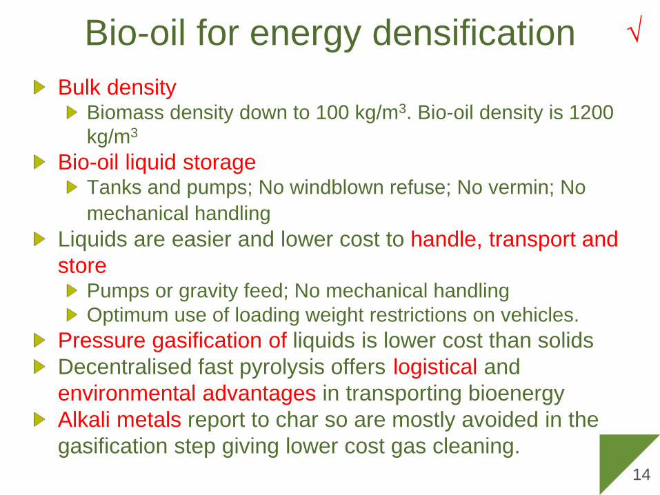
Bio-oil for energy densification
14
Bulk densityBiomass density down to 100 kg/m3. Bio-oil density is 1200 kg/m3
Bio-oil liquid storageTanks and pumps; No windblown refuse; No vermin; No mechanical handling
Liquids are easier and lower cost to handle, transport and store
Pumps or gravity feed; No mechanical handlingOptimum use of loading weight restrictions on vehicles.
Pressure gasification of liquids is lower cost than solidsDecentralised fast pyrolysis offers logistical andenvironmental advantages in transporting bioenergyAlkali metals report to char so are mostly avoided in the gasification step giving lower cost gas cleaning.
√

Decentralised fast pyrolysis & local use
15
Decentralised fast pyrolysis systems could use modularisation when concepts and technology are better established
Central processor
e.g. biofuel
Local use
√

Decentralised fast pyrolysis concept
Gasn.
Synthesis
Feed
Feed
Feed
Feed
Feed
Multiple fast pyrolysis units
Higher cost for pyrolysis units, lower costs for gasification16
√
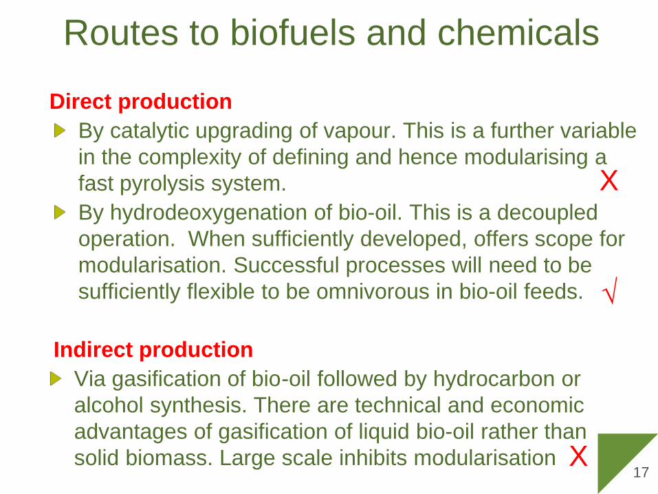
Routes to biofuels and chemicals
Direct productionBy catalytic upgrading of vapour. This is a further variable in the complexity of defining and hence modularising a fast pyrolysis system. By hydrodeoxygenation of bio-oil. This is a decoupled operation. When sufficiently developed, offers scope for modularisation. Successful processes will need to be sufficiently flexible to be omnivorous in bio-oil feeds.
Indirect production Via gasification of bio-oil followed by hydrocarbon or alcohol synthesis. There are technical and economic advantages of gasification of liquid bio-oil rather than solid biomass. Large scale inhibits modularisation
√
X
X17
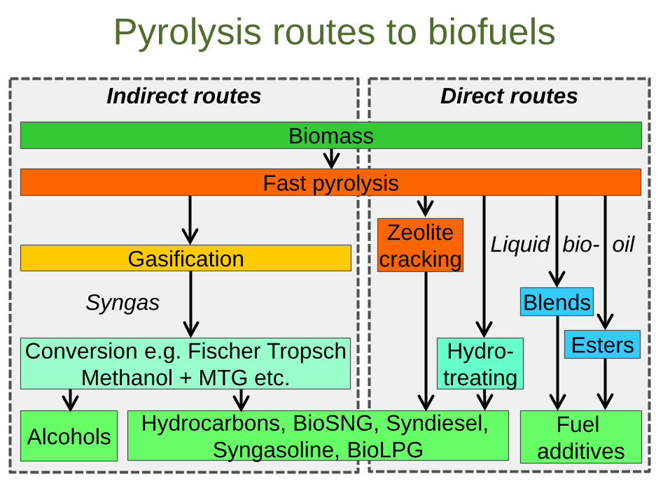
Direct routesIndirect routes
Pyrolysis routes to biofuels
Hydrocarbons, BioSNG, Syndiesel, Syngasoline, BioLPG
Syngas
Zeolitecracking
Liquid bio- oil
Alcohols
Gasification
Hydro-treating
Conversion e.g. Fischer TropschMethanol + MTG etc.
Fast pyrolysis
Fuel additives
Esters
Blends
Biomass

Gasification of bio-oil
Remote and/or decentralised fast pyrolysis considers transporting liquefied biomass as bio-oil to a central gasification plant for synthesis of hydrocarbons or alcoholsLiquids are easier and lower cost to transport than solidsLiquids can be more easily and economically gasified than solid biomass (e.g. no lock hoppers) i.e. lower costAbsence of ash reduces slagging and corrosion/erosion in gasifier i.e. lower costSubsequent biofuel synthesis is based on conventional technology
The downside is lower efficiency and higher cost of multiple fast pyrolysis processes
√
19
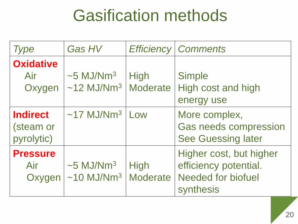
Gasification methods
Type Gas HV Efficiency CommentsOxidative
AirOxygen
~5 MJ/Nm3
~12 MJ/Nm3HighModerate
SimpleHigh cost and high energy use
Indirect (steam or pyrolytic)
~17 MJ/Nm3 Low More complex,Gas needs compressionSee Guessing later
PressureAirOxygen
~5 MJ/Nm3
~10 MJ/Nm3HighModerate
Higher cost, but higher efficiency potential. Needed for biofuel synthesis
20
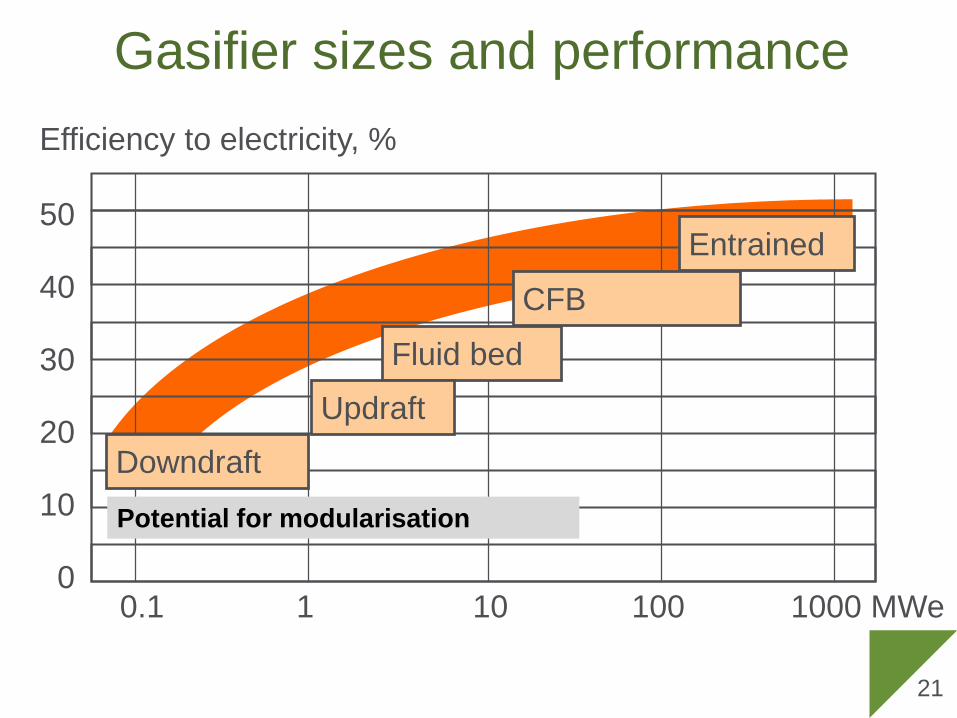
Gasifier sizes and performanceEfficiency to electricity, %
50
40
30
20
10
00.1 1 10 100 1000 MWe
Fluid bed
Updraft
Downdraft
CFB
Entrained
21
Potential for modularisation
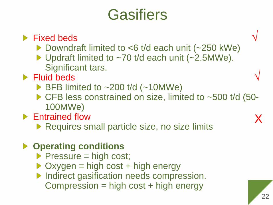
GasifiersFixed beds
Downdraft limited to <6 t/d each unit (~250 kWe)Updraft limited to ~70 t/d each unit (~2.5MWe). Significant tars.
Fluid bedsBFB limited to ~200 t/d (~10MWe)CFB less constrained on size, limited to ~500 t/d (50-100MWe)
Entrained flow Requires small particle size, no size limits
Operating conditionsPressure = high cost; Oxygen = high cost + high energyIndirect gasification needs compression. Compression = high cost + high energy
22
√
√
X

Twin fluid bedAustrian Energy at Guessing Austria. 1.5 t/h; 2 MWeindirect twin fluid bed (allothermal)
> 50000 h operation> 90% availabilityReplicated 2xEconomically viable under Austrian support policies
Replications employed lessons learned from the Guessing plant, so limited modularisation
?
DowndraftBiomass engineering, UK, developed a suite of downdraft gasifiers from 50 to 250 kWe, with simple gas cleaning coupled to an engineProjects up to 2 MWe were supplied based on 8 individual gasifier – gensets coupled togetherThe most common problem was understood to be a failure of the purchasers to control feedstock quality resulting in poor control and dirty gas.
This is close to modularisation. Biomass Engineering currently do not offer biomass gasifiers.
√
24

Biofuels via thermal gasification
The minimum economic size of Fischer Tropsch is widely considered to be 20,000 bbl/day or nearly 1 million t/y biofuels requiring nearly 5 million t/y biomass.
There are several proprietary FT processes. Designs will depend on scale, syngas composition, contaminants and product spectrum
Commercial plants will be purpose designed and built and a modular approach seems unlikely X

Capital costs
0
2000
4000
6000
8000
10000
12000
14000
16000
0 2 4 6 8 10 12
Small pyrolysis + gasification + large FT
Small gasification + small FT
Biomass input million dry t/y
Capital cost, million € 2008
Large gasification + FT
Small FT unproven but developing
Large gasification not proven
Small multiple pyrolysis & large FT -proven
(√)

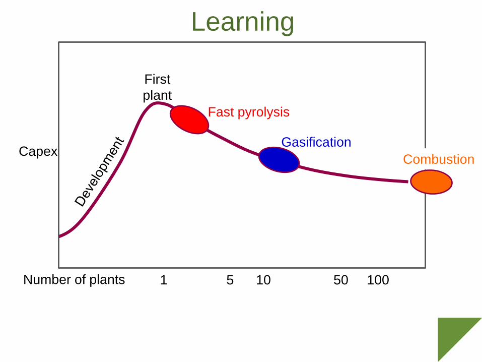
Learning
Number of plants
Capex
1 5 10 50 100
First plant
Learning
Number of plants
Capex
First plant
1 5 10 50 100
Fast pyrolysis
GasificationCombustion

Learning
Number of plants
Capex
First plant
1 5 10 50 100
Fast pyrolysis
GasificationCombustion
ModularisationPotential Some Existing
Modularisation depends on technology maturity, scale of process, and complexity of process
Modularisation conclusionsThe attraction is economic, logistical and operational.Bioenergy is challenging because of the interactions and dependencies between feed, technology and product which can inhibit modularisationModularisation is most likely for small to medium size plantsA sufficiently mature technology is needed for modularisation. Technologies not (yet) optimised are less likely to benefitModularisation offers economic and operational benefits of multiple units if appropriate circumstances arise, but should be compared with economies of scaleSmaller scale modules are more likely to be attractiveModularisation offers the potential for significantly enhanced turn down capability enabling processes to better match demand, but economics are important.
30

Thank you


