Modulation format identification enabled by the digital frequency-offset loading technique for hitless coherent transceiver
SONGNIAN FU,1 ZUYING XU,1 JIANING LU,1,2,* HEXUN JIANG,1 QIONG WU,1 ZHOUYI HU,2 MING TANG,1 DEMING LIU,1 AND CALVIN CHUN-KIT CHAN
2 1Wuhan National Lab for Optoelectronics (WNLO), and School of Optics and Electronic Information, Huazhong University of Science and Technology, Wuhan, 430074, China 2Department of Information Engineering, The Chinese University of Hong Kong, Shatin, Hong Kong *[email protected]
1. Cisco Visual Networking Index, Forecast and Methodology, 2013–2018. [Online] Available at (http://www. cisco.com/en/US/solutions/collateral/ns341/ns525/ns537/ns705/ns827/white_paper_c11–481360.pdf).
2. I. Tomkos, S. Azodolmolky, J. Sole-Pareta, D. Careglio, and E. Palkopoulou, “A tutorial on the flexible optical networking paradigm: state of the art, trends, and research challenges,” Proc. IEEE 102(9), 1317–1337 (2014).
3. H. Khodakarami, B. Pillai, B. Sedighi, and W. Shieh, “Flexible Optical Networks: An Energy Efficiency Perspective,” J. Lightwave Technol. 32(21), 3356–3367 (2014).
4. Q. Zhuge, M. Morsy-Osman, X. Xu, M. Chagnon, M. Qiu, and D. V. Plant, “Spectral efficiency-adaptive optical transmission using time domain hybrid QAM for agile optical networks,” J. Lightwave Technol. 31(15),2621–2628 (2013).
5. Z. Zhang and C. Li, “Hitless Multi-rate Coherent Transceiver,” in Proceedings of Signal Processing in Photonic Communications (2015), paper SpS3D.2.
6. M. Xiang, Q. Zhuge, M. Qiu, X. Zhou, F. Zhang, M. Tang, D. Liu, S. Fu, and D. V. Plant, “Modulation formatidentification aided hitless flexible coherent transceiver,” Opt. Express 24(14), 15642–15655 (2016).
7. V. N. Rozental and D. A. Mello, “Hitless Rate Switching for Dynamically Reconfigurable Optical Systems,” IEEEPhotonics J. 7(2), 1–9 (2015).
8. K. Roberts and C. Laperle, “Flexible transceivers,” in Proceedings of European Conference and Exposition on Optical Communications (2012), paper We.3.A.3.
9. M. Xiang, Q. Zhuge, M. Qiu, X. Zhou, M. Tang, D. Liu, S. Fu, and D. V. Plant, “RF-pilot aided modulation format identification for hitless coherent transceiver,” Opt. Express 25(1), 463–471 (2017).
10. P. Isautier, J. Pan, R. DeSalvo, and S. E. Ralph, “Stokes space-based modulation format recognition for autonomous optical receivers,” J. Lightwave Technol. 33(24), 5157–5163 (2015).
11. R. Boada, R. Borkowski, and I. T. Monroy, “Clustering algorithms for Stokes space modulation format recognition,” Opt. Express 23(12), 15521–15531 (2015).
12. T. Bo, J. Tang, and C. K. Chan, “Modulation Format Recognition for Optical Signals Using Connected Component Analysis,” IEEE Photonics Technol. Lett. 29(1), 11–14 (2017).
13. R. Borkowski, D. Zibar, A. Caballero, V. Arlunno, and I. T. Monroy, “Stokes space-based optical modulation format recognition for digital coherent receivers,” IEEE Photonics Technol. Lett. 25(21), 2129–2132 (2013).
14. F. N. Khan, Y. Zhou, A. P. T. Lau, and C. Lu, “Modulation format identification in heterogeneous fiber-optic networks using artificial neural networks,” Opt. Express 20(11), 12422–12431 (2012).
15. F. N. Khan, K. Zhong, W. H. Al-Arashi, C. Yu, C. Lu, and A. P. T. Lau, “Modulation format identification in coherent receivers using deep machine learning,” IEEE Photonics Technol. Lett. 28(17), 1886–1889 (2016).
16. J. Liu, Z. Dong, K. P. Zhong, A. P. T. Lau, C. Lu, and Y. Lu, “Modulation format identification based on received signal power distributions for digital coherent receivers,” in Proceedings of OFC (2014), paper Th4D.3.
17. G. Liu, R. Proietti, K. Zhang, H. Lu, and S. J. Ben Yoo, “Blind modulation format identification using nonlinear power transformation,” Opt. Express 25(25), 30895–30904 (2017).
18. Y. Wang, E. Serpedin, P. Ciblat, and P. Loubaton, “Non-data aided feedforward cyclostationary statistics based carrier frequency offset estimators for linear modulations,” in Proc. GLOBECOM’01 (2001), pp. 1386–1390.
19. M. Selmi, Y. Jaouën, P. Ciblat, and B. Lankl, “Accurate digital frequency offset estimator for coherent PolMux QAM transmission systems,” in Proc. ECOC’09 (2009), paper P3.08.
20. Z. Xiao, S. Fu, S. Yao, M. Tang, P. Shum, and D. Liu, “ICI Mitigation for Dual-Carrier Superchannel Transmission Based on m-PSK and m-QAM Formats,” J. Lightwave Technol. 34(23), 5526–5533 (2016).
21. J. Lu, X. Li, S. Fu, M. Luo, M. Xiang, H. Zhou, M. Tang, and D. Liu, “Joint carrier phase and frequency-offset estimation with parallel implementation for dual-polarization coherent receiver,” Opt. Express 25(5), 5217–5231 (2017).
22. F. Xiao, J. Lu, S. Fu, C. Xie, M. Tang, J. Tian, and D. Liu, “Feed-forward frequency offset estimation for 32-QAM optical coherent detection,” Opt. Express 25(8), 8828–8839 (2017).
23. M. Oerder and H. Meyr, “Digital Filter and Square Timing Recovery,” IEEE Trans. Commun. 36(5), 605–612 (1988).
24. T. M. Schmidl and D. C. Cox, “Robust frequency and timing synchronization for OFDM,” IEEE Trans. Commun. 45(12), 1613–1621 (1997).
25. T. Pfau, S. Hoffmann, and R. Noé, “Hardware-efficient coherent digital receiver concept with feedforward carrier recovery for M-QAM constellations,” J. Lightwave Technol. 27(8), 989–999 (2009).
1. Introduction
To satisfy the ever-increasing capacity requirement of global IP traffic, optical network is evolving from current fixed architecture to future agile one [1–4]. Therefore, hitless coherent transceiver has attracted worldwide research interests, due to its ability to reconfigure the receiver structure to make full use of both bandwidth and capability of various modulation formats, according to the instantaneous traffic requirement and link condition without transmission interruption [5–9]. With hitless line rate variation by the flexible modulation format switching, the total transmission capacity can be improved with less power consumption. For such hitless coherent transceiver, modulation format identification (MFI) is compulsory to reconfigure the digital signal processing (DSP) flow at the receiver-side (Rx) under the condition of modulation format switching [6]. Up to now, the existing solutions of MFI can be divided into two categories. The first type relies on features of standard quadrature amplitude modulation (QAM) formats [10–17]. For example, MFI is achieved by mapping the signal to the Stokes space [10–13]. Consequently, MFI can be realized by identifying number of clusters or other statistics in Stokes space. Meanwhile, power distribution of constellation after adaptive equalization is analyzed to recognize the modulation format [15,16]. In [17], a MFI based on the nonlinear power transformation is reported. Those MFI solutions are blind, but they cannot be easily extended to more advanced modulation formats, such as time domain hybrid-QAM [4] and set-partitioning (SP)-QAM. Furthermore, they are unable to track fast block-by-block modulation format switching, because the realization of single accurate MFI needs a long averaging length of symbols. Sometimes such a kind of MFI is implemented with machine learning or neural network method [13, 15], which needs a complicated training process or huge and complex calculation. As a result, such a kind of MFI may be not suitable for hitless coherent transceiver. The other kind of MFI is a data-aided (DA) method, which employs either training symbols [6] or sub-carrier pilot [9] to assist the MFI. By this method, fast modulation format switching with only 6400 symbols [6] and 2048 symbols [9] can be achieved. Although those MFIs enable fast tracking of modulation format change, the spectrum efficiency (SE) is sacrificed. Another disadvantage is that such a kind of MFI is bundled with
adaptive equalization and/or carrier phase recovery (CPR), which limits the DSP flexibility. To the best of our knowledge, no blind and fast MFI without SE reduction has been ever demonstrated.
In this paper, we propose a blind and fast MFI enabled by digital frequency-offset (FO) loading technique for hitless coherent transceiver. During the generation of transmission data block, modulation format information is encoded to the artificial-induced FO distribution during the DSP at the transmitter side (Tx), according to the encoding table. At the Rx, fast Fourier transform based FO estimation (FFT-FOE) is adopted after constant modulus algorithm (CMA) pre-equalization to obtain the FO distribution of individual data block, in order to realize blind and fast MFI. Thereby, a hitless coherent transceiver supporting fast modulation format switching with block size of only 2048 symbols is experimentally demonstrated.
2. Operation principle
2.1 Modulation format encoding by Digital FO loading technique
To realize blind and fast MFI for hitless flexible transceiver, we propose to encode the modulation format information to the FO distribution of individual data block. Each data block is divided into 4 parts with the equal length. We can implement artificial FO loading to each part of the data block during the data generation at the Tx. If a FO value is introduced to a data part, the information of “1” is coded. Otherwise, it is encoded as “0” without the digital FO loading. Therefore, 4-bit modulation format information can be encoded to a specific data block. Table 1 shows an example of encoding table with 4-bit information. Please note that the coding sequence “0000” or “1111” cannot be distinguished at the Rx. Therefore, 24-1 = 15 different modulation formats can be identified. In our next investigation, we encoded the format information for every 2048 data symbol. Thus, individual FO is loaded to every 512 data symbols with 1-bit information.
Table 1. Example of modulation format encoding given 4-bit information
0000: BPSK 0001: QPSK
0010: 8QAM 0011: 16QAM
0100~0111: High level QAM
1000~1011: Time-domain hybrid QAM
1100~1110: Multi-dimensional formats
The digital FO loading technique is accurate and easy to be realized. At the Tx, we implement the digital FO loading to every 512 symbols during the data generation of ( )t k . For
each data sequence with a length of 512 symbols, we conduct the FO loading in the digital domain using Eq. (1):
( ) ( ) exp( ) 0,1, 2...511t k m k j k kω= ⋅ Δ = (1)
where ( )m k is the initial data symbol. ωΔ is the angular FO to be loaded. If this part of data
is encoded to “1”, 2
=
f
symbol rate
πω ⋅ ΔΔ is set, where fΔ is the predetermined and optimized
FO. Otherwise, =0ωΔ is chosen.
2.2 FFT-FOE based modulation format identification
At the Rx, after the correct frame synchronization and CMA equalization, the MFI is realized with four times FOE for a specific data block by the FFT-FOE [18,19]. For the traditional
FFT-FOE, the frequency estimation f̂Δ is given under the condition of the maximization of
the periodogram 4 ( )r k as
1
ˆ4 2
ˆ 1/2 0
1ˆ arg max ( )4
Nj fTk
f T k
f r k e π−
− Δ
Δ < =
Δ = (2)
where ( )r k is the kth received symbol, T is the symbol duration. ˆ 1/ 2
arg max (.)f TΔ <
represents the
operation of searching the f̂Δ within the range of [ ]1/ 2 , 1/ 2T T− + which maximizes the
value of function (.). Equation (2) leads to searching the intensity peak in the discrete-frequency spectrum of 4 ( )r k which can be obtained by the FFT technique [18]. Then the location of
intensity peak within the discrete-frequency spectrum represents the FO of the received signal. The FFT-FOE is a non-data-aided (NDA) and fast method with FO acquisition time of only hundreds of symbols. The FFT-FOE is also robust and accurate with a range of [-symbol rate/8,
+ -symbol rate/8] and a FOE resolution of
4 FFT size
symbol rate
⋅. With the help of FFT-FOE, the data
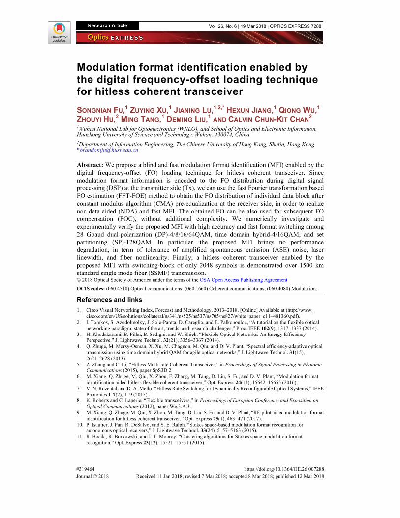
sequence with the FO loading and that without the FO loading can be easily distinguished. Another advantage of the FFT-FOE is that it can function well after the CMA [20]. Although CMA is proposed for the equalization of QPSK format, it has been widely used to conduct pre-equalization for many common formats such as 16-QAM and 64-QAM [21]. Therefore, in our proposed scheme, MFI can be realized before all modulation format-dependent DSP algorithms, including DD-LMS adaptive equalization and CPR. Moreover, the FFT-FOE can be applied to most commonly used modulation formats, such as binary phase shift keying (BPSK), and 4/8/16/64QAM. Please note that the FFT-FOE can also be used for 8-QAM signal, which has a constellation with specific phase distribution. Obviously, we can also use the FFT-FOE to estimate the FO of time domain hybrid-QAM and SP-QAM, because they are extensions of standard QAM. Therefore, we can easily identify the modulation format type by estimating the FO distribution within a single data block using the FFT-FOE. In this work, MFI is obtained for every 2048 symbols. 512 symbols (2048 symbols /4) are used to calculate discrete-frequency spectrum for a single FFT. The discrete-frequency spectrums obtained from X and Y polarizations are added to increase the robustness of FFT-FOE. We choose 512 symbols as the FFT size, leading to the modulation format of the total block size of 2048 symbols to be identified. Please note that longer block size is beneficial for accuracy of the FFT. Thus, longer block size can also be easily supported by our proposed MFI. Please note that, 32-QAM is the only one modulation format which cannot be accurately identified using the proposed MFI within hundreds of symbol, due to its non-rectangular distribution of the constellation points [22]. The discrete-frequency spectrum suffers from severe distortions if the FFT size is only 512 symbols for the 32-QAM signal. Figures 1(a)-1(d) show the discrete-frequency spectrums of 28 Gbaud DP-4QAM, DP-hybrid-4/16QAM, DP-16QAM, and DP-64QAM signals, with 512 symbols per polarization under the optical signal to noise ratio (OSNR) of 9 dB, 12 dB, 12 dB, and 15 dB, respectively. The FO is set to 0 Hz. It can be observed that the FFT-FOE functions well for all those modulation formats with high robustness even if the OSNR is relatively low.
Fig. 1. Discrete-frequency spectrums of (a) DP-4QAM under the condition of OSNR = 9 dB, (b) DP-hybrid-4/16QAM under the condition of OSNR = 12 dB, (c) DP-16QAM under the condition of OSNR = 12 dB, and (d) DP-64QAM under the condition of OSNR = 15 dB. The symbol rate is 28 Gbaud.
0 2048 4096 6144 8192-100
0
100
200
300
400
500
Load
ed F
O (M
Hz)
Symbol index
0 0 0 1 0 0 1 0 0 0 1 1 0 0 0 1
4QAM 8QAM 16QAM 4QAM
code “0”
code “1”
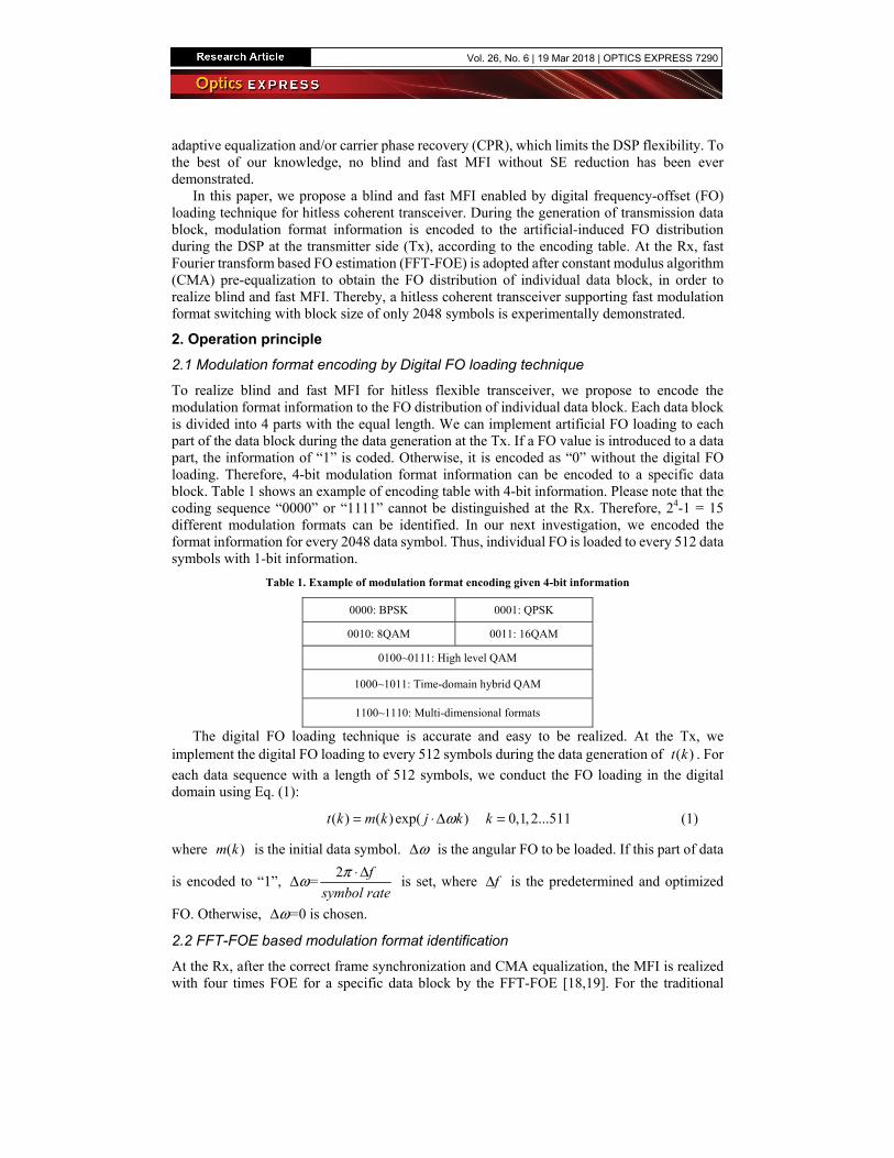
Fig. 2. MFI with the digital FO loading of 200MHz, including discrete-frequency spectrum obtained by the FFT with coding “0” or “1”.
The mapping process between the modulation format information and the encoded bit can be referred from Table 1, after we obtain the FOE value for every 512 symbols using the FFT-FOE. For a data block of 2048 symbols, we can totally obtain 4 discrete FO values. Then, we identify the maximum FO and the minimum FO within those 4 FO values. The average value between the maximum FO and the minimum FO is set as the threshold for the purpose of decoding. If a FO value is lower than such threshold, the code is “0”. Otherwise it would be “1”. Figure 2 illustrates the distribution of the loaded FO over 8192 symbols. The encoded bits ‘0001’, ‘0010’ and ‘0011’ represent 4QAM, 8QAM, and 16QAM used for individual blocks, respectively, according to the encoding table in hand. The inset of Fig. 2 shows the discrete-frequency spectrum obtained by the FFT with coding “0” (blue) or “1” (red). After the modulation format information is obtained, we can reconfigure the parameters of the following DD-LMS equalization, CPR, de-mapping and decoding. The obtained FO value can be also used for FOC, without additional complexity. In comparison with recently proposed MFI based on the FFT [17], our blind MFI can be applied to specific modulation formats such as SP-QAM or hybrid-QAM, due to its essential coding principle. Arbitrary modulation format information can be represented by a 4-bit code sequence, which is introduced to the FO of the signal to be transmitted.
Fig. 3. (a) Experimental setup of the proposed MFI aided hitless coherent transceiver, the schematics of the offline DSP in the (b) transmitter and (c) receiver. (PBS: polarization beam splitter, PBC: polarization beam combiner, AOM: acousto-optic modulator. PC: polarization controller.)
To verify the feasibility of the proposed MFI aided hitless coherent transceiver, we conduct simulations and experiments for a 28-Gbaud coherent transmission system, as shown in Fig. 3. In the Tx offline DSP, the modulation format is assigned by a rate change controller. After differential encoding and mapping, 200 MHz FO is pre-loaded to individual data block, according to Table 1. Then, the arbitrary waveform generator (AWG, Keysight M9502A) provides 28 Gbaud electrical signals to I/Q modulator. Meanwhile, an external cavity laser (ECL) with 100-kHz linewidth is used as optical source. The transmitter output is amplified and launched into a re-circulating fiber loop. The loop contains 75-km standard single mode fiber (SSMF) and an Erbium-doped fiber amplifier (EDFA). The OSNR of signal is monitored by optical spectrum analyzer (OSA, YOKOGAWA AQ6370C). At the Rx, after the coherent detection using another ECL, the signal is captured and digitized by 80 GSa/s digital sampling oscilloscope (Lecroy, Labmaster10-36Zi-A). The Rx offline DSP is also shown in Fig. 3(c). After chromatic dispersion compensation, down sampling to 2 samples per symbol, we conduct the timing recovery including the clock recovery [23] and the frame synchronization. Correct frame synchronization between the transmitter and the receiver is compulsory for the successful implementation of the proposed MFI technique. The frame synchronization method can be achieved by the Schmidt & Cox algorithm [24], where training symbols at the beginning of each frame are used for the purpose of frame synchronization at the receiver side. Before the digital equalization, frame synchronization is realized by two identical patterns consecutively and the timing metric calculation of the received signals. After the CMA pre-equalization, the proposed MFI is performed. Then, the obtained modulation format information is used to direct subsequent DSP flow. For the digital equalization, four 15-taps fractionally-spaced (Ts/2) finite impulse-response (FIR) filters arranged in a butterfly structure are employed for the purpose of polarization division de-multiplexing and differential group delay (DGD) mitigation. Those FIR filters have been pre-converged by the CMA before the MFI. After the MFI is conducted, the final equalization is realized by the DD-LMS algorithm. In the DD-LMS loop, the carrier recovery includes the FOC using the obtained FO value from MFI and the CPR using the BPS method [25]. The decision principles of DD-LMS and BPS can be reconfigured by the MFI information. Finally, BER is counted after de-mapping and decoding.
3.1 Simulations results
Firstly, we carry out numerical investigation of the laser linewidth tolerance under the scenario of back-to-back (B2B) transmission and the tolerance of fiber nonlinearity with our proposed
MFI. Figure 4(a) shows the OSNR penalty at BER of -31 10× as a function of linewidth and symbol period product for DP-4QAM, DP-hybrid 4/16QAM, DP-16QAM and DP-64QAM. The reference case is a transmission system without digital FO loading. We observe that, the penalty due to the digital FO loading is negligible, in comparison with the reference. Then, we investigate the fiber nonlinearity tolerance by testing the transmission performance with respect to the launch powers for DP-8QAM, SP-128QAM, DP-16QAM and DP-64QAM signals after 2640 km, 2120 km, 1840 km, and 520 km SSMF transmissions, as shown in Fig. 4(b). Again, we observe little performance difference between the systems with and without the FO loading. Those results indicate that the proposed MFI does not degrade the tolerance of both laser linewidth and fiber nonlinearity.
-6 -4 -2 0 2 4 6
0.01
0.02
0.03
0.04
0.05
0.06
0.07
BE
R
Launch Power (dBm)
With introduced FO Reference With introduced FO Reference With introduced FO Reference With introduced FO Reference
1E-7 1E-6 1E-5 1E-4 1E-30.0
0.5
1.0
1.5
2.0
OS
NR
pen
alt
y (
dB
)
With introduced FO Reference
With introduced FO Reference
With introduced FO Reference
With introduced FO Reference
} DP-64QAM
DP-16QAM
DP-Hybrid 4/16QAM
DP-4QAM
TsυΔ ⋅
}
}
}
}DP-64QAM
DP-16QAM
SP-128QAM
DP-8QAM
}
}
}(a) (b)
Fig. 4. (a) Laser linewidth tolerance of DP-4QAM, DP-hybrid 4/16QAM, DP-16QAM, and DP-64QAM under the scenario of B2B transmission. (b) BER versus launch power for DP-8QAM, SP-128QAM, DP-16QAM, and DP-64QAM after 2640 km, 2120 km, 1840 km and 520 km SSMF transmission, respectively.
3.2 Experimental results
0 500 1000 1500 2000 2500 3000 3500
0.0
0.2
0.4
0.6
BE
R
Loaded FO (MHz)
Fig. 5. BER as a function of the digitally loaded FO value for DP-16QAM signals after 1500 km SSMF transmissions.
The specific FO value to be digitally loaded is experimentally optimized. If the loaded FO value is too small, it is challenging to distinguish the coding “1” with digital FO loading and coding “0” without loading, because there may be FO jitter and laser induced drifting. Moreover, it should be larger than the estimation resolution of the FFT-FOE, which is determined by the used FFT size [20]. On the other hand, if the loaded FO value is too large, it would bring two problems. Firstly, if the total FO of the signal (consisting of the loaded FO and the FO induced by lasers) is beyond the range of [-symbol rate/8, + symbol rate/8] for the FFT-FOE method [21], the transmission is interrupted. Secondly, high loaded FO value may raise the non-flat frequency responses of the electronic devices. Therefore, we first experimentally investigate the impact of the loaded FO value on the system performance.
Figure 5 shows the relationship between BER and the loaded FO value after 1500 km SSMF transmission for DP-16QAM. When the loaded FO value is smaller than 200 MHz, the BER performance almost keeps unchanged. However, the BER performance degrades as the loaded FO value further increases due to non-flat frequency responses. When the loaded FO value is set to 3.5 GHz, the BER is terribly high, indicating of transmission interruption. This is because the range of FFT-FOE is limited to [-3.5 GHz, + 3.5 GHz] for 28 Gbaud signals. Taken both the MFI accuracy and system performance into account, the loaded FO value of 200 MHz is preferred and chosen in our next experiments.
10 12 14 16 18 20 22 24 26 28 30OSNR (dB)
Theory With loaded FO Reference
1E-3
1E-2
1E-1
BER=2E-2B
ER
DP-4QAM
SP-128QAM
DP-16QAMDP-64QAM
DP-Hybrid-4/16QAM
Fig. 6. B2B performance for DP-4QAM, SP-128QAM, DP-16QAM, DP-hybrid-4/16QAM, and DP-64QAM.
12 14 16 18 20 22 24 26 28 30
0.0
0.2
0.4
0.6
0.8
1.0
Pro
bab
ility
of
corr
ect
iden
tifi
cati
on
OSNR(dB)
0 150 300 450 600 750 900 1050 1200 1350 1500
0.0
0.2
0.4
0.6
0.8
1.0
Pro
bab
ility
of
co
rrect
iden
tifi
cati
on
Transmission distance (km)
DP-64QAMDP-16QAM
DP-64QAM DP-16QAM
(a) (b)
Power distributed based MFI
Proposed MFI
Stokes based MFI
Power distributed based MFI
Proposed MFI
Stokes based MFI
Fig. 7. (a) Correct probability of MFIs versus OSNR under the scenario of B2B transmission. (b) Correct probability of MFIs versus the SSMF transmission distance. “Circle”: DP-64QAM, “Square”: DP-16QAM.
We start to experimentally evaluate the B2B performance, as shown in Fig. 6. The theoretical curves and the curves of transmission without digital FO loading are presented for the purpose of comparison. Almost the same performance between the systems with and without digital FO loading is observed. Thus, the proposed FO loading technique doesn’t worsen the capability of ASE noise tolerance. Next, we evaluate the probability of correct identification for DP-16/64QAM, using the proposed MFI. Both the k-means clustering based Stokes MFI [11] and the distributed power based MFI [16] are used for comparison. For each case, we carry out 1000 times independent MFI. As shown in Fig. 7(a), due to the strong robustness of FFT-FOE, the accuracy of our proposed MFI is much better than other two MFIs. The correct probability of our proposed MFI for DP-64QAM starts to decrease, when the OSNR is below 13 dB. Please note that the required OSNR of DP-64QAM is higher than 21 dB at BER of -22 10× . As for the DP-16QAM, there is no MFI error with the proposed MFI. Meanwhile, the relationship between the correct probability of MFI and SSMF transmission distance is shown in Fig. 7(b). Our proposed MFI still remarkably outperforms other MFIs. Finally, we verify that the proposed digital FO loading technique is able to support a hitless coherent receiver with fast block-by-block modulation format switching. We conduct 1500 km SSMF transmission for the interleaved blocks with DP-16QAM, hybrid-4/16QAM and
SP-128QAM and for the interleaved blocks with hybrid-4/16QAM, SP-128QAM and DP-8QAM. Each block contains 2048 symbols. As shown in Fig. 8(a) and 8(c), after the SSMF transmission, the SNR is stable when the modulation formats are switched. Due to the limited number of symbols in our measurement (only 4096 symbols can be used for SNR calculation in a block from both X and Y polarization), there occurs a little fluctuation. As for the same modulation format, the corresponding BERs are stable. Figures 8(b) and 8(d) show the corresponding FO distribution and decoded format information bit sequence of the signals in Figs. 8(a) and 8(c) obtained by the FFT-FOE, respectively. Although the tunable laser (ID Photonics CoBrite-DX4) used in our experiment indeed drifts over time with a unit of MHz/μs, robust MFI performance is observed with a little FO jitter induced by the tunable laser.
1 2 3 4 5 6 7 8 9 10 11 120.000
0.005
0.010
BE
R
Block index
14.5
15.0
15.5
16.0
16.5
0 4096 8192 12288 16384 20480 245760.0
5.0E7
1.0E8
1.5E8
2.0E8
2.5E8
3.0E8
3.5E8
4.0E8
4.5E8
Blo
ck-b
y-b
loc
k es
tim
ate
d F
O (
Hz)
Symbol index
1 2 3 4 5 6 7 8 9 10 11 12
0.005
0.010
0.015
0.020
0.025
BE
R
Block index
14.0
14.5
15.0
15.5
16.0
S
NR
(dB
)
0011:DP-16QAM
1100:SP-128QAM
1001:DP-Hybrid-4/16QAM
0011 1100 10010011 1100 1001
0011 1100 10010011 1100 1001
~2
00
MH
z
Benchmark FO induced by lasers
Threshold
Laser FO jitter
(a) (b)
(c)
SN
R (d
B)
0010:DP-8QAM
1100:SP-128QAM
1001:DP-Hybrid-4/16QAM
0 4096 8192 12288 16384 20480 245760.0
5.0E7
1.0E8
1.5E8
2.0E8
2.5E8
3.0E8
3.5E8
4.0E8
Blo
ck-
by
-blo
ck
es
tim
ated
FO
(H
z)
Symbol index
0010 10011100 0010 1001
1100 0010 10011100 0010 1001
~2
00
MH
z
Benchmark FO induced by lasers
Threshold
Laser FO jitter
(d)1100
Fig. 8. (a) BER and SNR versus block index for the interleaved DP-16QAM, hybrid-4/16QAM and SP-128QAM. (b) Corresponding FO distribution of signals in (a). (c) BER and SNR versus block index for interleaved hybrid-4/16QAM, SP-128QAM and DP-8QAM. (d) Corresponding FO distribution of signals in (c).
4. Conclusions
We propose a blind and fast MFI enabled by the digital FO loading technique for hitless flexible transceiver. The proposed MFI is numerically investigated and experimentally verified with high accuracy and fast modulation format switching among 28 Gbaud dual-polarization (DP)-4/8/16/64QAM, time domain hybrid-4/16QAM, and SP-128QAM. In particular, the system performance in term of tolerance of amplified spontaneous emission (ASE) noise, laser linewidth, and fiber nonlinearity, keep the same as that without the proposed MFI being used. Finally, over 1500 km SSMF link, a hitless flexible transceiver with switching-block of only 2048 symbols is demonstrated.
Funding
National Natural Science Foundation of China (61575071) and 863 High Technology Plan (2015AA015502),


![interoperability.blob.core.windows.netinteroperability.blob.core.windows.net/files/MS... · Web view[MS-OFFMACRO2]: Office Macro-Enabled File Format Version 2. Intellectual Property](https://static.documents.pub/doc/80x56/5a72c65c7f8b9aa7538dee12/a-doc-fileaa-web-viewms-offmacro2-office-macro-enabled-file-format.jpg)

![Introduction - interoperability.blob.core.windows.netinteroperability.blob.core.windows.net/...160914.docx · Web view[MS-OFFMACRO2]: Office Macro-Enabled File Format Version 2.](https://static.documents.pub/doc/80x56/5af3c60a7f8b9a92718c917d/introduction-viewms-offmacro2-office-macro-enabled-file-format-version-2-intellectual.jpg)

![interoperability.blob.core.windows.netinteroperability.blob.core.windows.net/files/MS-OFFMA… · Web view[MS-OFFMACRO]: Office Macro-Enabled File Format. Intellectual Property Rights](https://static.documents.pub/doc/80x56/5b2d6c007f8b9a55208b4f98/-web-viewms-offmacro-office-macro-enabled-file-format-intellectual-property.jpg)
![[MS-OFFMACRO]: Office Macro-Enabled File FormatMS-OFFMACRO].pdf · Office Macro-Enabled File Format ... [MS-OFFMACRO]: Office Macro-Enabled File Format Intellectual Property Rights](https://static.documents.pub/doc/80x56/5ae0708b7f8b9a6e5c8d682d/ms-offmacro-office-macro-enabled-file-format-ms-offmacropdfoffice-macro-enabled.jpg)

![interoperability.blob.core.windows.netinteroperability.blob.core.windows.net/files/MS...Web view[MS-OFFMACRO]: Office Macro-Enabled File Format. Intellectual Property Rights Notice](https://static.documents.pub/doc/80x56/5b2d6c007f8b9a55208b4f54/viewms-offmacro-office-macro-enabled-file-format-intellectual-property-rights.jpg)


