Modulation-free laser frequency stabilization to a saturated sub-Doppler spectral line in a transversal magnetic field Sho Okubo, Kana Iwakuni, Taro Hasegawa n Department of Physics, Keio University, Kanagawa 223-8522, Japan article info Article history: Received 8 March 2012 Received in revised form 27 April 2012 Accepted 4 June 2012 Available online 22 June 2012 Keywords: Saturation spectroscopy Laser frequency stabilization Zeeman shift abstract We demonstrate frequency stabilization of a modulation-free laser to a saturated absorption spectral line of atoms in a transversal magnetic field. This stabilization scheme has been proposed for wide capture range in comparison with the dichroic atomic vapor laser lock (DAVLL) scheme and demonstrated for a Doppler-broadened spectral line in J. Opt. Soc. Am. B, 26, 1216 (2009). In this paper, a 1083-nm external-cavity laser diode is frequency-stabilized to the sub-Doppler spectral line of helium transition (2 3 S 1 , m J ¼ 022 3 P 0 ). Even though the error signal shape strongly depends on the pump beam polarization, the stabilized frequency is expected to be insensitive to the pump beam polarization. & 2012 Elsevier B.V. All rights reserved. 1. Introduction Stabilization of continuous-wave laser frequency to optical transitions of atoms, ions, and molecules is a basic technique for high resolution spectroscopy, optical frequency measurement,and laser cooling and trapping. In particular, saturated absorption spectroscopy of sub-Doppler resolution is employed in order to stabilize the laser frequency with small uncertainty. A number of schemes to provide frequency discrimination signals for modula- tion-free frequency stabilization are proposed. Examples are those based on polarization spectroscopy [1–3], spectroscopy in longitudinal magnetic field known as the dichroic atomic vapor laser lock (DAVLL) [4], and spectroscopy in transversal magnetic field (transversal DAVLL (t-DAVLL)) [5]. These schemes can be employed for either of Doppler-broadened spectral lines or saturated sub-Doppler lines. In fact, the DAVLL has been demon- strated at first for the Doppler-broadened line of rubidium [4], and later for the saturated spectral lines [6–8]. The t-DAVLL scheme has also been demonstrated with the Doppler-broadened line (5d 2 D 3=2 –6p 2 P 1=2 of Ba þ at 650 nmÞ. The t-DAVLL scheme has an advantage over the DAVLL scheme because the former has wider capture range than the latter [5]. As far as we know, however, the t-DAVLL has not been carried out with the sub- Doppler spectral lines. In the DAVLL, the error signal for the stabilization feedback corresponds to the absorption (imaginary part of the electric suscep- tibility), which has the dependence of 1=d 2 in the far-detuned limit for the complex Lorentzian spectral line shape, where d is the detuning of the radiation frequency from the resonance. On the other hand in the t-DAVLL scheme, the error signal corresponds to the phase shift of the radiation associated with dispersion (real part of the electric susceptibility), which has the dependence of long-tailed 1=d in the far-detuned limit for the complex Lorentzian. Therefore, the robustness with the t-DAVLL scheme may be more remarkable in Lorentzian-broadened spectral lines such as those obtained by sub-Doppler saturation spectroscopy than in Doppler- broadened lines. In this paper, we obtain dispersive error signals for the laser frequency stabilization by the t-DAVLL scheme with the saturated spectral line of the 2 3 S 1 –2 3 P 0 transition of metastable helium at 1083 nm. The error signals are recorded for four linear polariza- tions of the pump beam, and it turns out that the error signal shape is sensitive to the pump beam polarization. The error signal is, however, always an odd function of d regardless of the pump beam polarization, so that the laser frequency stabilized with this error signal is expected to be insensitive to the pump beam polarization. An external-cavity laser diode (ECLD) is stabilized using this error signal, and the uncertainty of the laser frequency is suppressed. 2. Error signal by the t-DAVLL scheme with the saturated spectral line The t-DAVLL signal of the saturated spectral line can be obtained by introducing a counterpropagating pump beam in addition to the probe beam in the setup of Fig. 1 in [5]. Fig. 1 shows the experimental setup to obtain dispersive error signals Contents lists available at SciVerse ScienceDirect journal homepage: www.elsevier.com/locate/optcom Optics Communications 0030-4018/$ - see front matter & 2012 Elsevier B.V. All rights reserved. http://dx.doi.org/10.1016/j.optcom.2012.06.007 n Corresponding author. þ81 45 566 1801; fax: þ81 45 566 1672. E-mail address: [email protected] (T. Hasegawa). Optics Communications 285 (2012) 4107–4111
Transcript
Optics Communications 285 (2012) 4107–4111
Contents lists available at SciVerse ScienceDirect
Optics Communications
0030-40
http://d
n Corr
E-m
journal homepage: www.elsevier.com/locate/optcom
Modulation-free laser frequency stabilization to a saturated sub-Dopplerspectral line in a transversal magnetic field
Sho Okubo, Kana Iwakuni, Taro Hasegawa n
Department of Physics, Keio University, Kanagawa 223-8522, Japan
We demonstrate frequency stabilization of a modulation-free laser to a saturated absorption spectral
line of atoms in a transversal magnetic field. This stabilization scheme has been proposed for wide
capture range in comparison with the dichroic atomic vapor laser lock (DAVLL) scheme and
demonstrated for a Doppler-broadened spectral line in J. Opt. Soc. Am. B, 26, 1216 (2009). In this
paper, a 1083-nm external-cavity laser diode is frequency-stabilized to the sub-Doppler spectral line of
helium transition (23S1 ,mJ ¼ 0223P0). Even though the error signal shape strongly depends on the
pump beam polarization, the stabilized frequency is expected to be insensitive to the pump beam
polarization.
& 2012 Elsevier B.V. All rights reserved.
1. Introduction
Stabilization of continuous-wave laser frequency to opticaltransitions of atoms, ions, and molecules is a basic technique forhigh resolution spectroscopy, optical frequency measurement,andlaser cooling and trapping. In particular, saturated absorptionspectroscopy of sub-Doppler resolution is employed in order tostabilize the laser frequency with small uncertainty. A number ofschemes to provide frequency discrimination signals for modula-tion-free frequency stabilization are proposed. Examples arethose based on polarization spectroscopy [1–3], spectroscopy inlongitudinal magnetic field known as the dichroic atomic vaporlaser lock (DAVLL) [4], and spectroscopy in transversal magneticfield (transversal DAVLL (t-DAVLL)) [5]. These schemes can beemployed for either of Doppler-broadened spectral lines orsaturated sub-Doppler lines. In fact, the DAVLL has been demon-strated at first for the Doppler-broadened line of rubidium [4],and later for the saturated spectral lines [6–8]. The t-DAVLLscheme has also been demonstrated with the Doppler-broadenedline (5d 2D3=2–6p2P1=2 of Baþ at 650 nmÞ. The t-DAVLL scheme hasan advantage over the DAVLL scheme because the former haswider capture range than the latter [5]. As far as we know,however, the t-DAVLL has not been carried out with the sub-Doppler spectral lines.
In the DAVLL, the error signal for the stabilization feedbackcorresponds to the absorption (imaginary part of the electric suscep-tibility), which has the dependence of 1=d2 in the far-detuned limit
ll rights reserved.
81 45 566 1672.
egawa).
for the complex Lorentzian spectral line shape, where d is thedetuning of the radiation frequency from the resonance. On theother hand in the t-DAVLL scheme, the error signal corresponds tothe phase shift of the radiation associated with dispersion (realpart of the electric susceptibility), which has the dependence oflong-tailed 1=d in the far-detuned limit for the complex Lorentzian.Therefore, the robustness with the t-DAVLL scheme may be moreremarkable in Lorentzian-broadened spectral lines such as thoseobtained by sub-Doppler saturation spectroscopy than in Doppler-broadened lines.
In this paper, we obtain dispersive error signals for the laserfrequency stabilization by the t-DAVLL scheme with the saturatedspectral line of the 23S1–23P0 transition of metastable helium at1083 nm. The error signals are recorded for four linear polariza-tions of the pump beam, and it turns out that the error signalshape is sensitive to the pump beam polarization. The error signalis, however, always an odd function of d regardless of the pumpbeam polarization, so that the laser frequency stabilized with thiserror signal is expected to be insensitive to the pump beampolarization. An external-cavity laser diode (ECLD) is stabilizedusing this error signal, and the uncertainty of the laser frequencyis suppressed.
2. Error signal by the t-DAVLL scheme with the saturatedspectral line
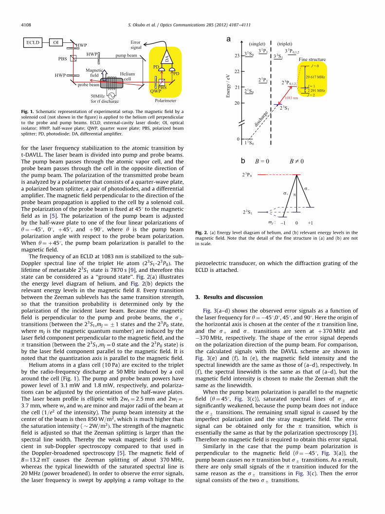
The t-DAVLL signal of the saturated spectral line can beobtained by introducing a counterpropagating pump beam inaddition to the probe beam in the setup of Fig. 1 in [5]. Fig. 1shows the experimental setup to obtain dispersive error signals
splitter; PD, photodiode; DA, differential amplifier.
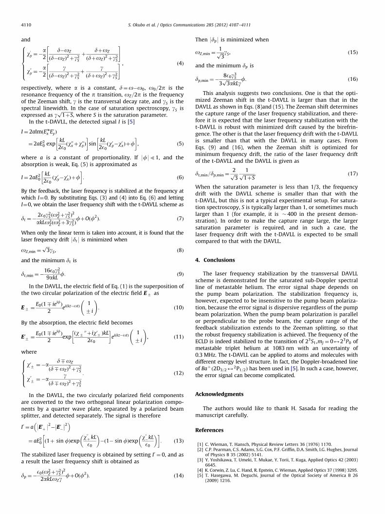
Fig. 2. (a) Energy level diagram of helium, and (b) relevant energy levels in the
magnetic field. Note that the detail of the fine structure in (a) and (b) are not
in scale.
S. Okubo et al. / Optics Communications 285 (2012) 4107–41114108
for the laser frequency stabilization to the atomic transition byt-DAVLL. The laser beam is divided into pump and probe beams.The pump beam passes through the atomic vapor cell, and theprobe beam passes through the cell in the opposite direction ofthe pump beam. The polarization of the transmitted probe beamis analyzed by a polarimeter that consists of a quarter-wave plate,a polarized beam splitter, a pair of photodiodes, and a differentialamplifier. The magnetic field perpendicular to the direction of theprobe beam propagation is applied to the cell by a solenoid coil.The polarization of the probe beam is fixed at 451 to the magneticfield as in [5]. The polarization of the pump beam is adjustedby the half-wave plate to one of the four linear polarizations ofy¼�451, 01, þ451, and þ901, where y is the pump beampolarization angle with respect to the probe beam polarization.When y¼ þ451, the pump beam polarization is parallel to themagnetic field.
The frequency of an ECLD at 1083 nm is stabilized to the sub-Doppler spectral line of the triplet He atom ð23S1-23P0Þ. Thelifetime of metastable 23S1 state is 7870 s [9], and therefore thisstate can be considered as a ‘‘ground state’’. Fig. 2(a) illustratesthe energy level diagram of helium, and Fig. 2(b) depicts therelevant energy levels in the magnetic field B. Every transitionbetween the Zeeman sublevels has the same transition strength,so that the transition probability is determined only by thepolarization of the incident laser beam. Because the magneticfield is perpendicular to the pump and probe beams, the s7
transitions (between the 23S1,mJ ¼ 71 states and the 23P0 state,where mJ is the magnetic quantum number) are induced by thelaser field component perpendicular to the magnetic field, and thep transition (between the 23S1,mJ ¼ 0 state and the 23P0 state) isby the laser field component parallel to the magnetic field. It isnoted that the quantization axis is parallel to the magnetic field.
Helium atoms in a glass cell (10 Pa) are excited to the tripletby the radio-frequency discharge at 50 MHz induced by a coilaround the cell (Fig. 1). The pump and probe beam powers havepower level of 3.1 mW and 1.8 mW, respectively, and polariza-tions can be adjusted by the orientation of the half-wave plates.The laser beam profile is elliptic with 2ws ¼ 2:5 mm and 2wl ¼
3:7 mm, where ws and wl are minor and major radii of the beam atthe cell (1=e2 of the intensity). The pump beam intensity at thecenter of the beam is then 850 W=m2, which is much higher thanthe saturation intensity (� 2W=m2Þ. The strength of the magneticfield is adjusted so that the Zeeman splitting is larger than thespectral line width. Thereby the weak magnetic field is suffi-cient in sub-Doppler spectroscopy compared to that used inthe Doppler-broadened spectroscopy [5]. The magnetic field ofB¼13.2 mT causes the Zeeman splitting of about 370 MHz,whereas the typical linewidth of the saturated spectral line is20 MHz (power broadened). In order to observe the error signals,the laser frequency is swept by applying a ramp voltage to the
piezoelectric transducer, on which the diffraction grating of theECLD is attached.
3. Results and discussion
Fig. 3(a–d) shows the observed error signals as a function ofthe laser frequency for y¼�451,01, 451, and 901. Here the origin ofthe horizontal axis is chosen at the center of the p transition line,and the sþ and s� transitions are seen at þ370 MHz and�370 MHz, respectively. The shape of the error signal dependson the polarization direction of the pump beam. For comparison,the calculated signals with the DAVLL scheme are shown inFig. 3(e) and (f). In (e), the magnetic field intensity and thespectral linewidth are the same as those of (a–d), respectively. In(f), the spectral linewidth is the same as that of (a–d), but themagnetic field intensity is chosen to make the Zeeman shift thesame as the linewidth.
When the pump beam polarization is parallel to the magneticfield (y¼ 451, Fig. 3(c)), saturated spectral lines of s7 aresignificantly weakened, because the pump beam does not inducethe s7 transitions. The remaining small signal is caused by theimperfect polarization and the stray magnetic field. The errorsignal can be obtained only for the p transition, which isessentially the same as that by the polarization spectroscopy [3].Therefore no magnetic field is required to obtain this error signal.
Similarly in the case that the pump beam polarization isperpendicular to the magnetic field (y¼�451, Fig. 3(a)), thepump beam causes no p transition but s7 transitions. As a result,there are only small signals of the p transition induced for thesame reason as the s7 transitions in Fig. 3(c). Then the errorsignal consists of the two s7 transitions.
Fig. 3. (a-d) Error signals obtained with the saturated sub-Doppler spectral line
for y¼�451, 01, 451, and 901, where y is the angle between the linear polarizations
of pump and probe beams. The values of y are shown in the figure. (e) and
(f) Calculated signals for the DAVLL scheme. In (e), the same values of the
magnetic field intensity and the spectral linewidth as (a–d) are used. In (f), the
same value of the linewidth is used, but the Zeeman shift is chosen to be the same
as the linewidth.
Fig. 4. Error signals with and without the stabilization feedback. The pump beam
polarization is parallel to that of the probe beam (y¼ 01).
S. Okubo et al. / Optics Communications 285 (2012) 4107–4111 4109
When the pump beam polarization is parallel or perpendicularto the pump beam polarization (y¼ 01 or 901, Fig. 3(b) and (d)),the pump beam causes both p and s7 transitions. Hence theerror signal consists of one p transition and two s7 transitions.The signal intensity of the p transition is twice of that of the sþ ors� transition (this ratio is determined by the polarization). Thes7 transitions broaden the frequency discrimination signal up to7370 MHz. The whole lineshape is similar to that obtained bythe Pound–Drever–Hall scheme [10], and the capture range isthereby broadened. Therefore, the error signal with y¼ 01 or 901is more useful for the frequency stabilization than that withy¼7451 because of the wide capture range. It should be notedthat the error signal is an odd function with respect to the centerfrequency regardless of the pump beam polarization, so that thelocking frequency does not depend on the pump beam polariza-tion. Consequently, the stabilized laser frequency is expected tobe insensitive to the pump beam polarization.
As shown in Fig. 3(e) and (f), the DAVLL signals can be used onlywhen the Zeeman shift is comparable with the spectral linewidth. Ifthe Zeeman shift is much larger than the linewidth as in Fig. 3(e),the slope at the origin, at which the laser frequency is to bestabilized, becomes too small to be used as an error signal. In thet-DAVLL, however, the capture range of the error signal can be aswide as the Zeeman shift with a substantially large value of theslope at the origin. Consequently, the practical capture ranges withthe DAVLL and the t-DAVLL are as wide as the spectral linewidthð � 20 MHzÞ and the Zeeman shift ð � 370 MHzÞ, respectively.
The signal of y¼ 01 is indeed used for the stabilization ofthe laser frequency. The signal is fed back to the piezoelectrictransducer of the ECLD (the time constant is about 50 ms, which is
determined by the response of the piezoelectric transducer).Fig. 4 shows the error signals with and without the feedback.The uncertainty of the laser frequency is estimated about 2.5 MHzin free run, and reduces to 0.3 MHz with the feedback.
It has been pointed out that in the DAVLL scheme thetemperature drift causes the polarization drift by birefringenceof optical components such as glass cell windows, resulting thestabilized laser frequency drift [11]. The birefringence causesoffset of the error signal, and then it changes the lock point ofthe laser frequency. By using a simple model, we will discuss thefrequency shift caused by the birefringence drift in both cases oft-DAVLL and DAVLL schemes. In the present model, we assumethe Lorentzian absorption because the saturated spectroscopy isconsidered. In order to simplify the analysis, no effects of theDoppler broadening and fluctuations of the pump beam polariza-tion are considered, and the energy level scheme in Fig. 2 isassumed. Because the sub-Doppler spectral line corresponds tothe reduction of the absorption, it may be accurate to considerthe spectral lines as amplification rather than absorption, butthis only changes the sign of the signal. Detailed analysis may befuture subjects.
First, we derive the laser frequency drift as a function of thebirefringence in the case of t-DAVLL and later of DAVLL. Theelectric field of the probe beam that propagates along z-directionis expressed as
E¼ E0eiðkz�otÞ 1
eif
� �, ð1Þ
where E0 is the amplitude of the laser, o=2p and k are thefrequency and the wavenumber of the laser, respectively. f is thephase shift of the y component of E with respect to the x
component caused by the birefringence drift. The magnetic fieldis applied to x-direction. In the absorption cell, the optical fieldundergoes the absorption and the phase shift, and after the cell,Eq. (1) is modified as
E0 ¼ E0eiðkz�otÞ
expðw00xþ iw0xÞkL
2E0
� �
expðw00yþ iw0yÞkL
2E0þ if
" #0BBBB@
1CCCCA, ð2Þ
where wx,y ¼ wx,y0 �iwx,y
00 is a complex electric susceptibility of theabsorbing atoms, L is the length of the cell, and E0 is the electricconstant. The p (s7 Þ transition is induced by the x (y) componentof the field, so that w0x,y and wx,y
00 are [12]
w0x ¼�ad
d2þg2
S
w00x ¼�ag
d2þg2
S
8>>>><>>>>:
ð3Þ
S. Okubo et al. / Optics Communications 285 (2012) 4107–41114110
and
w0y ¼�a2
d�oZ
ðd�oZÞ2þg2
S
þdþoZ
ðdþoZÞ2þg2
S
" #
w00y ¼�a2
gðd�oZÞ
2þg2
S
þg
ðdþoZÞ2þg2
S
" #8>>>>><>>>>>:
, ð4Þ
respectively, where a is a constant, d¼o�o0, o0=2p is theresonance frequency of the p transition, oZ=2p is the frequencyof the Zeeman shift, g is the transversal decay rate, and gS is thespectral linewidth. In the case of saturation spectroscopy, gS isexpressed as g
ffiffiffiffiffiffiffiffiffiffi1þSp
, where S is the saturation parameter.In the t-DAVLL, the detected signal I is [5]
I¼ 2aImðE0nx E0yÞ
¼ 2aE20 exp
kL
2E0ðw00xþw
00yÞ
� �sin
kL
2E0ðw0y�w
0xÞþf
� �, ð5Þ
where a is a constant of proportionality. If 9f951, and theabsorption is weak, Eq. (5) is approximated as
I¼ 2aE20
kL
2E0ðw0y�w
0xÞþf
� �: ð6Þ
By the feedback, the laser frequency is stabilized at the frequency atwhich I¼0. By substituting Eqs. (3) and (4) into Eq. (6) and lettingI¼0, we obtain the laser frequency shift with the t-DAVLL scheme as
dt ¼�2E0g2
S ðo2Zþg2
S Þ2
akLo2Zðo2
Zþ3g2S ÞfþOðf2
Þ: ð7Þ
When only the linear term is taken into account, it is found that thelaser frequency drift 9dt9 is minimized when
oZ,min ¼ffiffiffi3p
gS, ð8Þ
and the minimum dt is
dt,min ¼�16E0g2
S
9akLf: ð9Þ
In the DAVLL, the electric field of Eq. (1) is the superposition ofthe two circular polarization of the electric field E7 as
E7 ¼E0ð18 ieif
Þ
2eiðkz�otÞ
1
7 i
!: ð10Þ
By the absorption, the electric field becomes
E07 ¼E0ð18 ieif
Þ
2expðw7
00 þ iw07 ÞkL
2E0
� �ei kz�otð Þ
1
7 i
!, ð11Þ
where
w07 ¼�ad8oZ
ðd8oZÞ2þg2
S
w007 ¼�ag
ðd8oZÞ2þg2
S
8>>><>>>:
: ð12Þ
In the DAVLL, the two circularly polarized field componentsare converted to the two orthogonal linear polarization compo-nents by a quarter wave plate, separated by a polarized beamsplitter, and detected separately. The signal is therefore
I0 ¼ a 9E0þ 92� E0��� ��2�
¼ aE20 ð1þ sin fÞexp
w00þ kL
E0
� �� 1� sin fð Þexp
w00�kL
E0
� �� �: ð13Þ
The stabilized laser frequency is obtained by setting I0 ¼ 0, and asa result the laser frequency shift is obtained as
dp ¼�E0ðo2
Zþg2S Þ
2
2akLoZgfþOðf2
Þ: ð14Þ
Then 9dp9 is minimized when
oZ,min ¼1ffiffiffi3p gS, ð15Þ
and the minimum dp is
dp,min ¼�8E0g3
S
3ffiffiffi3p
akLgf: ð16Þ
This analysis suggests two conclusions. One is that the opti-mized Zeeman shift in the t-DAVLL is larger than that in theDAVLL as shown in Eqs. (8)and (15). The Zeeman shift determinesthe capture range of the laser frequency stabilization, and there-fore it is expected that the laser frequency stabilization with thet-DAVLL is robust with minimized drift caused by the birefrin-gence. The other is that the laser frequency drift with the t-DAVLLis smaller than that with the DAVLL in many cases. FromEqs. (9) and (16), when the Zeeman shift is optimized forminimum frequency drift, the ratio of the laser frequency driftof the t-DAVLL and the DAVLL is given as
dt,min=dp,min ¼2ffiffiffi3p
1ffiffiffiffiffiffiffiffiffiffi1þSp : ð17Þ
When the saturation parameter is less than 1/3, the frequencydrift with the DAVLL scheme is smaller than that with thet-DAVLL, but this is not a typical experimental setup. For satura-tion spectroscopy, S is typically larger than 1, or sometimes muchlarger than 1 (for example, it is � 400 in the present demon-stration). In order to make the capture range large, the largersaturation parameter is required, and in such a case, thelaser frequency drift with the t-DAVLL is expected to be smallcompared to that with the DAVLL.
4. Conclusions
The laser frequency stabilization by the transversal DAVLLscheme is demonstrated for the saturated sub-Doppler spectralline of metastable helium. The error signal shape depends onthe pump beam polarization. The stabilization frequency is,however, expected to be insensitive to the pump beam polariza-tion, because the error signal is dispersive regardless of the pumpbeam polarization. When the pump beam polarization is parallelor perpendicular to the probe beam, the capture range of thefeedback stabilization extends to the Zeeman splitting, so thatthe robust frequency stabilization is achieved. The frequency of theECLD is indeed stabilized to the transition of 23S1,mJ ¼ 0223P0 ofmetastable triplet helium at 1083 nm with an uncertainty of0.3 MHz. The t-DAVLL can be applied to atoms and molecules withdifferent energy level structure. In fact, the Doppler-broadened lineof Baþ ð2D3=22
2P1=2Þ has been used in [5]. In such a case, however,the error signal can become complicated.
Acknowledgments
The authors would like to thank H. Sasada for reading themanuscript carefully.
References
[1] C. Wieman, T. Hansch, Physical Review Letters 36 (1976) 1170.[2] C.P. Pearman, C.S. Adams, S.G. Cox, P.F. Griffin, D.A. Smith, I.G. Hughes, Journal
of Physics B 35 (2002) 5141.[3] Y. Yoshikawa, T. Umeki, T. Mukae, Y. Torii, T. Kuga, Applied Optics 42 (2003)
6645.[4] K. Corwin, Z. Lu, C. Hand, R. Epstein, C. Wieman, Applied Optics 37 (1998) 3295.[5] T. Hasegawa, M. Deguchi, Journal of the Optical Society of America B 26
(2009) 1216.
S. Okubo et al. / Optics Communications 285 (2012) 4107–4111 4111
[6] G. Wasik, W. Gawlik, J. Zachorowski, W. Zawadzki, Applied Physics B 75 (2002)613.
[7] T. Petelski, M. Fattori, G. Lamporesi, J. Stuhler, G. Tino, European PhysicalJournal D 22 (2003) 279.
[8] M.L. Harris, S.L. Cornish, A. Tripathi, I.G. Hughes, Journal of Physics B 41(2008) 085401.