Drinking Water Operator Certification Training Module 23: Organics Removal This course includes content dev eloped by the Pennsylvania Department of Environmental Protection Pa. DEP) in cooperation with the following contractors, subcontractors, or grantees: The Pennsylvania State Association of Township Supervisors (PSATS) Gannett Fleming, Inc. Dering Consulting Group Penn State Harrisburg Environmental Training Center
Transcript
Drinking Water Operator Certification Training
Module 23: Organics Removal
This course includes content dev eloped by the Pennsylvania Department of Environmental Protection Pa. DEP) in cooperation with the following contractors, subcontractors, or grantees:
The Pennsylvania State Association of Township Supervisors (PSATS) Gannett Fleming, Inc.
Dering Consulting Group Penn State Harrisburg Environmental Training Center
MODULE 23: ORGANICS REMOVAL
Bureau of Water Supply and Wastewater Management, Department of Environmental Protection Drinking Water Operator Certification Training i
Topical Outline
Unit 1 – Background and Overview of Organics I. Terms and Definitions II. Organic Chemicals
A. Background B. Properties of Organic Compounds C. Sources of Organics D. Problem Organics
III. Control and Treatment Methods
A. Source Control B. Air Stripping C. Adsorption D. Precipitation and Filtration E. Direct Filtration F. Combination of Oxidation and Adsorption G. Reverse Osmosis H. Ion Exchange I. Boiling
MODULE 23: ORGANICS REMOVAL
Bureau of Water Supply and Wastewater Management, Department of Environmental Protection Drinking Water Operator Certification Training ii
Unit 2 – Source Control I. Source Control Overview
A. Definition B. Five Components
II. Monitoring Water Quality
A. Source Water Monitoring B. Water Quality Parameters and Testing C. Predicting Changes
III. Treating Naturally Occurring Organic Material
A. Destratification B. Algicide C. Intake Placement D. Multiple Sources
IV. Minimizing Formation of Compounds During Water Treatment
A. Chlorine Application Point B. Alternative Disinfectants
V. Controlling Chemical Reactions within Transmission Systems VI. Limiting Contaminants Originating from Commercial Activities
A. Industrial B. Wastewater Treatment C. Non-point Sources
MODULE 23: ORGANICS REMOVAL
Bureau of Water Supply and Wastewater Management, Department of Environmental Protection Drinking Water Operator Certification Training iii
Unit 3 – Air Stripping I. Introduction
A. Description of Air Stripping Process B. Constituents Removed by Aeration
II. Aeration Equipment A. Packed Tower Aerators B. Bubble Diffusers C. Tray, Cascade, and Cone Aerators D. Spray Aerators
III. Process Operation and Monitoring A. Gas to Liquid Ratio in Packed Towers B. Inspection C. Cleaning
IV. Common Operating Problems A. Fouling B. Problems Resulting from Fouling C. Excess Aeration D. Packed Tower Incorrect Design Assumptions
V. Monitoring A. Organic Concentration B. Flow Rates C. Exhaust Emissions
VI. Safety and Aeration A. Hazards B. Preventions and Remedies
MODULE 23: ORGANICS REMOVAL
Bureau of Water Supply and Wastewater Management, Department of Environmental Protection Drinking Water Operator Certification Training iv
Unit 4 – Adsorption I. Introduction
A. Description of Adsorption Process B. Activated Carbon
II. Powdered Activated Carbon (PAC)
A. Point of Application B. Dose C. Feed Equipment D. Carbon Contactors E. Operation and Monitoring F. Maintenance G. Common Operating Problems
III. Granular Activated Carbon (GAC) A. GAC Properties B. Equipment Types C. Equipment Properties D. Retrofitting Existing Conventional Filters E. Operation and Monitoring F. Maintenance G. Carbon Regeneration H. Operating Problems I. Biological GAC (BAC)
IV. Safety
Bureau of Water Supply and Wastewater Management, Department of Environmental Protection 1- Drinking Water Operator Certification Training
1
Unit 1 – Background and Overview of Organics
Learning Objectives
• List the four basic elements in organic chemicals.
• Name the four properties of organics that affect their ability to be treated.
• Name the three key methods of control and treatment.
• List other methods that can be used to remove organics from the water.
TERMS AND DEFINITIONS
Bureau of Water Supply and Wastewater Management, Department of Environmental Protection 1- Drinking Water Operator Certification Training
2
Molecular weight—the weight, in grams, of one mole (6.02x10²³ molecules) of a substance.
Polarity—describes the degree to which one segment of a molecule is either positively or negatively charged with respect to another part of the molecular structure. The greater the charge difference, the more polar the molecule.
Volatility—a reflection of the tendency for a substance to be found in the gaseous state at room temperature. This is generally indicated by the boiling point or vapor pressure.
Humic material—compounds produced during the natural chemical and microbial degradation of vegetation.
Halogen—one of a class of elements including chlorine, fluorine, bromine, and iodine.
Halogenated organics—organic compounds containing a halogen.
Synthetic Organic Chemical (SOC)—man-made organic chemical.
Trihalomethane (THM)—one of four halogenated organics that are suspected to increase the risk of cancer.
THM formation potential—a measurement of the potential for a water to form THMs upon chlorination.
Disinfection by-products—trihalomethanes and other halogenated organics produced by the reaction of disinfectants such as chlorine with organics.
ORGANIC CHEMICALS
Bureau of Water Supply and Wastewater Management, Department of Environmental Protection 1- Drinking Water Operator Certification Training
3
Background
The term organics generally refers to the class of chemicals with a molecular structure composed of Carbon (C) and one or more of the following elements:
Hydrogen (H)
Nitrogen (N)
Oxygen (O) Examples of Organics
Methane (CH4)
Acetone (CH3)2CO
Ether (C4H10O)
Acetamide (C2H5NO)
Exceptions
Some simple molecules appear to be organic, but instead they are considered inorganic compounds because of the type of bonding that occurs between the atoms. Examples of those compounds include:
Carbon Monoxide (CO)
Carbon Dioxide (CO2)
Carbonate (CO32-)
Bicarbonate (HCO3-)
Cyanide (CN-)
ORGANIC CHEMICALS
Bureau of Water Supply and Wastewater Management, Department of Environmental Protection 1- Drinking Water Operator Certification Training
4
Other Molecular Elements
The molecular structure of synthesized or synthetic, organic substances (as well as some naturally occurring organics) may also include one or more of the following elements:
Sulfur (S)
Phosphorus (P)
Fluorine (F)
Chlorine (Cl)
Bromine (Br)
Iodine (I) Examples of Common Synthetic Organic Substances
Chloroform (CHCl3)
Teflon (—CF2–CF2—)n
Properties of Organic Compounds There are many organic chemicals, with widely varying properties. The properties of organic compounds affect both the removal and treatment methods used. Some of the properties that have a strong impact on the ability to remove an organic chemical from water are: Molecular Size Molecular size varies from less than 1 nanometer (nm) for simple organic compounds to approximately 1 micrometer (µm) for complex organic polymer compounds. Molecular Weight Molecular weight can range from 16 g/mole for simple organic chemicals like methane to values approaching one million g/mole for complex synthetic organic chemicals such as organic polymers.
ORGANIC CHEMICALS
Bureau of Water Supply and Wastewater Management, Department of Environmental Protection 1- Drinking Water Operator Certification Training
5
Polarity Polarity affects the water solubility of compounds, with non-polar molecules generally less soluble than more polar molecules. Volatility Highly volatile compounds will have low boiling points and high vapor pressure, such as vinyl chloride with a boiling point of -13.4ºC. Non-volatile compounds can have boiling points higher than 400ºC, such as chrysene. The table below illustrates some organic compounds and how they fall based on the factors of molecular size, molecular weight, and volatility.
Table 1.1 – Class of Organics
ORGANIC CHEMICALS
Bureau of Water Supply and Wastewater Management, Department of Environmental Protection 1- Drinking Water Operator Certification Training
6
Sources of Organics
There are many types of organics that can be found in drinking water. Three major sources of organics found in drinking water are:
Naturally occurring organic materials that have dissolved into the water,
Compounds forming through chemical reactions that occur during disinfection/treatment and transmission of water, and
Commercial activity.
Problem Organics Some of the organics found in drinking water are not a concern. Those that are of concern can be categorized as follows:
Taste and Odor causing Organic Compounds. Certain organics have an “undesirable” taste or odor even at very low concentrations. Examples of such compounds are geosmin and methylisoborneol (MIB), which are often described as having earthy or musty odors.
Synthetic Organic Chemicals. There are several hundred types of synthetic organic chemicals that have been identified in drinking water. Some of these organics may be hazardous to human health.
Precursors. Organics, primarily natural organic matter (NOM), react with disinfectants to produce disinfection by-products. These disinfection by-products that are produced could be carcinogenic; therefore, precursors are measured by trihalomethane (THM) formation potential analysis. The THMFP is a test done by adding chlorine to the water, waiting to allow DBPs to form, and then measuring the amount of THMs in the water.
Disinfection By-Products (DPBs). These by-products may include trihalomethanes and other halogenated organics.
CONTROL AND TREATMENT METHODS
Bureau of Water Supply and Wastewater Management, Department of Environmental Protection 1- Drinking Water Operator Certification Training
7
The treatment of organics is focused primarily on disinfection by-products and organics from commercial activities. Although these categories make up only a small percentage of the total organic loading in drinking water, they are the organics that given time after chlorine disinfection are believed to produce carcinogens posing a threat to human health. The control and treatment of organics in drinking water can be achieved through the use of one or a combination of methods.
Source Control Control and management of organic contaminants at their source is often considered to be the first barrier in eliminating or reducing organic contaminant level prior to organic treatment.
Air Stripping Air Stripping utilizes aeration as a means of reducing the volatile organic concentration of a water supply. In this process, air and water are brought into intimate contact with each other to transfer volatile organic substances from the water into the air.
Adsorption Adsorption treatment techniques use an adsorbent material, often activated carbon or synthetic resins, to provide a surface on which ions or molecules in the water can be concentrated for removal from a water supply.
Precipitation and Filtration The addition of a metal coagulant (commonly used for the removal of calcium, magnesium, and particulates in drinking water) often provides removal of some organic material as a secondary benefit. Enhanced coagulation is a treatment technique aimed at improving the removal of natural organic matter.
Direct Filtration This process is typically used for turbidity and color removal, but often has secondary benefits of reduction of some organic materials.
CONTROL AND TREATMENT METHODS
Bureau of Water Supply and Wastewater Management, Department of Environmental Protection 1- Drinking Water Operator Certification Training
8
Combination of Oxidation and Adsorption
Adsorption by granular activated carbon preceded by treatment with ozone can produce water with lower total organic carbon (TOC) and THM formation potential than either treatment process used alone.
Reverse Osmosis Reverse osmosis is a membrane-separation technique in which a semi-permeable membrane allows water to pass through while preventing the passage of organic and inorganic dissolved, colloidal and particulate matter.
Ion Exchange Ion exchangers are used in water treatment to soften water and remove selected organic and inorganic impurities. Ion exchange is a process where water is passed through a solid that has negative or positively charged groups attached. When the water passes through the solid, the undesirable ions switch places with the charged groups, becoming attached to the solid.
Boiling For short term situations, such as emergencies, boiling can be effective in removing some of the more volatile organics from drinking water. While all of these treatment methods can be used with varying degrees of effectiveness, those most commonly used to specifically treat for organics are source control, air stripping, and adsorption. These methods are described in Units 2, 3, and 4.
UNIT 1 EXERCISE
Bureau of Water Supply and Wastewater Management, Department of Environmental Protection 1- Drinking Water Operator Certification Training
9
EXERCISE UNIT 1: 10 minutes Use the Word Box above to complete questions. Words used twice are indicated with a (2).
Word Box Air Stripping (2) Adsorption (2) Boiling Carbon Direct Filtration Hydrogen Ion Exchange Molecular Size Molecular Weight Nitrogen Oxidation & Adsorption Oxygen Polarity Precipitation & Filtration Reverse Osmosis Source Control (2) Volatility
1. List the four basic elements in organic chemicals in the space provided. 2. Write the names of the four properties of organics that affect their ability to be treated. 3. List methods that can be used to remove organics from the water. 4. Name the three key methods of control and treatment.
UNIT 1 RESOURCES
Bureau of Water Supply and Wastewater Management, Department of Environmental Protection 1- Drinking Water Operator Certification Training
10
1 James M. Montgomery, Water Treatment Principles & Design, (New York: John Wiley & Sons, 1985), p 354.
Additional Resources
James M. Montgomery, Water Treatment Principles & Design, (New York: John Wiley & Sons, 1985), pp 352-362.
Water Treatment Plant Design (2nd ed.), (New York: McGraw-Hill, 1990), p. 458.
Bureau of Water Supply and Wastewater Management, Department of Environmental Protection 2-1 Drinking Water Operator Certification Training
Unit 2 – Source Control
Learning Objectives
• Identify and explain each of the five components of source control.
SOURCE CONTROL OVERVIEW
Bureau of Water Supply and Wastewater Management, Department of Environmental Protection 2-2 Drinking Water Operator Certification Training
Definition
Source Control of Organics involves: 1) Minimizing the level of organics in the influent, and 2) Controlling the formation of toxic organics during treatment and distribution.
Five Components
Monitoring Water Quality
Treating Naturally Occurring Organic Material
Minimizing Formation of Compounds During Water Treatment
Controlling Chemical Reactions within Transmission Systems;
Limiting Contaminants Originating from Commercial Activities.
MONITORING WATER QUALITY
Bureau of Water Supply and Wastewater Management, Department of Environmental Protection 2-3 Drinking Water Operator Certification Training
Source Water Monitoring
Source water, especially from surface water, can have widely varying natural organics depending on weather conditions. For example, a rainstorm preceded by a period of drought can wash organic matter downstream into a lake or reservoir, providing decaying vegetation and nutrients to growing algae. Monitoring of the organic concentration and awareness of situations where organic carbon concentrations tend to increase will help a plant prepare for changes in treatment that may be necessary.
Water Quality Parameters and Testing Below are the water quality parameters that can be monitored as indications of organic problems. All of these tests other than those for Synthetic Organic Chemicals (SOCs) and Volatile Organic Compounds (VOCs) are commonly done at the plant, although many plants will have tests conducted by an outside laboratory. Total Organic Carbon (TOC) As suggested by the name, this test is a measurement of the concentration of the organic carbon in water, both dissolved and particulate. Because the majority of organic materials in water are natural organics, these tests are usually good indicators for the amount of humus material in the water. Dissolved Organic Carbon (DOC) Similar to TOC, it is used to measure the organics that are dissolved in the water, as opposed to those of a particulate nature. Ultraviolet 254 This test measures the amount of light that is absorbed by the water at a wavelength of 254 nanometers. Although not a direct measurement of the concentration of organic matter, it is correlated with organic carbon, particulary humus matter. Specific Ultraviolet Absorbance (SUVA) SUVA is the ratio of UV254 to DOC. Because UV254 primarily indicates humus matter, which is relatively easy to remove by conventional treatment, the SUVA is a measurement of the ease of removing organic matter with coagulation and flocculation. A lower SUVA value indicates a more difficult to treat water.
MONITORING WATER QUALITY
Bureau of Water Supply and Wastewater Management, Department of Environmental Protection 2-4 Drinking Water Operator Certification Training
Algae Counts Algae will be seasonal, and can contribute large amounts to the organic matter during periods of high algae growth. Algae can be particularly difficult to remove during treatment, so algae counts can help predict certain kinds of problems. Turbidity Turbidity will indicate the amount of particulate matter in the water, both mineral and organic in nature. As turbidity increases, the concentration of organic matter in the water is likely to increase as well. pH - Algal Activity pH – algal activity can affect the water pH, so pH changes can be an early indicator of an algae problem. Apparent Color This is a measurement of the amount of color in water. Color can be caused by particulates, organic materials, and metals. True Color This is the color of water that has been filtered to eliminate the color caused by the particles in the water. Analysis for Synthetic Organic Chemicals (SOCs) and Volatile Organic Compounds (VOCs) Because the concentration of SOCs and VOCs in water is usually very small compared to the concentration of natural organic matter, their presence will not be detected by tests designed to measure total organics. Analytical instruments such as gas or liquid chromatographs can be used to detect and measure the concentration of specific low to medium molecular weight organic chemicals. Usually, analysis for SOCs and VOCs will need to be done by an outside laboratory.
MONITORING WATER QUALITY
Bureau of Water Supply and Wastewater Management, Department of Environmental Protection 2-5 Drinking Water Operator Certification Training
Predicting Changes
Weather-Related Changes Some examples of weather-related changes in organic problems include:
Storm events will wash degraded organic materials into surface water sources.
Storm events can add nutrients to water, causing algal blooms.
Warm, sunny weather combined with clear water conditions can promote algae growth.
Warm weather followed by a cold snap may kill algae, resulting in degradation products that cause taste and odor.
High flows resulting from storms or dam releases can flush algae from the water. Upstream Activities Upstream activities that could increase organic loading in a water source include:
Releases from dams or reservoirs may change water quality.
Industrial activities may add TOC, SOCs, or VOCs to raw water.
Agricultural activities are sources of pesticides and nutrients. Nutrients will promote algal growth.
TREATING NATURALLY OCCURRING ORGANIC MATERIAL
Bureau of Water Supply and Wastewater Management, Department of Environmental Protection 2-6 Drinking Water Operator Certification Training
Reduction of natural organic matter in the treatment plant's raw water can occur in two ways: 1) By removing the natural organic matter from the water before it enters the treatment plant, or 2) When there is a choice of where source water can be obtained, selecting a water with less organic matter in it. Below are four approaches for reducing the concentration of naturally occurring organics.
Destratification
Although not commonly used in Pennsylvania, destratification is one option for preventing chronic seasonal organic problems in lakes or reservoirs.
Destratification is when water is kept circulating by bubbling air through it.
During the summer, lakes and reservoirs will stratify as the sunlight warms the upper layers of the
water and the lower layers remain cold. In the colder layer, decomposition of dead vegetation decreases the oxygen levels. When the water cools in the fall, the layers mix and the metals, nutrients, turbidity, etc. are spread throughout the body of water. • In shallower lakes and reservoirs, destratification may occur several times during the
summer. • When mixing occurs, the nutrients can trigger an algae bloom. Algae are responsible for
some taste and odor, as well as the production of some trihalomethane precursors. • Anaerobic conditions in the colder layer may develop and an increase in taste and odor,
color, and turbidity.
To prevent the above problems, the lake can be destratified—water kept circulating by bubbling air through it. In addition to keeping the layers from forming, the circulation can also help prevent algae growth by moving algae to deeper areas where there is less light.
TREATING NATURALLY OCCURRING ORGANIC MATERIAL
Bureau of Water Supply and Wastewater Management, Department of Environmental Protection 2-7 Drinking Water Operator Certification Training
Algaecide
Another option to lower the organics in a lake or reservoir is to dose the water with a chemical to
kill the algae.
Copper sulfate is most commonly used for this purpose. The dose of copper sulfate needed to control the algae is dependent on water characteristics and should be carefully determined. The dose should be based on dosing the top 2 ft of the reservoir only. • For water with an alkalinity above 40 mg/L as CaCO3, use 1.0 mg/L of CuSO4·5H2O • For water with an alkalinity below 40 mg/L, the approximate dose will be 0.3 mg/L of
CuSO4·5H2O Possible Interferences Some possible interferences with the action of copper sulfate, increasing the required dose, include:
Precipitation of the copper as insoluble compounds.
Adsorption to materials such as clays.
Uptake of the copper by vegetation.
Formation of complexes with inorganics. Other Environmental Effects
The pH and alkalinity will also affect the required dose. At low pHs, most of the copper remains in the toxic form. As pH increases, less of the copper is in the toxic form, and so a higher dose is required for the same effect.
Water with high alkalinity will facilitate reactions that form an insoluble copper compound called malachite.
Magnesium and calcium will compete with copper for uptake by the algae.
Copper sulfate is more effective when used at temperatures above 15ºC (60ºF).
Complexing with humus matter can help prevent loss of the copper to the bottom layers of the reservoir, improving treatment effectiveness. However, some forms of algae may not be affected by the complexed copper and so will not be removed unless higher doses of copper sulfate are applied.
TREATING NATURALLY OCCURRING ORGANIC MATERIAL
Bureau of Water Supply and Wastewater Management, Department of Environmental Protection 2-8 Drinking Water Operator Certification Training
Chelating Agents
Some organic compounds that will complex with copper, such as citric acid or other chelating agents, have been used to improve algal control in hard water.
While potentially expensive, the addition of chelating agent can be more effective because the
copper remains in the area longer and will reduce the required copper sulfate dose.
A recommended treatment for water with an alkalinity above 40 mg/L as CaCO3 is a mixture of 1 part citric acid to every 2 parts copper sulfate.
Potential Negative Effects
Low levels of copper are toxic to a wide range of water animals; so excess dosing will be harmful.
The copper is also toxic to organisms in the water that naturally feed on the algae, leading to the potential for an increase in algal blooms once the copper has left the water.
Chemical Application
Care should be taken in handling copper sulfate, as it is a toxic compound.
Application methods that have been used include dragging a burlap bag filled with copper sulfate behind a boat, a mechanical spreader, sprayers, and helicopters, depending on the frequency of the application and the size of the reservoir. When sacks of chemical are dragged, a distance of about 5 meters between boats is good.
Whatever method is used, care should be taken to distribute the copper over as much of the
surface area as possible.
Adding copper sulfate at the influent to the reservoir is also possible, but not especially effective because much of the copper is lost by precipitating before it gets to the entire reservoir.
TREATING NATURALLY OCCURRING ORGANIC MATERIAL
Bureau of Water Supply and Wastewater Management, Department of Environmental Protection 2-9 Drinking Water Operator Certification Training
Intake Placement
Multiple intakes placed at different levels in a lake or reservoir can be used to draw water from
depths with less organics.
As discussed under destratification, during the summer a reservoir or lake is likely to stratify, with dissolved organics accumulating at the bottom. To avoid this, water could be drawn from an intake higher in the lake.
On the other hand, depending on the season and the current weather, algae at the surface may be a greater problem and water deeper in the reservoir may be more advantageous to use.
Intakes placed at various depths or distances from the shoreline in a river or stream can also be helpful in source control. Algae may tend to grow closer to shore or in an area where currents are slower.
If multiple intakes are available, monitoring the quality of the water from each intake is the best way to determine if one location is better than the other.
Multiple Sources
If more than one source is available and one source has a high organic loading, water can be taken from the source with lower organics.
Once again, monitoring and experience is essential for determining what source has potential
organic problems and under what conditions they occur.
MINIMIZING FORMATION OF COMPOUNDS DURING WATER TREATMENT
Bureau of Water Supply and Wastewater Management, Department of Environmental Protection 2-10 Drinking Water Operator Certification Training
Chlorine Application Point
The organic compounds formed during water treatment are generally halogenated organics, a result of the reaction between natural organic matter and chlorine. To minimize their formation, natural organic matter should be reduced as much as possible, through pretreatment or through source water protection, before adding chlorine.
Alternative Disinfectants As an alternative, disinfectants that produce less disinfection by-products can be used. Alternative disinfectants include:
Ozone
Ultraviolet (UV) radiation
Chloramines
Chlorine dioxide Ozone and UV disinfection will provide some of the required disinfection, but will not maintain a residual in the distribution system, so another disinfectant should be used in conjunction with these two treatment options. Chloramines and chlorine dioxide will still form halogenated organics, but significantly less than chlorine.
CONTROLLING CHEMICAL REACTIONS WITHIN TRANSMISSION SYSTEMS
Bureau of Water Supply and Wastewater Management, Department of Environmental Protection 2-11 Drinking Water Operator Certification Training
Chlorine will continue to react with organic matter in the distribution system, so shortening the length of time for reactions in the system will help to minimize the formation of disinfection by-products:
Avoid dead ends in the distribution system when possible.
Maintain tank storage so that water is not sitting in a tank for long periods of time without being refreshed.
LIMITING CONTAMINANTS ORIGINATING FROM COMMERCIAL ACTIVITIES
Bureau of Water Supply and Wastewater Management, Department of Environmental Protection 2-12 Drinking Water Operator Certification Training
Because the commercial activities that contribute to the organics in the water are outside the control of the water treatment plant staff, source control of these organics is usually limited to communication with the commercial source. Communication can be used to educate those responsible for the organics, or to encourage them to alert the water treatment plant if an unusually large amount of the organic has been released.
Industrial If the source of the contamination is a particular business, controls can be placed on the discharge from the industry. These controls will usually need to be placed and enforced by government agencies.
For groundwater, organic contamination can often be traced back to the source by following the contamination plume. If it can be traced, attempts should be made to eliminated at the source. Unfortunately, due to the slow movement of underground water, the contaminant will remain in the source water for a lengthy period of time and treatment will be required.
Synthetic organics are not as much of a problem in surface water—although low concentrations of
many compounds are typically found, they are usually below the allowable contaminant concentration unless there was an industrial spill. In case of a spill, the water treatment plant should be alerted.
• In surface water, VOCs and semi-volatile compounds will naturally volatilize over time and
many are degradable, so they will not remain in the water at high concentrations.
Wastewater Treatment Wastewater treatment facilities are generally considered to have a very low organic impact to the surface water. It is allows a good idea to have an open channel of communications with the wastewater treatment plant, they may be aware of potential sources.
Non-Point Sources Control of contaminants from non-point sources is more difficult to achieve because there is no single source. Non-point contaminants are often pesticides from farming or residential gardening. Fertilizers from the same sources can also increase the natural organic matter in water by providing nutrients that increase the growth of algae and other vegetation. To minimize these sources, programs can be initiated encouraging pesticide and fertilizer application procedures that will reduce runoff. Operators should be aware of potential upstream non-point sources.
UNIT 2 EXERCISE
Bureau of Water Supply and Wastewater Management, Department of Environmental Protection 2-13 Drinking Water Operator Certification Training
UNIT 2 EXERCISE: 15 minutes 1. Source Control of organics involves two facets. Circle the statement that is correct.
a. Minimize the level of organics in the influent and control the formation of toxic inorganics during treatment and distribution.
b. Minimize the level of organics in the effluent and control the formation of toxic organics during treatment.
c. Minimize the level of organics in the influent and control the formation of toxic organics during treatment and distribution.
d. Maximize the level of organics in the influent and control the formation of organics in the effluent.
2. Which two of the water quality parameters and testing performed (below) are not commonly done
at the plant but by an outside laboratory? Total Organic Carbon (TOC) Dissolved Organic Carbon (DOC)
Ultraviolet 254 Specific Ultraviolet Absorbance (SUVA) Algae Counts Analysis for Synthetic Organic Chemicals (SOCs) Turbidity pH – Algal Activity True Color Apparent Color Volatile Organic Compounds (VOCs)
3. Which state is not correct about predicting changes?
a. Storm events will wash degraded organic materials into the surface water sources. b. Warm weather followed by a cold snap may kill algae, resulting in degradation products that
cause taste and odor. c. Releases for dams or reservoirs will not change water quality. d. Industrial activities may add to TOC, SOC or VOC to raw water.
4. Reduction of natural organic matter in the treatment plant’s raw water can occur in one of two
ways. What are they?
a. Remove the natural organic matter from the water before it enters the treatment plant. b. Select a water source with less organic matter in it. c. Natural organic matter can only be removed in the treatment process so selection is not a
viable option. d. Ground water sources are very high in natural organic matter and should be avoided.
UNIT 2 EXERCISE
Bureau of Water Supply and Wastewater Management, Department of Environmental Protection 2-14 Drinking Water Operator Certification Training
5. Destratification, Algaecide and Multiple Sources are three or the four methods used to reduce the
concentration of naturally occurring organics. Which is the fourth?
a. Oxidization b. Chlorination c. Intake Placement d. Mixing
6. Which disinfectant(s) that can be used as an alternative to chlorine? Circle best answer.
a. Ozone and Ultraviolet (UV) radiation b. Chloramines and Chlorine dioxide c. Both a. and b. d. None of the above
7. Industrial, wastewater treatment and non-point sources are three major sources in which
contaminants originate. Which statement is correct?
a. SOC discharges from an industry may remain in the groundwater source long after the discharge is eliminated.
b. VOC will remain in high concentrations because they do not volatize in water. c. Since operators cannot control upstream non-point sources, the do not need to be aware of
them. d. Wastewater treatment facilities will contact the water supplier when the have a abnormal
discharge.
UNIT 2 RESOURCES
Bureau of Water Supply and Wastewater Management, Department of Environmental Protection 2-15 Drinking Water Operator Certification Training
Additional Resources
G. Dennis Cooke and Robert E. Carlson, “Chapter 13: Copper Sulfate" in Algaecide (from
Reservoir Management for Water Quality and THM Precursor Control), (American Water Works Association Research Foundation, December 1989), pp. 215-232.
Bureau of Water Supply and Wastewater Management, Department of Environmental Protection 3-1 Drinking Water Operator Certification Training
Unit 3 – Air Stripping
Learning Objectives
• Describe the air stripping process.
• Identify different types of aeration equipment and aeration system components found in the air stripping process.
• Explain the causes and solutions to common operating problems in the air stripping processes.
• Specify safety issues pertaining to air stripping.
INTRODUCTION
Bureau of Water Supply and Wastewater Management, Department of Environmental Protection 3-2 Drinking Water Operator Certification Training
Description of Air Stripping Process
Air Stripping (Aeration) is the process of transferring gaseous compounds from water into air.
Air and water are brought into close contact by either introducing small droplets or a thin sheet of water to the air, or by bubbling air through the water.
By providing a large amount of surface contact between the air and the water, dissolved gases and
volatile organic compounds will transfer from the water to the air. Oxygen from the air will also dissolve into the water, oxidizing some metals, organics, and gases.
Because Henry’s Law Constant is defined as the ratio of the liquid-phase concentration of a
chemical to its vapor pressure in the gas phase, it is used to determine of a chemical contaminant is a good candidate to be removed by aeration.
Constituents Removed by Aeration
Volatile organics are most commonly removed by air stripping, as well as some semi-volatile organics. Humus material and most taste and odor causing compounds, however, cannot be effectively removed by aeration. Aeration will also, to a limited extent, oxidize some organics.
Other chemicals that are commonly removed or oxidized by aeration include: • Carbon Dioxide (CO2) • Hydrogen Sulfide (H2S) • Methane (CH4) • Radon • Iron
AERATION EQUIPMENT
Bureau of Water Supply and Wastewater Management, Department of Environmental Protection 3-3 Drinking Water Operator Certification Training
Packed Tower Aerators
Packed Tower Aerator Systems are used primarily for stripping of VOCs and dissolved gases. A packed tower aerator has a very high air/water contact area, and the countercurrent flow provided in the most commonly used type of packed tower means that the cleanest air is in contact with the cleanest water. Combined, these two characteristics lead to considerably higher contaminant removal than other aeration methods. A packed tower consists of a column filled with a packing material that is designed to increase the air/ water contact surface area. Conventional Countercurrent System
Water is pumped to the top of the column and distributed along the surface of the packing.
It then flows down through the packing by gravity
and is collected at the bottom of the tower.
Air is introduced at the bottom of the tower and bubbles up through the wetted packing material.
The contaminated air is either exhausted to the
atmosphere or collected for treatment.
A demister is usually installed at the top of the column to prevent clouds of moisture from leaving through the top of the column.
Other Packed Tower Systems
Cross Flow System • Air flows across the packing at a 90-degree
angle to the water flow.
Cascade System • Air is introduced at multiple points along the
height of the tower and then flows upwards through the packing.
These two systems allow for larger air flow rates with lower head loss. They are used primarily when treating semi-volatile or non-volatile contaminants which require a high air-to-water ratio.
Figure 3.1 – Conventional Packed Tower Aerator1
AERATION EQUIPMENT
Bureau of Water Supply and Wastewater Management, Department of Environmental Protection 3-4 Drinking Water Operator Certification Training
Bubble Diffusers
These systems create the air/water interface by sending small air bubbles through the water, typically either in the clearwell or in a rectangular tank usually 9 to 15 feet deep. They are typically used for metal oxidation, although they are also used for VOC and dissolved gas removal. Figure 3.2 shows two common arrangements for a bubble diffuser system.
Figure 3.2 – Bubble Diffuser Systems2
Most commonly, air is distributed through a series of perforated tubes or porous plates at the
bottom of the tank. Jet aerator devices also can be used to provide small air bubbles and good mixing in the tank.
These systems are most effective when operated with multiple stages. This can be accomplished
by placing baffles in one tank or operating with several smaller tanks in a series.
AERATION EQUIPMENT
Bureau of Water Supply and Wastewater Management, Department of Environmental Protection 3-5 Drinking Water Operator Certification Training
Tray, Cascade, and Cone Aerators
These systems operate by cascading water down various structures, mixing with air via splashing or air portals. Tray Aerator The tray aerator consists of a stack of trays with slats, perforations, or wire mesh bottoms. The trays usually hold about 6-inches of fist-sized pieces of coke, rock, ceramic balls, or limestone to increase the air/ water contact area. Water falls from tray to tray, splashing as it falls. Aeration occurs as it splashes from one tray to the next, hitting the layer of rock.
Figure 3.3 Tray Aerator3
Cascade Aerators In cascade aerators, a sheet of water flows down a series of steps, designed similar to a stairway or a stack of concentric rings. Water splashes as it falls, mixing with the air. See Figures 3.3 and 3.4 for examples of the two designs.
Cascade aeration place in an enclosed building and used to treat groundwater is known to create a radon exposure risk. For the safety of the personnel and equipment, proper ventilation must be installed and perform routine inspection on enclosed aeration facilities.
AERATION EQUIPMENT
Bureau of Water Supply and Wastewater Management, Department of Environmental Protection 3-6 Drinking Water Operator Certification Training
Cone Aerators Cone aerators are similar to tray aerators. They consist of stacks of pans, with the water fed through a vertical central feed pipe. The water flows down from pan to pan through cone-shaped nozzles in the bottom of each pan. Air is drawn into the water through air portals.
Figure 3.6 – Cone-type Aerator6
Spray Aerators Pressurized water is sprayed through a nozzle, forming small water droplets that are propelled up into the air. One or more nozzles manifolded together make up a spray aerator. Sometimes the nozzles and spray are contained in a spray tower, used to protect the spray from wind-blown losses and to reduce the chance of freezing.
Figure 3.7 – Spray Tower7
PROCESS OPERATION AND MONITORING
Bureau of Water Supply and Wastewater Management, Department of Environmental Protection 3-7 Drinking Water Operator Certification Training
Gas to Liquid Ratio in Packed Tower
Balanced Gas to Liquid Flow Ratio In a packed tower, the gas to liquid flow ratio must be balanced to maintain optimum operating conditions.
If the gas flow rate is too high compared with the liquid flow rate, the liquid will become entrained on the rising gas bubbles and removal efficiency will decrease.
If the gas flow rate is too low compared to the liquid flow rate, the liquid will fill the column, greatly
reducing the air/ water contact area and reducing the removal efficiency. Maintaining Proper Air Flow for Balanced Gas to Liquid Ratio
If the water flow rate is not constant, the blower speed may have to be adjusted to maintain a gas to liquid flow rate within the desired range.
Operators should ensure that the blower is operating whenever the plant is in operation. They
should also check the air filter to make certain that fresh air is available on the suction side of the blower. Generally, an air flow vane switch is provided on the blower discharge or a differential pressure transmitter is located across the air blower to confirm that the blower is operating and producing the correct output.
The rate of air flow from a blower is normally measured in cubic feet per minute.
The control system can be automated to shut down the water pumps if there is a blower failure.
The control system can also be automated to turn on and off the blower as the pumps turn on and off.
PROCESS OPERATION AND MONITORING
Bureau of Water Supply and Wastewater Management, Department of Environmental Protection 3-8 Drinking Water Operator Certification Training
Inspection
Aerators
The aerator should be routinely inspected for fouling by biological growth or hardness buildup so that maintenance and cleaning can be planned.
For packed towers, inspection ports should be available at several heights along the tower for
visual inspection of the packing material. • The air diffuser at the bottom of the column should be inspected as well as the packing
material. Pumps and Compressors
The pumps and sump below a packed tower should also be inspected for fouling. Fouling on the pump impellers may result in reduced pumping capacity.
The sump should also be checked for media leakage from the tower, as may occur if the media
support fails.
Jet aerator pumps should be inspected for fouling as well.
Inspection of air compressor for signs of:
• Clogging in the separator return line. Air consumption will be excessive.
• Cracks tubing and oil leaks.
• Activation of the air receiver safety valve. Air leaks in the system should trigger the valve to activate.
• Operation of the bypass valve. Compressed air temperatures in the compressor may be due to an open bypass valve.
Top of Tower and Demister System At the top of a packed tower, the demister system, the water distribution equipment, and any bird and insect screens should be inspected.
The demister material will break down over time, and will occasionally have to be replaced.
The water distribution system should be checked to ensure the water is evenly distributed over the top of the packing and that no channeling through the media is occurring.
Bird or insect screens should be intact and cleaned.
PROCESS OPERATION AND MONITORING
Bureau of Water Supply and Wastewater Management, Department of Environmental Protection 3-9 Drinking Water Operator Certification Training
Inlet
For an outdoor installation, an inlet line is usually lined with heating tape, insulated, and jacketed for protection during cold weather. The line should be checked to ensure proper heating.
If the heating system fails and the water pump is off for a lengthy period of time, water may freeze
inside the pipe.
PROCESS OPERATION AND MONITORING
Bureau of Water Supply and Wastewater Management, Department of Environmental Protection 3-10 Drinking Water Operator Certification Training
Cleaning
Foulant Visual inspections or an increase in pressure drop are indications that cleaning is needed to remove fouling.
If the foulant is inorganic in nature, an acidic solution will remove the foulant.
If the foulant is biomass, chlorine should remove the buildup.
For a packed tower, the cleaning solution should be recirculated through the tower. Air Diffusers
Ceramic air diffusers can be placed in a furnace to burn off trapped particles.
Air diffusers can be cleaned by using a brush and detergent. Air Filtering System
An indication of when the air filtering system needs cleaned is by measuring the differential pressure between the intake and discharge of the air filter.
COMMON OPERATING PROBLEMS
Bureau of Water Supply and Wastewater Management, Department of Environmental Protection 3-11 Drinking Water Operator Certification Training
Fouling
Carbonate Scaling This may occur when the influent water has relatively high calcium carbonate hardness. As CO2 is stripped from the air, the pH increases and the carbonate precipitates on the equipment. This is especially a problem in the packing material of a packed tower. To avoid this, the water may be softened prior to being aerated in a packed tower. Periodic cleaning with an acid will remove the scaling. Iron Oxidation As iron in the water oxidizes, it will precipitate out and may deposit on the equipment as a layer of rust. This is especially a problem as it deposits on the packing material in a packed tower. To avoid this, the metals in the water could be oxidized with potassium permanganate or chlorine and then filtered prior to the packed tower. Cleaning with an acid will remove the iron. Bio-Fouling In cone, tray, or cascade-type aerators, algae will grow on the surfaces, especially if stored outdoors in warmer climates. Providing a shelter will minimize the growth, and periodic cleaning with chlorine or copper sulfate will kill the algae. In the case of packed towers, iron-oxidizing bacteria are more of a problem. They live in the dark, obtaining energy by oxidizing iron in the water. They will form a slimy layer on the packing material and if allowed to grow unchecked can fill the void spots in the packed tower, reducing the contact area between the air and water. Routine cleaning with a strong chlorine solution may be needed to prevent build-up.
Problems Resulting from Fouling Loss of Air Flow Due to Fouling Fouling due to carbonate, iron, or biomass may begin to build on air nozzles or diffuser plates or tubes used to inject air into an aerator. If this occurs, air flow may be restricted and reduced, or the pressure drop may increase. Fouling on the packing in a packed tower will also cause air flow to drop, as some of the space for air flow is occupied by the foulants. Flooding/Channeling Due to Fouling As air flow decreases, a packed tower may begin to flood as the gas to liquid flow ratio decreases to the point where water fills the spaces in the packing where air normally flows. This reduces the interfacial area between the air and water and therefore reduces the efficiency of the stripping process.
COMMON OPERATING PROBLEMS
Bureau of Water Supply and Wastewater Management, Department of Environmental Protection 3-12 Drinking Water Operator Certification Training
Excess Aeration
If too much air is added to the water, the dissolved oxygen content will increase and the oxygen may come out of solution during later treatment. Over-aeration should be avoided; otherwise, some problems may occur. Increased Corrosion Excess aeration can cause corrosion of metal parts. If increased corrosion is the only problem resulting from excess aeration, then adding a protective coating on exposed metals can help minimize this effect. Floating Flocs As the oxygen comes out of solution, small air bubbles may form in the flocculator or clarifier. The bubbles attach to the flocs and cause them to float rather than settle. False Clogging of Filters If the air bubbles form in the filter instead of the flocculator or clarifier, they will attach to the filter media. As air collects in the spaces between the media, the filter will behave as though it is clogged and in need of backwashing. Also, if air bubbles burst in the media, they can cause disruption of the media and possible channeling. Air bubbles forming in the filter is more likely to occur if the water warms as it moves through the filter.
Packed Tower Incorrect Design Assumptions The temperature, contaminant concentration, and water flow are some parameters that the design is based on. Temperature As the temperature changes, the density of the air and water will change, and the volatility of the contaminants will change. These can all affect the removal efficiency of the column. Generally, as temperature decreases, volatility will decrease and so will the removal efficiency. The density of the air will be affected more than that of the water by temperature changes, so the mass flow rate of the gas will have to be adjusted to maintain the proper volumetric flow rate.
COMMON OPERATING PROBLEMS
Bureau of Water Supply and Wastewater Management, Department of Environmental Protection 3-13 Drinking Water Operator Certification Training
Contaminant Concentration If the contaminant concentration is higher than the column is designed for, then the packed tower may be unable to meet the effluent concentration goal. Use of a packing type with greater contact area between the air and water is one option to adjust for this problem. Water Flow If the water flow rate is significantly lower than the design rate, then the air flow rate will have to be decreased to maintain the design gas to liquid flow ratio to avoid flooding of a packed tower, and to avoid over-aerating in a bubble diffuser system. By adjusting the water flow the detention time will change though a packed tower. To increase the detention time the water flow would have to be decreased.
MONITORING
Bureau of Water Supply and Wastewater Management, Department of Environmental Protection 3-14 Drinking Water Operator Certification Training
Organic Concentration
Measure Concentration of Contaminant To ensure compliance with regulatory statutes and to monitor treatment effectiveness, organic concentration should be measured both in the influent to the aerator and the effluent.
Flow Rates Packed Towers and Bubble Diffusers To detect any problems with fouling, pumps, or blowers, the air and water flow rates should be monitored to assure that the gas to liquid ratio remains in the design range. Air flow meter accuracy is important to ensure maximum packed tower aeration process efficiency. Other Aerators The water flow rate should be monitored.
Exhaust Emissions VOCs If hazardous VOCs are present in the water, the aerator exhaust emissions should be monitored for the presence of the VOCs. Also, checking for organic emissions will help in determining the removal efficiency.
SAFETY AND AERATION
Bureau of Water Supply and Wastewater Management, Department of Environmental Protection 3-15 Drinking Water Operator Certification Training
Hazards
The gases and VOCs that are stripped from the water can be dangerous. Gases
Hydrogen sulfide is toxic in concentrations as low as 0.1 percent by volume. Hydrogen sulfide gas is usually characterized has smelling like rotten eggs. Adjusting the pH of the aeration system to 6 or below may remove hydrogen sulfide.
Methane is explosive or it can cause suffocation in high enough concentrations.
VOCs
Many of the VOCs that are stripped are considered hazardous air pollutants and can be carcinogens.
Preventions and Remedies Proper Ventilation
These gases should not be allowed to accumulate in the air surrounding the aeration device. The air intake should be designed to prevent outside contaminates from entry.
Accumulation of gases is especially a problem when the air stripper is housed indoors.
Proper ventilation must be provided.
Aerated forced draft ventilation system will remove gases, reducing risk to personnel.
Removal of Contaminants
In some cases, the air may require treatment to remove the contaminants.
UNIT 3 EXERCISE
Bureau of Water Supply and Wastewater Management, Department of Environmental Protection 3-16 Drinking Water Operator Certification Training
UNIT 3 EXERCISE: 15 minutes True (T) or False (F) 1.____ When the packing of a packed tower is coated with a slimy layer wash the column with a chlorine
solution. 2.____ Increase the air flow rate in the column when the water flow rate through the column is very low
and the column is starting to flood. 3.____ Clean rust deposited on the packing material in a packed tower with potassium permanganate or
chlorine. 4.____ When bubbles attach themselves to the floc and cause them to float rather than settle, decrease
amount of air flow—do not over-aerate. 5.____ Excess aeration has caused metal parts to corrode. To minimize this effect increase amount of air
flow—over-aerate. In addition, adding a protective coating on exposed metals to minimize corrosion.
6.____ To decrease risk to personnel proper ventilation and routine inspections of air handling systems is
essential.
UNIT 3 RESOURCES
Bureau of Water Supply and Wastewater Management, Department of Environmental Protection 3-17 Drinking Water Operator Certification Training
1 Water Quality and Treatment: A Handbook of Community Water Supplies (5th ed.), (New York:
McGraw-Hill, Inc., 1999), p. 5.15. 2 Water Quality and Treatment: A Handbook of Community Water Supplies (5th ed.), (New York:
McGraw-Hill, Inc., 1999), p. 5.43. 3 http://www.whm.tu-
harburg.de/material/allg/skripte/Environmental%20Techniques%20in%20Rural%20Areas/Lecture3.pdf 4 Introduction to Water Treatment: Principles and Practices of Water Supply Operations, Vol. 2,
(American Water Works Association, 1984), p. 47. 5 Introduction to Water Treatment: Principles and Practices of Water Supply Operations, Vol. 2,
(American Water Works Association, 1984), p. 47. 6 Introduction to Water Treatment: Principles and Practices of Water Supply Operations, Vol. 2,
(American Water Works Association, 1984), p. 48. 7 Introduction to Water Treatment: Principles and Practices of Water Supply Operations, Vol. 2,
(American Water Works Association, 1984), p. 50.
Bureau of Water Supply and Wastewater Management, Department of Environmental Protection 4-1 Drinking Water Operator Certification Training
Unit 4 – Adsorption
Learning Objectives • Describe the adsorption process.
• Identify the characteristics and types of activated carbon.
• Describe considerations for locating PAC feed point.
• Indicate the main pieces of equipment used in PAC and GAC adsorption facilities.
• Identify four design considerations for a GAC adsorption bed.
• List seven common operating problems with adsorption processes.
• Name three operation control tests used in adsorption process.
• Specify safety issues pertaining to adsorption.
INTRODUCTION
Bureau of Water Supply and Wastewater Management, Department of Environmental Protection 4-2 Drinking Water Operator Certification Training
Description of Adsorption Process
Adsorption is the process of concentrating a substance located in a gas or liquid at the surface of a solid. The substance adsorbed (adsorbate) is held to the solid (adsorbent) by chemical forces.
Conditions that Affect Adsorption Process
Strength of the chemical bonds
Molecular size of the adsorbate
Range of pore sizes in the adsorbent
Available surface area on the adsorbent
Temperature
Adsorbate concentration
Competing chemicals Most organics can be removed by adsorption to activated carbon, resins, metal oxides, activated alumina, or other suspended solids. Activated carbon is by far the most common of these.
INTRODUCTION
Bureau of Water Supply and Wastewater Management, Department of Environmental Protection 4-3 Drinking Water Operator Certification Training
Activated Carbon
Characteristics/Properties of Activated Carbon
Iodine Number and Molasses Number • These numbers are used as measurements of the volume of small and large pores in a
carbon, respectively. • The iodine number is the mass of iodine, in mg, adsorbed from a 0.02 N solution by 1 gram
of carbon. Since iodine is a small molecule, this indicates the volume of small pores and the ability of the carbon to adsorb small molecules.
• The molasses number is determined by comparing the color of a boiled molasses solution passed through the tested carbon to the color of the same solution passed through a carbon standard. It is a rough indicator of the amount of pore volume available in the larger pore sizes.
Carbon Weight
• This is the bulk density of the carbon, or • The weight per volume of dry carbon.
Moisture Content
• The percent, by weight, of water in the carbon is called the moisture content. • AWWA standards dictate that the moisture content of granular activated carbon (GAC) be
less than or equal to 8% when shipped.
Abrasion Resistance and Durability • Carbon is exposed to abrasion during shipping, installation, backwashing, and regeneration.
If the carbon is not durable enough, many fine pieces of carbon will form that can be lost during backwashing, increase the head loss through a GAC filter, or be retained in the filter effluent.
• Resistance to abrasion is measured by the abrasion number—the higher the number, the greater the resistance.
• Durability is a newer test measuring the resistance to fracturing.
Ash Content • Ash is the impurities in carbon and can include calcium, magnesium, iron, and silica. • If these impurities dissolve as the GAC is used, they can form precipitates in hard water. • AWWA standards set the maximum value of soluble ash in GAC at 4.0%.
INTRODUCTION
Bureau of Water Supply and Wastewater Management, Department of Environmental Protection 4-4 Drinking Water Operator Certification Training
Particle Size
• The particle size of activated carbon affects how long it takes for adsorption to occur. • For smaller particles, it takes less time for the adsorbate to migrate to the center of the
carbon particle, and so equilibrium can be reached much quicker. • However, smaller particle sizes can also negatively impact operating conditions.
Forms of Activated Carbon Activated carbon is typically used in one of two forms—powdered or granular.
Powdered Activated Carbon (PAC) • Particle size much smaller than granular activated carbon (GAC). • Typically dosed into the water to control temporary or short-term seasonal problems with
organics.
Granular Activated Carbon (GAC) • Larger particles than PAC. • Used for more permanent organic problems. • GAC is placed in a vessel and the water is passed through the bed of GAC.
POWDERED ACTIVATED CARBON (PAC)
Bureau of Water Supply and Wastewater Management, Department of Environmental Protection 4-5 Drinking Water Operator Certification Training
Point of Application
PAC can be fed at several points during the treatment process. Some plants provide multiple feed points. Common Application Points
Raw water intake (most desirable) or pipeline
Rapid mixer
Flocculation
Sedimentation
Filter influent
Carbon contactor upstream of the rapid mix
Considerations for Placement of Application Point
Adequate contact time between the PAC and the organics should be provided. • 15 minutes is sufficient for most taste and odor compounds. • 2-methylisoborneol (MIB) and geosmin are more difficult to remove and may require
significantly more time.
Coagulant will coat the surface of the PAC and reduce its ability to adsorb the contaminants.
PAC will react with chlorine, potassium permanganate, and other oxidants. • This reaction will increase the demand for the oxidation chemical and reduce the PAC
adsorption efficiency. • Chlorine will be absorb by the activated carbon.
PAC is small enough to pass through a dual-media filter. • If the PAC is not removed from the water before the filter influent, care must be taken in
operating the filters to ensure that the PAC does not break through. • PAC in the water will cause a black coloration. Customer complaints will result if PAC enters
the distribution system and creates this black water coloration.
POWDERED ACTIVATED CARBON (PAC)
Bureau of Water Supply and Wastewater Management, Department of Environmental Protection 4-6 Drinking Water Operator Certification Training
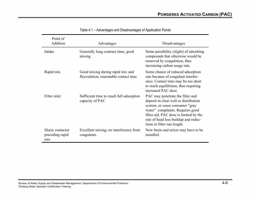
Table 4.1 – Advantages and Disadvantages of Application Points
Point ofAddition Advantages Disadvantages
Intake Generally long contract time; goodmixing
Some possibility (slight) of adsorbingcompounds that otherwise would beremoved by coagulation, thusincreasing carbon usage rate.
Rapid mix Good mixing during rapid mix andflocculation; reasonable contact time
Some chance of reduced adsorptionrate because of coagulant interfer-ence. Contact time may be too shortto reach equilibrium, thus requiringincreased PAC dose.
Filter inlet Sufficient time to reach full adsorptioncapacity of PAC
PAC may penetrate the filter anddeposit in clear well or distributionsystem, or cause consumer "graywater" complaints. Requires goodfilter aid. PAC dose is limited by therate of head loss buildup and reduc-tions in filter run length.
Slurry contactorpreceding rapidmix
Excellent mixing; no interference fromcoagulants
New basin and mixer may have to beinstalled.
POWDERED ACTIVATED CARBON (PAC)
Bureau of Water Supply and Wastewater Management, Department of Environmental Protection 4-7 Drinking Water Operator Certification Training
Dose
Influencing Factors Several factors determine the PAC dose needed. They include:
Concentration of organic contaminant,
The nature of the organic contaminant,
The water temperature,
The contact time available, and
The concentrations of chemicals that interfere with the adsorption process. Common Dosages
PAC doses are usually in the neighborhood of 2-20 mg/L for moderate taste and odor problems.
• To correct PAC dosage a threshold odor number (TON) test can be done.
They can go as high as 100 mg/L during periods of severe taste and odor or a chemical spill. Determining Dosage The required dosage is determined by conducting a Jar Test.
To perform a jar test, various doses of PAC are added to raw water and stirred for a time equal to the contact time in the plant.
Any chemicals that are added while the PAC is still in the water are also added at the appropriate times and doses.
POWDERED ACTIVATED CARBON (PAC)
Bureau of Water Supply and Wastewater Management, Department of Environmental Protection 4-8 Drinking Water Operator Certification Training
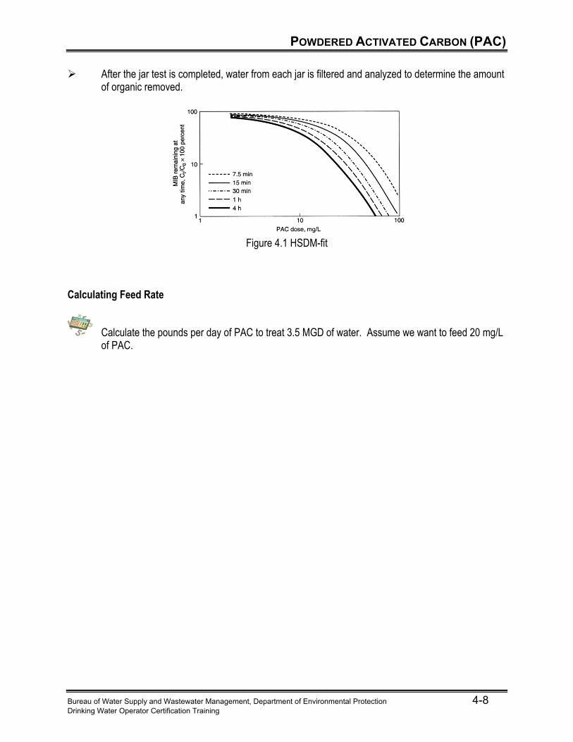
After the jar test is completed, water from each jar is filtered and analyzed to determine the amount of organic removed.
Figure 4.1 HSDM-fit
Calculating Feed Rate
Calculate the pounds per day of PAC to treat 3.5 MGD of water. Assume we want to feed 20 mg/L of PAC.
POWDERED ACTIVATED CARBON (PAC)
Bureau of Water Supply and Wastewater Management, Department of Environmental Protection 4-9 Drinking Water Operator Certification Training
Feed Equipment
Dry System
A dry system is generally better for plants that use PAC infrequently and will have a maximum feed rate less than a few hundred pounds per hour.
A dry feeding system will include:
• A hopper where the PAC is stored. The hopper should include a bag loading system to minimize dust and operator contact with the chemical. The hopper should also include an agitator or vibrator to move the PAC to the bottom of the hopper during feeding.
• A volumetric feeder to meter out the PAC. • A dissolver or mixer tank to mix the PAC with clean water. • An eductor to move the PAC solution to the PAC feed point. • A dust collector to prevent carbon dust from entering the plant. • Depending on the type of shipment, a monorail with trolley and crane may also be needed to
lift large sacks of PAC. A bulk bag unloader and conveyor may also be used. Slurry System
Creating a slurry to add PAC prevents floating and provides more evenly distributed. To feed PAC in the slurry form, clean water is added to the PAC. The slurry must be continuously mixed or the PAC will settle and solidify. Carbon can be added to the slurry tank either by adding bags of carbon or in bulk directly from the delivery truck. Slurry is mixed at a concentration of about 1 lb/gal.
Equipment for feeding PAC in a slurry form includes: • A slurry tank to contain the slurry. • A mixer to keep the PAC in suspension. • A bag loader, to be used if the carbon is delivered in sacks and not transferred directly to the
slurry tank from the truck. • A dust collector to prevent carbon dust from entering the plant. • A tank level transmitter to monitor the amount of carbon slurry in the tank. • A meter for the water supply to measure the amount of water used in creating the slurry, so
that the slurry concentration is correct. • A diaphragm metering pump, eductor, or rotary volumetric feeder for transferring the slurry to
the feed point.
When using PAC in a slurry, the tank, mixer impeller, and piping should be corrosion and erosion resistant.
POWDERED ACTIVATED CARBON (PAC)
Bureau of Water Supply and Wastewater Management, Department of Environmental Protection 4-10 Drinking Water Operator Certification Training
Carbon Contactors
Carbon contactors may be used to increase the available PAC contact time before chemicals are added. The carbon contactor can be in the form of a carbon contact basin or a slurry recirculator. Carbon Contact Basin
The carbon contact basin is just a basin, usually rectangular, provided upstream of other chemical addition to increase the available detention time.
Mixing is provided to keep the carbon in suspension. Baffling can be added to help prevent short-circuiting.
The PAC is removed from the water during subsequent treatment. Slurry Recirculation Tank
Figure 4.2 – Slurry Recirculation Tank
POWDERED ACTIVATED CARBON (PAC)
Bureau of Water Supply and Wastewater Management, Department of Environmental Protection 4-11 Drinking Water Operator Certification Training
How it works:
• The slurry recirculation tank is located upstream of chemical feed points. • The influent is introduced in the center of the basin, where it is mixed with the recirculated
solids. • It then enters an area underneath a hood where secondary mixing occurs and contact time is
achieved. • Then the water passes underneath the edge of the hood into the clarification zone where the
solids settle and the clarified water exits via radial effluent launders. • A recirculation flow from the primary mixing area to the settling area creates a flow where
solids are recirculated to the primary mixing area. • The solids are usually collected with a rake rotating around the center of the unit. The rake
pushes the solids toward a centrally located hopper, where the solids are discharged to waste.
One advantage of the slurry recirculation tank is that the solids have a longer detention time than
the water since they are recirculated. This way, more of the adsorption capacity of the PAC will be used up before the PAC is removed.
Equipment for a slurry recirculation tank includes a conical reaction well, a recirculation drum, the influent pipe, an influent baffle, one drive each for the sludge collection rake and the turbine mixer, the collection rake, and a bridge to the center of the unit.
POWDERED ACTIVATED CARBON (PAC)
Bureau of Water Supply and Wastewater Management, Department of Environmental Protection 4-12 Drinking Water Operator Certification Training
Operation and Monitoring
Monitoring Monitoring for organics needs to be done before, during, and after the operation of the PAC adsorption process. It is through the data collected that the need for PAC use or adjustment to the PAC dose is identified. Recorded historical data is also useful in predicting when PAC may be needed, how much PAC will be used, and how the required PAC dose will change with water quality conditions.
Before PAC System Use • The initial testing is done to see if the identified organics are present. • If they are, and treatment begins, monitoring is continued during the treatment process.
During PAC System Use
• Measure organics before and after contact with the carbon. The PAC dose can be adjusted based on these results.
• Monitor pH, temperature, and concentration of natural organic matter (using TOC, DOC, or other indicators of organic concentration mentioned in Unit 3) as they can affect PAC dose. − pH and temperature will both affect the adsorption rate. − Other organics may compete with the organic of interest, reducing adsorption efficiency.
After PAC System Use
• Once the organics have been removed and there is no longer a need for treatment, the operation ends.
• Continued monitoring for the organics of interest will start the cycle over and serve as the “Before PAC System Use” section mentioned above.
Operation
By collecting data on PAC dose and the resulting removal of the organic under various water conditions, trending charts can be developed that will help predict the correct dose needed to remove a certain amount of contaminant.
While feeding PAC, downstream processes may also have to be adjusted to account for the
increase of suspended solids in the water. In particular, chemical doses may need to be increased. Filter effluent should also be monitored to make sure that PAC isn't passing into the finished water.
When transferring carbon into a slurry tank, the carbon should be added below the surface of the
water to minimize dust.
POWDERED ACTIVATED CARBON (PAC)
Bureau of Water Supply and Wastewater Management, Department of Environmental Protection 4-13 Drinking Water Operator Certification Training
Maintenance
Maintenance involves keeping the feed equipment in good working order and periodic cleaning of the contact basin or slurry recirculation unit, if one is present.
After transfer of PAC slurry, the lines should be thoroughly flushed to prevent clogging and
excessive corrosion in the pipes.
Damp carbon is extremely corrosive, so any material that comes in contact with wet carbon should be corrosion resistant or lined with corrosion resistant materials.
Common Operating Problems Carbon Dust
PAC is a fine powder and the resulting dust can be a problem, especially with a dry feed system. High levels of carbon dust in the air are explosive and lower levels, if inhaled, will irritate the respiratory tract. Therefore a respirator should be worn when adding PAC. The dust will also coat surfaces near the carbon feeding area, causing the area to become filthy.
Use proper ventilation to minimize dust.
Improper Selection of Application Point
If there is not enough detention time before chemical addition, reactions with chlorine or other oxidants or coating with coagulant will significantly reduce the adsorption capacity of the carbon and organics will not be removed effectively.
Select a different feed application point to increase detention time. Another option is to avoid
adding chlorine or oxidants until later in the treatment process, if possible. PAC Pass Through
If PAC passes through the filters, the water will have a black color, causing customer complaints. This is usually caused through inadequate coagulation/flocculation or large amounts of PAC added just before the filter.
Move the feed point or adjust the coagulation/flocculation process.
POWDERED ACTIVATED CARBON (PAC)
Bureau of Water Supply and Wastewater Management, Department of Environmental Protection 4-14 Drinking Water Operator Certification Training
Taste and Odor Problems Activated carbon removes taste and odor by the absorption process. Removing of taste and odor from decaying vegetation by activated carbon is readily used. Factors disturbing the PAC adsorption efficiency will directly affect the taste and odor.
Taste and odor may remain, especially if chlorine is added too close to the PAC application point. Chlorine may react with organics producing compounds that are difficult to adsorb.
• Optimize the PAC efficiency by increasing the dose of PAC, moving the feed point, or
changing the oxidant feed point.
Poor Pre-Treatment Performance
High doses of PAC may make coagulation or flocculation difficult, increasing the solids loading on the filters.
• Decrease the dose of PAC.
Loss of Adsorption Capacity
Carbon will adsorb some gases during storage that can reduce its adsorption efficiency.
• Store bags of carbon in a climate controlled area and rotate the stock.
GRANULAR ACTIVATED CARBON (GAC)
Bureau of Water Supply and Wastewater Management, Department of Environmental Protection 4-15 Drinking Water Operator Certification Training
GAC Properties
Effective Size – the size opening through which 10% of GAC will pass. The effective size of GAC is between 0.6 and 0.9 mm.
Uniformity Coefficient – the ratio of the size opening that will allow 60% of the GAC to pass to the effective size of the GAC. It is an indication of the range of sizes in a GAC sample. In the United States, a uniformity coefficient of about 1.9 is favored because it allows the GAC to re-stratify more easily after backwashing.
Apparent Density – the density of the mass per unit volume of occupied bed space for non-stratified dry carbon. GAC apparent density is in the range of 0.4 to 0.5 g/cm3
Equipment Types GAC adsorption systems can be classified by four characteristics: Driving Force, Flow Direction, Configuration, and Placement. Driving Force - Gravity vs. Pressure
Gravity filters are usually used in medium to large-sized systems, because they become more economical at larger scale. They should be selected if: • Wide variations in flow rate are not needed, such as in a filter/adsorber where the contactor is
also used to remove turbidity. • Large pressure drops are not desirable for operating conditions. • Visual observation of the GAC is needed.
When the driving force is pressure, the GAC is enclosed in a pressure contactor, allowing the
contactor to be operated at a wide range of flow rates. • One advantage of the pressure contactor is that it can be prefabricated and then delivered to
the site. • One disadvantage is that it is difficult to observe the condition of the GAC.
GRANULAR ACTIVATED CARBON (GAC)
Bureau of Water Supply and Wastewater Management, Department of Environmental Protection 4-16 Drinking Water Operator Certification Training
Flow Direction - Downflow vs. Upflow
Downflow contactors are more commonly used in water treatment than upflow contactors.
Upflow contactors can be operated in a packed bed or expanded bed mode. The media will remain packed at lower flow rates and will expand at higher flow rates. • In a pulsed-bed contactor, water is applied upward through the contactor.
− As the carbon at the bottom of the contactor is spent, it is removed and fresh carbon is applied to the top of the contactor.
− In this way, the freshest carbon is always seeing the cleanest water. Configuration - Parallel vs. Series
If parallel contactors are staggered, with the carbon in each contactor at different levels of exhaustion, then one contactor can have effluent contaminant concentrations higher than the treatment goal, but when blended with the effluent from the other contactors, the combined effluent still meets the treatment goal. In this way, the life of the carbon can be extended.
If contactors are in series, when the first contactor is still removing some of the contaminant, but
not as much as is required, the following contactors will remove the rest. The carbon doesn't need to be replaced until the first contactor is no longer adsorbing any of the contaminant. • Because the carbon can be used longer without replacement, carbon use rates decrease. • Once the carbon in the first contactor is replaced with fresh carbon, the flow through the
contactors is adjusted so that the fresh contactor is the last one. In general, it is more effective to operate in series only when removing a high percentage of the contaminant. The complexity of the piping in series operation increases the cost over parallel operations, especially if more than two contactors are needed.
Figure 4.3 – Series System and Parallel System
GRANULAR ACTIVATED CARBON (GAC)
Bureau of Water Supply and Wastewater Management, Department of Environmental Protection 4-17 Drinking Water Operator Certification Training
Placement - Pre-Filtration vs. Filter/Adsorber vs. Post-Filtration The following are some guidelines in selecting a location for the adsorber.
Generally, pre-filtration is not used in water treatment. • The higher turbidity of pre-filtration water increases the need for backwashing. • Higher concentrations of organics and coagulant compete with the target organic for
adsorption sites.
Post-filtration is more commonly seen in water treatment plants because it makes effective use of the adsorption capacity of the GAC. • With most other contaminants removed, the GAC will last longer and the need for GAC
replacement or regeneration is minimized. • If biomass growth is not a problem, the column may be operated without backwashing,
because particles are removed before the contactor.
GAC can be used alone or in conjunction with traditional filter media to act as a combination filter and adsorber. • This placement has the advantage of decreasing space by combining two processes, but it
increases the backwashing frequency compared to a post-filtration GAC bed, which may lead to greater carbon loss.
• Because the water isn't as clean as the post-filtration water, the adsorption capacity of the carbon may be used up faster, requiring more frequent replacement or regeneration.
Equipment Properties Two major properties of a GAC contactor are the empty bed contact time (EBCT) and the hydraulic loading rate.
The empty bed contact time is the volume of the empty GAC bed divided by the volumetric flow rate of the water entering the bed. It is a way of describing the amount of time the water is in contact with the GAC. While the EBCT will be greater than the true contact time because it does not account for the bed volume occupied by the GAC, it is used because it is a simple calculation to make. For most water treatment applications, EBCT usually ranges from 5 to 25 minutes.
The hydraulic loading rate is the volumetric flow rate per cross-sectional area of the GAC
adsorption bed. The effect of the loading rate on adsorption is minimal, but it does affect the pressure drop through the bed. Loading rates range from 0.4 to 12 gpm/ft2, and are most commonly around 3 to 4 gpm/ft2.
GRANULAR ACTIVATED CARBON (GAC)
Bureau of Water Supply and Wastewater Management, Department of Environmental Protection 4-18 Drinking Water Operator Certification Training
Retrofitting Existing Conventional Filters
By replacing all or part of the existing media with GAC, the bed can be operated as a
filter/adsorber. • If the existing filter media was sand only, equipment may have to be modified to reduce
backwash for the GAC. • If anthracite was used, backwash rates for the GAC should be similar.
GAC can be placed directly on top of sand or graded gravel. There are also several types of
underdrains that allow the GAC to be placed directly on top of the underdrain, including wedge wire screen type or block underdrains. Block underdrains will have a permeable membrane placed on top of them to minimize GAC loss through the underdrain and promote even distribution of backwash water.
Many split-cell filters do not have enough bed depth to provide enough contact time. One way to
provide more space is by retrofitting the split-cell to create upflow in one cell and downflow in the other cell. This change will provide the additional bed depth needed.
Figure 4.4 – Retrofitted Split-Cell Filters
GRANULAR ACTIVATED CARBON (GAC)
Bureau of Water Supply and Wastewater Management, Department of Environmental Protection 4-19 Drinking Water Operator Certification Training
Operation and Monitoring
As a new GAC system begins adsorbing the organic, the top layer will adsorb most of it, and there
will be little of the organic left in the water for lower layers to adsorb. Depending on the organic, there may be none left in the water by the time it reaches the bottom layers of the GAC bed.
As the system ages, however, the top layer will become saturated with the organic and will no
longer adsorb any more of it. Then the layer below the top layer will be exposed to higher concentrations of the organic and so will adsorb more of it.
The section of the column where the contaminant is being actively adsorbed; that is the area
between the saturated portion of the column and the area where no more contaminant is in the water; is known as the mass transfer zone. The saturated carbon is called exhausted.
Figure 4.5 – Mass Transfer Zone
As the system continues to age, the mass transfer zone moves downward through the column and
more of the carbon in the column becomes exhausted. Finally, the mass transfer zone reaches the bottom of the column, and there is some of the contaminant remaining in the effluent from the GAC bed.
GRANULAR ACTIVATED CARBON (GAC)
Bureau of Water Supply and Wastewater Management, Department of Environmental Protection 4-20 Drinking Water Operator Certification Training
When the effluent contaminant concentration is greater than the maximum allowable concentration,
this is known as breakthrough. The amount of operating time before breakthrough depends upon both the GAC properties and the design of the bed.
INFLUENTCONCENTRATION
EFFLUENTCONCENTRATION
TIME IN OPERATION
EXHAUSTION
Figure 4.6 – Typical Breakthrough Curve
When a system has two or more contactors in different stages of saturation, the first can reach
breakthrough before the carbon is replaced. However, if only one contactor is used, then the carbon must be replaced before breakthrough is reached. To determine the remaining life of the carbon, samples of the core of the GAC bed should be periodically collected and analyzed for the remaining adsorption capacity.
To remove the carbon from the contactor, it is easiest to form a slurry to transport the GAC from
the contactor. Dilution water can be added through the underdrains or near the bottom of the filter wall. Ports at the bottom of the contactor are used to remove the slurry.
Storage and transfer of carbon to the contactors should be done in a slurry form for large systems.
The slurry should be about 1 to 3 lbs/gal.
The GAC contactor may also have to be periodically backwashed. • If the GAC is being used pre-filtration or in a filter/adsorber, it will have to be backwashed
more frequently than for a post-filter. • A post-filter will usually only have to be backwashed if biological fouling is a problem.
GRANULAR ACTIVATED CARBON (GAC)
Bureau of Water Supply and Wastewater Management, Department of Environmental Protection 4-21 Drinking Water Operator Certification Training
The backwashing rate for a GAC bed depends upon the particle size and apparent density of the
GAC. • When backwashing, care should be taken to ramp the backwash rate up slowly. If the rate is
not ramped, the entire carbon plug may be lifted, rather than expanding the carbon from the top down. Suggested rates are starting at 3-4 gpm/sf and ramping up to 14-15 gpm/sf.
• When ending backwashing, the backwash rate should be ramped back down, to allow the carbon to restratify. If the layers mix, and GAC particles that were near the top of the column and have adsorbed a large amount of the contaminant move down, it is possible that some of the contaminant will desorb as the GAC comes in contact with lower concentrations of the contaminant lower in the column.
Figure 4.7 Proper Backwash Rate
Backwashing should be minimized because the agitation will break down the GAC.
Backwashing can either be done on a scheduled basis, when pressure drop is too high, or when
biological growth becomes too great. If backwashes are too infrequent, it may require longer washes to remove all the built up dirt and biological growth.
GRANULAR ACTIVATED CARBON (GAC)
Bureau of Water Supply and Wastewater Management, Department of Environmental Protection 4-22 Drinking Water Operator Certification Training
Control Tests For GAC contactors, control tests are similar to those used for conventional filters. They include:
The head loss should be monitored to indicate when backwashing is necessary.
The effluent turbidity should be measured, especially for filter/adsorbers or post-filtration contactors. High turbidity is an indication that particles are breaking through the GAC contactor. High turbidity in a post-filtration contactor may be the result of activated carbon powder abraded from the GAC particles or may be the result of biological growth sloughing off of the GAC.
The bed condition should be visually inspected for cracks, brittleness, biological growth,
destratification, or other indications of problems with the media.
Distance between the top of the carbon and the top of the washwater trough should be measured about every 3 months to estimate carbon loss.
Core samples of the carbon bed should be taken about every 6 months for filter/adsorbers or every
3 months for post-filtration contactors to determine remaining bed life.
Organic analyses of the influent and effluent should be conducted to measure treatment effectiveness.
As head loss builds due to particle entrapment or biological growth, the effluent flow will tend to
decrease. The effluent flow should be monitored so adjustments can be made to keep the flow at the desired rate.
In an open contactor, the filter water level should be monitored so the bed does not become dry or
the water does not overflow the contactor.
Maintenance
Steel contactors are usually lined with rubber or epoxy or manufactured from 316 stainless steel. A rubber lining will usually last 10 to 15 years before replacement is needed.
The underdrain should be inspected every time carbon is replaced.
Carbon slurry transfer lines should be thoroughly flushed after each use to prevent plugging and
accelerated corrosion.
For an eductor transfer system, the lifetime of the eductor should be enough to transfer approximately 2 to 4 million pounds of carbon before replacement is required.
GRANULAR ACTIVATED CARBON (GAC)
Bureau of Water Supply and Wastewater Management, Department of Environmental Protection 4-23 Drinking Water Operator Certification Training
Carbon Regeneration
GAC can be disposed of when it is expired or can be regenerated. Disposal is usually most cost effective for small systems using less than 500 lb/day. Off-site regeneration is economical for systems using 500 to 1500 lb/day. On-site regeneration is only cost-effective for systems using large amounts of carbon, greater than 2000 lb/day. Most US systems fall in the range of 500 to 1500 lb/day.
Off-site disposal • Spent carbon is usually sent to a landfill or incineration facility. If large amounts of toxic
materials have been adsorbed, disposal may be difficult (this usually is not a problem for water treatment applications).
• Another option is to trade the carbon back in to the manufacturer for new carbon. The manufacturer could regenerate the carbon and sell it for non-drinking water applications.
Off-site for regeneration
• Care must be taken that only the carbon from the water treatment plant is returned to the plant, along with virgin carbon as the make-up carbon for carbon lost during regeneration.
• Receiving regenerated carbon from municipal or industrial waste treatment must be avoided because the possibility, although unlikely, exists for desorption of any remaining toxic compounds into the water.
Regeneration can be done using one of three methods—steam, chemical, or thermal. Steam and
chemical regeneration are usually only used for industrial waste treatment where the adsorbate is recovered.
The following steps are followed for thermal regeneration:
1. Dewatering to 40 to 50% moisture content by draining. 2. Drying at temperatures up to 200ºC. 3. Baking or pyrolosis of adsorbates at 500 to 700ºC. 4. Activating carbon at temperatures above 700ºC. 5. Quenching regenerated carbon.
GRANULAR ACTIVATED CARBON (GAC)
Bureau of Water Supply and Wastewater Management, Department of Environmental Protection 4-24 Drinking Water Operator Certification Training
Furnace Types Commonly Used for Regeneration
Electric Infrared Oven - The carbon is placed on a metal conveyor belt, transported through various insulated chambers or zones, and heated by electric infrared elements with increasingly higher temperatures. After activation, the carbon is discharged into a quenching tank.
Fluidized Bed Furnace - Carbon particles are suspended by an upward-flowing gas stream. Steam
is injected to control the temperature. The wet carbon is dried in an upper zone then moves by gravity down to a lower section for incineration. In between the two zones, air is injected to burn off organics, carbon monoxide, and hydrogen released during regeneration in the lower zone. The heat produced is used to dry the carbon above and to heat the gas suspending the carbon.
Multiple-Hearth Furnace - The carbon begins at the top of a series of hearths. A rotating center
shaft with arms and rabble blades is used to slowly move the carbon in a spiral path toward the edge of the hearth, alternating inwards and outwards. It drops from hearth to hearth, until it reaches the bottom and is quenched. Burners are located at the bottom of the furnace and can also be located at higher hearths for better control. Steam is usually added in the lower part for temperature control.
Rotary Kiln - Carbon is moved through a long cylindrical tube that is at a slight incline to the
horizontal. The cylinder is rotated, moving the carbon through the tube.
(c) Cross section of multihearth furnance (d) Cross section of rotary kiln furnace
(a) Cross section of infrared tunnel furnace (b) Cross section of two-stage fluidized bed furnace
(c) Cross section of multihearth furnance (d) Cross section of rotary kiln furnace
(a) Cross section of infrared tunnel furnace (b) Cross section of two-stage fluidized bed furnace
Figure 4.8 – Furnace Types Used for Regeneration
GRANULAR ACTIVATED CARBON (GAC)
Bureau of Water Supply and Wastewater Management, Department of Environmental Protection 4-25 Drinking Water Operator Certification Training
Operating Problems
Bacterial Growth A GAC bed makes a good habitat for bacteria, with the adsorbed organics a ready supply of food. As a result, the bacterial counts of the effluent may be thousands of times higher than those in the influent. While these bacteria can enhance organic removal, bacteria in the distribution system should be avoided. The bacterial counts in the finished water should be monitored and chlorination controlled accordingly. Some plants use chlorinated backwash. Chlorine in the influent is not recommended because it will increase the concentration of halogenated organics and will make the carbon more brittle.
Anaerobic Conditions - Biological activity in the contactor can lead to anaerobic portions of the contactor, leading to odor problems. Anaerobic conditions are likely to occur if there are high concentrations of ammonia in the influent, the dissolved oxygen concentration is low in the influent, or if the bed is not operated for lengthy periods of time. Perform routine chlorinated backwash. Another option is to increase oxygen—aerate.
Changing Bed Depth During the day to day operation, the depth of the carbon bed will change. After backwashing, the carbon may expand about 8% and during filtration, it may recompress 5 to 15%. When new carbon is added, the natural expansion of the carbon should be taken into account so the bed is not overfilled once the carbon expands. Desorption of Adsorbed Organics Desorption may occur for several reasons.
If the bed is destratified during backwashing, GAC that has adsorbed large amounts of the organic may be moved lower in the column and be exposed to lower concentrations of the organic, resulting in desorption.
If concentrations of the organic in the influent fluctuate, a period of high concentration of the
organic followed by a period of low concentration of the organic could have similar results.
The water temperature and pH also affect the adsorption equilibrium and if they become less favorable for adsorption and the GAC is near saturation, some desorption could occur.
This effect could be prevented by careful backwashing and by not running a contactor too close to exhaustion. This way, if organics desorb from upper layers of the contactor, the lower layers will still have capacity to adsorb the organic that is released by the upper layers.
GRANULAR ACTIVATED CARBON (GAC)
Bureau of Water Supply and Wastewater Management, Department of Environmental Protection 4-26 Drinking Water Operator Certification Training
Backwashing and Loss of Carbon Carbon is normally lost through backwashing and abrasion. During normal operation, approximately 0.2 to 1 inch per year of loss is typical. More than this is generally caused either by poor backwashing procedures or an underdrain failure. Manufacturer's recommendations for backwashing based on particle size and water temperature should be followed.
Biological GAC (BAC)
As an alternative method of utilizing a GAC contactor, bacterial growth on the GAC is sometimes promoted. This method of operation is known as biological GAC (BAC). A coating of biomass on the GAC, known as a biofilm, is used to remove the organics through biodegradation—many organic contaminants are readily used by bacteria and other microorganisms for food. These compounds are known as assimilable organic carbon (AOC). • Ozonation or treatment with hydrogen peroxide will increase the amount of AOC in the water.
In these cases, it is only necessary to replace the GAC lost through normal operation of the
contactor, since the GAC is used as a substrate for growth rather than for adsorption.
Periodic backwashing to remove excessive growth is required. A low level of chlorine in the influent may be able to minimize growth so backwashing is required less frequently. However, the chlorine may cause brittleness in the carbon and may react with some of the organics to form halogenated organics, so chlorine use should be minimal.
Operation, maintenance, and monitoring requirements for a BAC are similar to those for a regular
GAC contactor. • Turbidity measurements are particularly important because bacterial growth is being
encouraged in the column and if a large amount of bacteria is sloughed off the GAC, it could be potentially harmful. For this reason, disinfectant dosing in the finished water is also important.
• An adsorption capacity test does not need to be performed since BAC uses biodegradation rather than adsorption.
SAFETY
Bureau of Water Supply and Wastewater Management, Department of Environmental Protection 4-27 Drinking Water Operator Certification Training
PAC and GAC stored in bags should be kept in a clean dry place on top of pallets so air can
circulate underneath. Space between the stacks should be adequate for walking and access to the carbon. Stacks should be no higher than 6 ft.
Activated carbon will burn so certain safety precautions should be taken.
• Activated carbon dust is especially flammable. The storage area should be fireproof with fire doors separating the area from other areas. Storage bins should be fireproof and equipped for fire control. Dust control equipment and ventilation should be used to minimize the likelihood of fire.
• Carbon should not be stored with gasoline, mineral oils, vegetable oils, or similar materials. When mixed with carbon, they will slowly oxidize until they reach their ignition temperature and ignite.
• Carbon should not be stored with strong oxidizers such as chlorine or potassium permanganate, as spontaneous combustion can result.
• Explosion-proof wiring and equipment should be used in carbon storage and feed areas. • Explosion proof motors are required in a PAC Feed system. • Effective ventilation is important and will help prevent explosions • The Emergency Response Plan for the facility must include contingencies for explosions from
system.
Carbon storage and feed equipment should be enclosed in a separate room so dust will not spread throughout the plant.
Wetted carbon, such as in carbon slurries, will remove oxygen from the air. Enclosed spaces with
carbon slurry may have very low oxygen levels, so care must be taken in entering these areas. Oxygen detectors should be used before entering the enclosed space and anyone entering the area should have a line attached to themselves and another person nearby so they can be removed from the area if problems arise.
Dust masks, face shields, gauntlets, and aprons should be worn when handling carbon bags or
bulk carbon.
UNIT 4 EXERCISE
Bureau of Water Supply and Wastewater Management, Department of Environmental Protection 4-28 Drinking Water Operator Certification Training
UNIT 4 EXERCISE: 20 minutes Fill in the Blank 1. Adsorption is the process of _________________ a substance located in a gas or liquid at the
surface of a solid. 2. Activate carbon removes ___________________________ and ____________________
through the absorption process 3. Four considerations for the placement of an application point for Powered Activated Carbon are:
Adequate contact time between the PAC and the ____________, Coagulant will coat the surface of the PAC and __________ its ability to adsorb the contaminants, PAC will react with ______________, potassium permanganate, and other oxidants and PAC is small enough to pass through a _______________ filter.
True (T) or False (F) 4.____ The slurry system of PAC feed equipment will distribute better and prevent material from floating. 5. ____ A PAC uses much smaller carbon particles than a GAC. 6. ____ A fire may start when activated carbon reacts with oxidizing agents 7 . ____ An operator doesn’t need to wear air protection around activated carbon that has been wetted
down.
UNIT 4 EXERCISE
Bureau of Water Supply and Wastewater Management, Department of Environmental Protection 4-29 Drinking Water Operator Certification Training
8. ____ There are four common operating problems that can occur with the adsorption process. 9. ___ On a regular basis a number of operation control tests can be used in the adsorption process.
Core samples and effluent turbidities are done every 6-months or twice a year.
10. ____ Activated carbon will burn so the following safety precautions should be taken: • Storage area and storage bins should be fireproof. • Dust control equipment and ventilation should be used to minimize dust. • Carbon should not be stored with gasoline, mineral oils, vegetable oils, or similar materials. • Carbon should not be stored with strong oxidizers. • Explosion-proof wiring and equipment should be used in carbon storage and feed areas.
UNIT 4 RESOURCES
Bureau of Water Supply and Wastewater Management, Department of Environmental Protection 4-30 Drinking Water Operator Certification Training
Additional Resources
Water Treatment Plant Design (3rd ed.), (New York: McGraw-Hill, 1998).