Page 1
1
VISUAL PHYSICS ONLINE
MODULE 4.1
ELECTRICITY
ELECTRIC FIELD
Electric field E
Vector
Direction same as the force that would
be exerted on a positive charge
Magnitude E E
Components [2D]
ˆ ˆx yE E i E j
S.I. units
N.C-1 (newton / coulomb)
V.m-1 (volt / metre)
F q E
Page 2
2
Before proceeding with the notes on electric fields, review the topic
on scalar and vector fields and watch the video on electric fields
Review scalar and vector fields
Watch video
As you watch the video, make a summary of the key point.
A scalar field is a region of space where some physical quantity has a
definite value at every point.
A vector field is a region of space where the vector quantity is
specified by its magnitude and direction at every point.
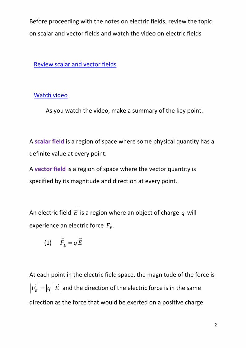
An electric field E is a region where an object of charge q will
experience an electric force EF .
(1) EF q E
At each point in the electric field space, the magnitude of the force is
EF q E and the direction of the electric force is in the same
direction as the force that would be exerted on a positive charge
Page 3
3
placed at that point. Equation (1) is only valid if the charge q does
not change the electric field.
Fig. 1. The direction of the electric field is in the direction of
the force that would act upon a positive charge. EF is the
electric force acting on the charge q at the location where
the electric field is E .
Page 4
4
How are electric fields produced?
We know that electric charges exert attractive or repulsive forces on
other charges. So, any charge distribution gives rise to an electric
field. Another way in which electric fields are generated is due to the
fact that a changing magnetic field induces a changing electric field.
The reverse is also true, a changing electric field induces a changing
magnetic field. This is how electromagnetic waves propagate
through space: a changing magnetic field induces a changing electric
field which generates a changing magnetic field, and so on and on. An
electromagnetic wave is self-propagating.
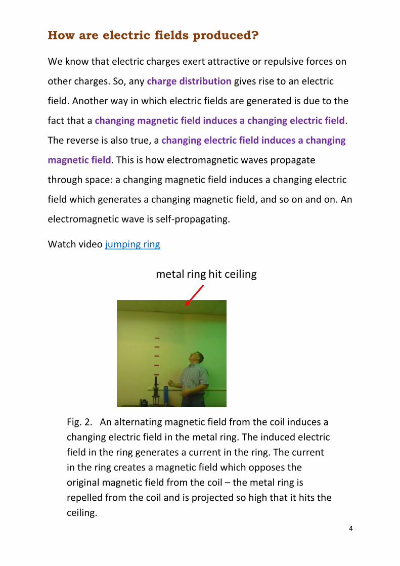
Watch video jumping ring
Fig. 2. An alternating magnetic field from the coil induces a
changing electric field in the metal ring. The induced electric
field in the ring generates a current in the ring. The current
in the ring creates a magnetic field which opposes the
original magnetic field from the coil – the metal ring is
repelled from the coil and is projected so high that it hits the
ceiling.
Page 5
5
The magnitude of the electric field E E around a single point-
like charge Q is given by
(2) 2
1
4
QE E
r inverse square law
When an object of charge q is placed within this field E , it will
experience an electric force F described by Coulomb’s Law
(3) 2
1
4
q QF F
r
F q E
Coulomb’s Law
The concept of electric field is much more powerful than the concept
associated with electrical force. The physical quantity electric field is
used extensively in describing electromagnetic phenomena, whereas
force is barely used. The concept of electric field is useful in
visualizing electrical interactions taking place via an electric field.
Consider two charge objects A and B that are initially a fixed distance
apart. Suddenly the charged object B is moved away from A so the
separation distance increases. The charged object A does not feel a
different force or different electric field instantaneously. Rather, at
the location of the charged object A, the force on A and the electric
field at this point does not change in the time required for light to
travel from B to A. So, disturbances in the electric field arising from
accelerated charges are propagated at the finite speed of light.
Page 6
6
This is no mere accident. Light consists of electric and magnetic fields
travelling through space. An electric field become detached from the
electric charge generating it. Such electric and magnetic fields
(electromagnetic waves) are physically real in the sense that one can
attribute to them such “mechanical” properties as energy and
momentum.
Fig. 3. Self-propagating electromagnetic wave.
Page 7
7
Electric field lines (electric lines of force)
One may use a number of vectors to represent an electric field. The
vectors all point radially outward for a positive point-like charge
(radially inward for a negative charge) and their magnitude (length) is
chosen to be inversely proportional to the square of the distance
from the charge.
Fig. 4. The electric field of a point-charge represented by E
vectors.
However, this is not the best way to visually represent an electric
field since the length of the arrows are generally too small to view
when the electric field has a small value. We can map an electric field
by using electric field lines. The direction of the lines gives the electric
field direction and the number of field lines per unit area (density of
electric field lines) gives the magnitude of the electric field. The
tangent to an electric field line at any point gives the direction of the
electric force on a positive charge. The electric field lines are a very
useful means of visualizing the electric field. The electric field is a real
Page 8
8
physical quantity that can be measured, however, the lines which
represent the field are a useful fiction.
Electric field lines originate from positive charges and terminate on
negative charges.
When the field lines are crowded together the field is strong.
Where the lines are uniformly (equally) spaced and parallel, the field
is uniform (constant).
Any object carrying a single charge (either positive or negative), when
viewed from a great distance will have an electric field of a point-like
charge where 21 /E r .
The field lines do not show the trajectories of a charged particle
released in an electric field. However, knowing the electric field, one
finds the force acting on the object from which one can compute the
particle’s acceleration, then velocity, then displacement at all times
given the initial velocity of the charged particle.
Page 9
9
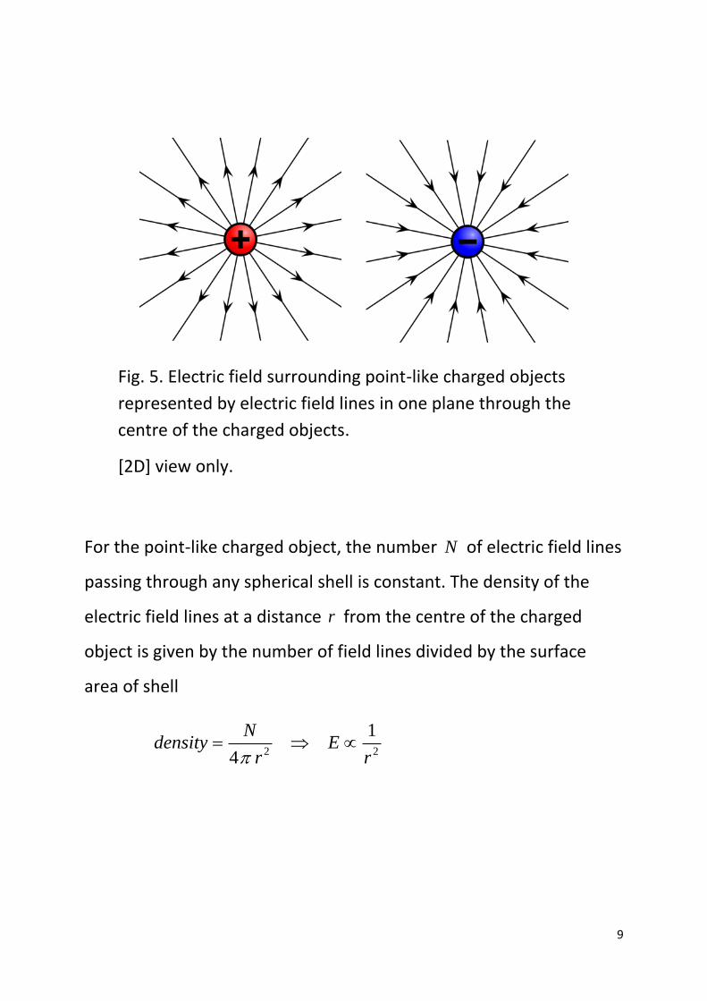
Fig. 5. Electric field surrounding point-like charged objects
represented by electric field lines in one plane through the
centre of the charged objects.
[2D] view only.
For the point-like charged object, the number N of electric field lines
passing through any spherical shell is constant. The density of the
electric field lines at a distance r from the centre of the charged
object is given by the number of field lines divided by the surface
area of shell
2 2
1
4
Ndensity E
r r
Page 10
10
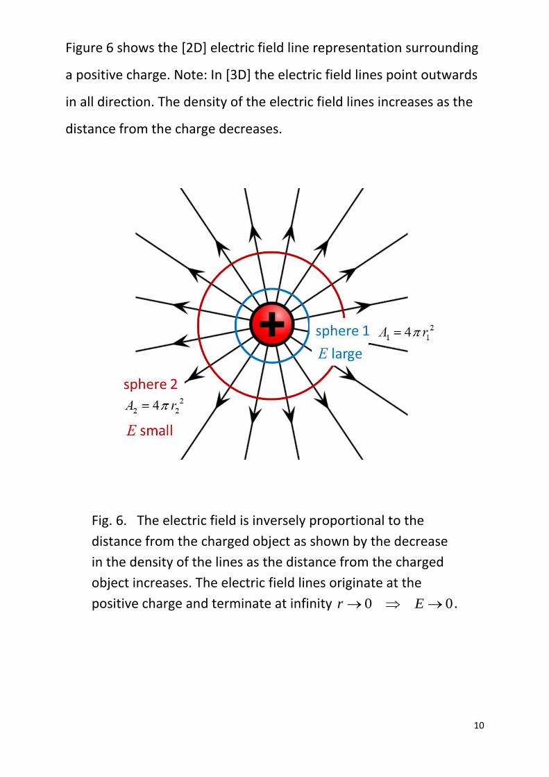
Figure 6 shows the [2D] electric field line representation surrounding
a positive charge. Note: In [3D] the electric field lines point outwards
in all direction. The density of the electric field lines increases as the
distance from the charge decreases.
Fig. 6. The electric field is inversely proportional to the
distance from the charged object as shown by the decrease
in the density of the lines as the distance from the charged
object increases. The electric field lines originate at the
positive charge and terminate at infinity 0 0r E .
Page 11
11
The number of field lines drawn from a charged object is
proportional to the magnitude of the charge.
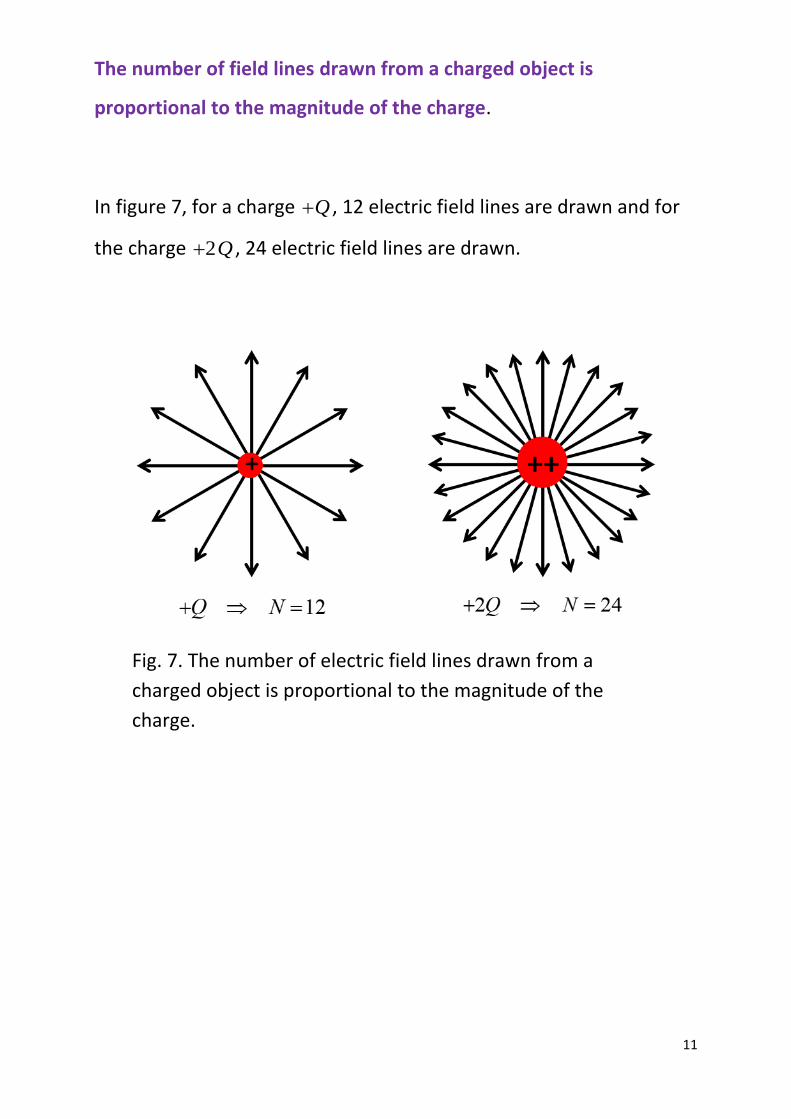
In figure 7, for a charge Q , 12 electric field lines are drawn and for
the charge 2Q , 24 electric field lines are drawn.
Fig. 7. The number of electric field lines drawn from a
charged object is proportional to the magnitude of the
charge.
Page 12
12
The electric field of an electric dipole is shown in figure 8. An electric
dipole is composed of the two charges of equal magnitude but
opposite sign separated by a fixed distance. The electric field lines
originate from the positive charge and terminate on the negative
charge.
Fig.8. Electric field surrounding an electric dipole. The
electric field lines originate from the positive charge and
terminate at the negative charge.
Page 13
13
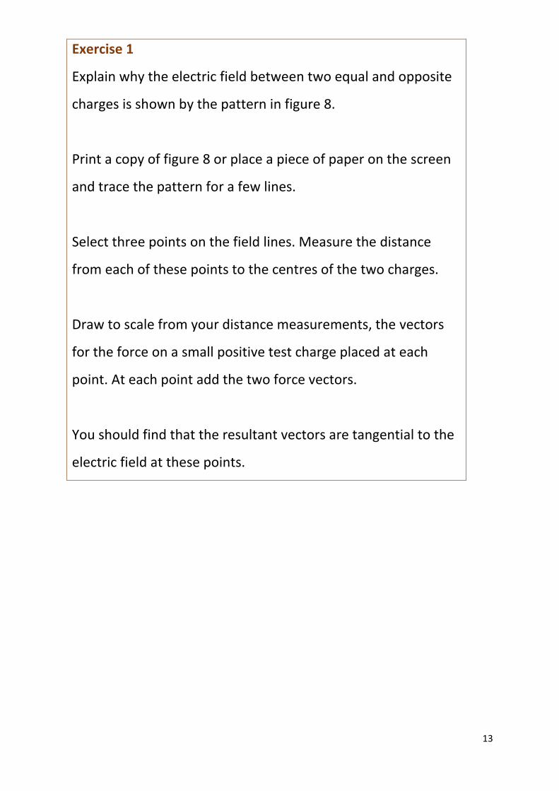
Exercise 1
Explain why the electric field between two equal and opposite
charges is shown by the pattern in figure 8.
Print a copy of figure 8 or place a piece of paper on the screen
and trace the pattern for a few lines.
Select three points on the field lines. Measure the distance
from each of these points to the centres of the two charges.
Draw to scale from your distance measurements, the vectors
for the force on a small positive test charge placed at each
point. At each point add the two force vectors.
You should find that the resultant vectors are tangential to the
electric field at these points.
Page 14
14
Figure 9 shows the electric field pattern for the configuration of two
equal positive charged objects separated by a fixed distance.
Fig. 9. Electric field pattern for two equal positively charged
objects. Note: 24 electric field lines originate from each
charge.
Page 15
15
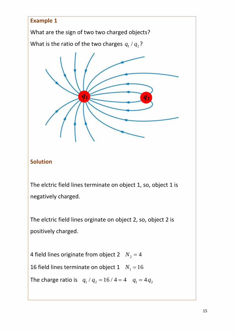
Example 1
What are the sign of two two charged objects?
What is the ratio of the two charges 1 2/q q ?
Solution
The elctric field lines terminate on object 1, so, object 1 is
negatively charged.
The elctric field lines orginate on object 2, so, object 2 is
positively charged.
4 field lines originate from object 2 2 4N
16 field lines terminate on object 1 1 16N
The charge ratio is 1 2 1 2/ 16 / 4 4 4q q q q
Page 16
16
Uniform electric field
A good approximation to a uniform (constant) electric field is the
electric field between two parallel oppositely charged conducting
plates known as a parallel plate capacitor (figure 10). A capacitor is a
passive two-terminal electrical component that stores electrical
energy in an electric field. Capacitors are found in most electronic
circuits. Your mobile phone only functions because of the capacitors
used in the electronic circuits.
Fig. 10. Uniform electric field: two parallel, uniformly
charged plates of opposite sign.
Page 17
17
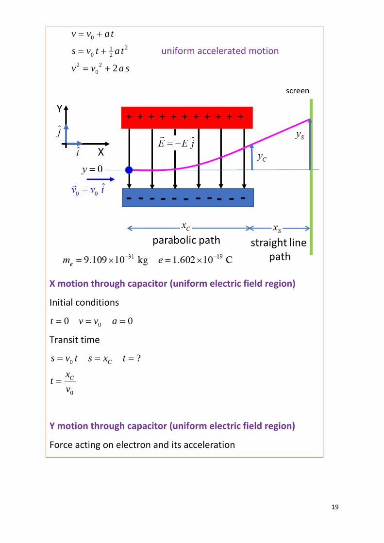
Example 2
A beam of electrons moving in the +X direction with an initial
veloicty 0v enters a region of uniform elctric field E directed in
the +Y direction generated by a pair of oppositely charged
parallel plates (parallel plate capacitor) which has a length Cx in
the X direction.
Determine the path of the electron when it is moving through
the uniform electric field. What is the vertical distance Cy the
electron will be deflected when passing through the uniform
electric field.
Descibe the path of the elctron beam after leaving the uniform
electric field. The electron beam hits a screen located at a
distance Sx from the end of the parallel plate capacitor. What is
the vertical deflection Sy of the electron beam from its original
trajectory when it strikes the screen?
Page 18
18
Solution
Watch Video (concentrate on the motion of charged particles
through a uniform electric field).
Review motion with a uniform acceleration
Review [2D] motion in a plane
Think about how to approach the problem by visulaizing the
physical situation.
Draw an annoated scientifc diagram.
State the known and unknown physical quantities.
State the equations that you will need.
State the physical principles and concepts needed to solve the
problem.
This is a long (difficult ???) problem, but if think about breaking
the problem into four smaller problems, then you will find that
it is not such a difficult problem.
The problem can be solved using the equations for uniform
accelerated motion resolved into the X direction and the Y
direction.
Page 19
19
0
210 2
2 2
0 2
v v a t
s v t a t
v v a s
uniform accelerated motion
X motion through capacitor (uniform electric field region)
Initial conditions
00 0t v v a
Transit time
0
0
?C
C
s v t s x t
xt
v
Y motion through capacitor (uniform electric field region)
Force acting on electron and its acceleration
Page 20
20
E e
e
F e E m a
e Ea
m
Initial conditions
0 0e
e Et v a
m
Time at which electron leaves electric field region
0
Cxt
v
Vertical velocity of electron leaving electric field
0
0 0
C C
e e
x e E xe Ev v at v
m v m v
Vertical displacement of electron leaving electric field
2
21 10 2 2
0
2
2
02
CC
e
CC
e
xe Es v t a t y
m v
e E xy
m v
X motion field free region
Initial conditions
00 0t v v a
Time for electron to travel from capacitor to screen
0
0
?S
S
s v t s x t
xt
v
Page 21
21
Y motion field free region
Initial conditions
0
0
0 0Ce E xt v v a
mv
Vertical displacment for position of electron striking screen
2
2
0 00
2
2
0 00
2
2
0
2
2
2
2
S C
C C SC
e
C C SS
ee
C C S
S
e
y y v t
e E x e E x xy v t
mv vm v
e E x e E x xy
m v vm v
e E x x xy
m v
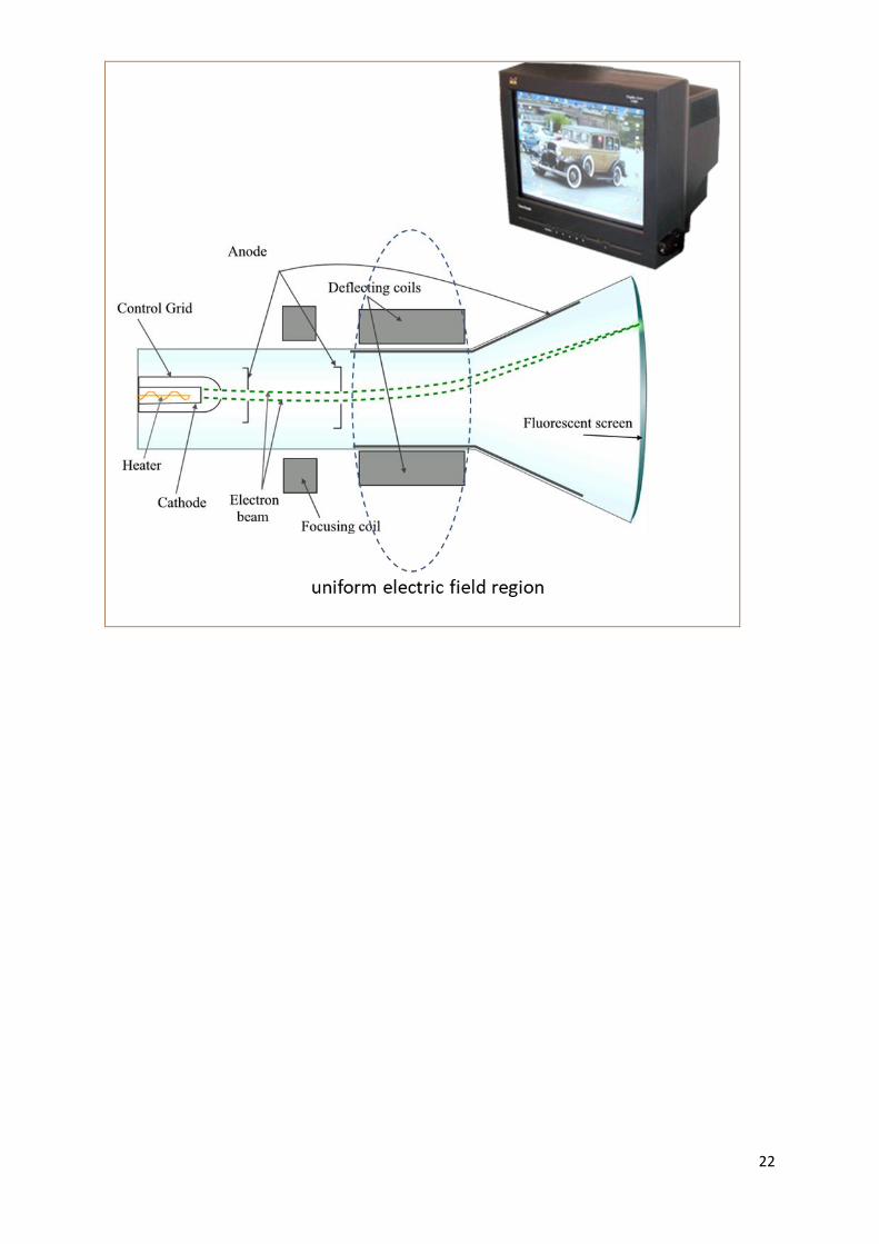
The vertical deflection Sy of the electron on the screen is
proportional to the electric field strength between the plates. In
cathode ray tubes used in television sets of the past, the path of
the electrons through the tube to the screen could be
controlled by changing the electric field between the plates of
the capacitors.
Page 23
23
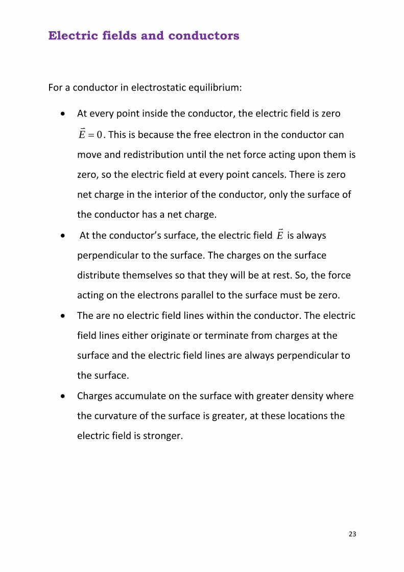
Electric fields and conductors
For a conductor in electrostatic equilibrium:
• At every point inside the conductor, the electric field is zero
0E . This is because the free electron in the conductor can
move and redistribution until the net force acting upon them is
zero, so the electric field at every point cancels. There is zero
net charge in the interior of the conductor, only the surface of
the conductor has a net charge.
• At the conductor’s surface, the electric field E is always
perpendicular to the surface. The charges on the surface
distribute themselves so that they will be at rest. So, the force
acting on the electrons parallel to the surface must be zero.
• The are no electric field lines within the conductor. The electric
field lines either originate or terminate from charges at the
surface and the electric field lines are always perpendicular to
the surface.
• Charges accumulate on the surface with greater density where
the curvature of the surface is greater, at these locations the
electric field is stronger.
Page 24
24
Fig. 11. Positvely charged conductor.
Fig. 12. A neutal conductor in an external electric field.
Page 25
25
Memory Mindmap Summary On one A4 sheet of paper, make a Mindmap of these notes on
electric fields. You can condense these many pages to just one
page containing the essential physics that you must commit to
memory.
VISUAL PHYSICS ONLINE
If you have any feedback, comments, suggestions or corrections
please email Ian Cooper
[email protected]
Ian Cooper School of Physics University of Sydney
http://www.physics.usyd.edu.au/teach_res/hsp/sp/spHome.htm