Elements of Civil Engineering and Engineering Mechanics Elements of Civil Engineering and Engineering Mechanics Dept. of Civil Engg. DSCE Page 1 MODULE 5 KINEMATICS INTRODUCTION TO DYNAMICS Dynamics is the branch of science which deals with the study of behaviour of body or particle in the state of motion under the action of force system. The first significant contribution to dynamics was made by Galileo in 1564. Later, Newton formulated the fundamental laws of motion. Dynamics branches into two streams called kinematics and kinetics. Kinematics is the study of relationship between displacement, velocity, acceleration and time of the given motion without considering the forces that causes the motion, or Kinematics is the branch of dynamics which deals with the study of properties of motion of the body or particle under the system of forces without considering the effect of forces. Kinetics is the study of the relationships between the forces acting on the body, the mass of the body and the motion of body, or Kinetics is the branch of dynamics which deals with the study of properties of motion of the body or particle in such way that the forces which cause the motion of body are mainly taken into consideration. TECHNICAL TERMS RELATED TO MOTION Motion: A body is said to be in motion if it is changing its position with respect to a reference point. Path: It is the imaginary line connecting the position of a body or particle that has been occupied at different instances over a period of time. This path traced by a body or particle can be a straight line/liner or curvilinear. Displacement and Distance Travelled Displacement is a vector quantity, measure of the interval between two locations or two points, measured along the shortest path connecting them. Displacement can be positive or negative. Distance is a scalar quantity, measure of the interval between two locations measured along the actual path connecting them. Distance is an absolute quantity and always positive. A particle in a rectilinear motion occupies a certain position on the straight line. To define this position P of the particle we have to choose some convenient reference point O called origin (Figure 5.1). The distance x 1 of the particle from the origin is called displacement. Let, Figure 5.1
Transcript
Elements of Civil Engineering and Engineering Mechanics Elements of Civil Engineering and Engineering Mechanics
Dept. of Civil Engg. DSCE Page 1
MODULE 5
KINEMATICS
INTRODUCTION TO DYNAMICS
Dynamics is the branch of science which deals with the study of behaviour of body or particle
in the state of motion under the action of force system. The first significant contribution to
dynamics was made by Galileo in 1564. Later, Newton formulated the fundamental laws of
motion. Dynamics branches into two streams called kinematics and kinetics.
Kinematics is the study of relationship between displacement, velocity, acceleration and time
of the given motion without considering the forces that causes the motion, or Kinematics is
the branch of dynamics which deals with the study of properties of motion of the body or
particle under the system of forces without considering the effect of forces.
Kinetics is the study of the relationships between the forces acting on the body, the mass of
the body and the motion of body, or Kinetics is the branch of dynamics which deals with the
study of properties of motion of the body or particle in such way that the forces which cause
the motion of body are mainly taken into consideration.
TECHNICAL TERMS RELATED TO MOTION
Motion: A body is said to be in motion if it is changing its position with respect to a reference
point.
Path: It is the imaginary line connecting the position of a body or particle that has been
occupied at different instances over a period of time. This path traced by a body or particle
can be a straight line/liner or curvilinear.
Displacement and Distance Travelled
Displacement is a vector quantity, measure of the interval between two locations or two
points, measured along the shortest path connecting them. Displacement can be positive or
negative. Distance is a scalar quantity, measure of the interval between two locations measured along the actual path connecting them. Distance is an absolute quantity and always positive. A particle in a rectilinear motion occupies a certain position on the straight line. To define this position P of the particle we have to choose some convenient reference point O called origin
(Figure 5.1). The distance x1 of the particle from the origin is called displacement.
Let, Figure 5.1
Elements of Civil Engineering and Engineering Mechanics Elements of Civil Engineering and Engineering Mechanics
Dept. of Civil Engg. DSCE Page 2
P —> Position of the particle at any time t1 x1—> Displacement of particle measured in +ve direction of O x2—> Displacement of particle measured in -ve direction of O
In this case the total distance travelled by a particle from point O to P to P1 and back to O is not equal to displacement.
Total distance travelled = x1+ xl + x2 + x2 = 2(x1 + x2). Whereas the net displacement is zero.
Velocity: Rate of change of displacement with respect to time is called velocity denoted by v.
Mathematically v = dx/dt
Average velocity: When an object undergoes change in velocities at different instances, the average velocity is given by the sum of the velocities at different instances divided by the
number of instances. That is, if an object has different velocities v1, v2, v3, ... , vn, at times t =
t1, t2, t3, ..., tn, then the average velocity is given by
V = (v1+v2+v3+….vn)/n
Instantaneous velocity: It is the velocity of moving particle at a certain instant of time. To
calculate the instantaneous velocity Δx is considered as very small.
Instantaneous velocity v = Δt0 Δx/Δt
, Speed: Rate of change of distance travelled by the particle with respect to time is called speed. Acceleration: Rate of change of velocity with respect to time is called acceleration
Mathematically a = dv/dt
Average Acceleration
Consider a particle P situated at a distances of x from O at any instant of time t having a velocity v. Let Pl be the new position of particle at a distance of (x + Δx) from origin with a
velocity of (v + Δv). See Figure 5.2.
Elements of Civil Engineering and Engineering Mechanics Elements of Civil Engineering and Engineering Mechanics
Dept. of Civil Engg. DSCE Page 3
Figure 5.2
Average acceleration over a time t, is given by aavg = Δv/Δt
Acceleration due to gravity: Each and everybody is attracted towards the centre of the earth by a gravitational force and the acceleration with which the body is pulled towards the centre
of the earth due to gravity is denoted by 'g'. The value of g is normally taken as 9.81 m/s2.
Newton's Laws of Motion
Newton's first law: This law states that 'everybody continues in its state of rest or of uniform
motion, so long as it is under the influence of a balanced force system'.
Newton's second law: This law states that 'the rate of change momentum of a body is directly proportional to the impressed force and it takes place in the direction of force acting on it.
Newton's third law: This law states that 'action and reaction are equal in magnitude but
Graphical representation: The problems in dynamics can be analysed both analytically and
graphically without compromising on the accuracy. Most of the times graphical
representations can lead to simpler solutions to complicated problems. Using the simple terms
defined in the initial portions of the section, we can draw different types of graphs.
Displacement-time graph: The representation with graph in Figure 5.3 shows that the
displacement is uniform with time. Hence it is understood that the body is under rest as the
displacement is constant with respect to time. The representation with graph in Figure 5.4 shows that the plot is having a constant slope and the variation of displacement is uniform with time. The slope indicates the ratio. of
displacement to time which is equal to velocity of the body; Hence it is understood that the
body is moving under uniform velocity.
Figure 5.5 shows variation of displacement with time as a curve. The tangent to this curve at
any point indicates the velocity of the body at that instant. As can be seen the slope of the
tangent is changing with respect to time and ever increasing, it indicates that the velocity is
changing with respect to time and also indicates that the velocity is increasing with respect to
time. This increasing velocity with respect to time is termed acceleration.
Elements of Civil Engineering and Engineering Mechanics Elements of Civil Engineering and Engineering Mechanics
Dept. of Civil Engg. DSCE Page 4
Figure 5.3 Variation of displacement with time.
Figure 5.4 Variation of displacement with time
Figure 5.5 Variation of displacement with time.
In case of Figure 5.6, the curvature is decreasing, and the slope of the tangent is decreasing
with respect to time and rate change of velocity is decreasing. This is termed as deceleration.
Elements of Civil Engineering and Engineering Mechanics Elements of Civil Engineering and Engineering Mechanics
Dept. of Civil Engg. DSCE Page 5
Figure 5.6 Variation of displacement with time.
Velocity-time graph: A plot of velocity with respect to time is termed as velocity-time graph
Figure 5.7 Variation of velocity with time.
Unit of velocity = v = LT-l
Unit of time = T
Velocity x Time = LT-l
xT=L Distance
Hence, the area under V-T graph will produce the distance traveled by the body/particle
from time t1 to t2, s = v* (t2 –t1,) = vt . . (i)
This is applicable only when the velocity is uniform.
In case of Figure 5.8, the velocity is varying uniformly with respect to time as seen from sloped straight line.
Elements of Civil Engineering and Engineering Mechanics Elements of Civil Engineering and Engineering Mechanics
Dept. of Civil Engg. DSCE Page 6
Figure 5.8 Variation of velocity with time.
The slope of the line is gives acceleration
a = (v2-v1)/(t2-t1) (v2-v1) = a(t2-t1) v2 = v1+a(t2-t1)
= u + at (1) where v = final velocity, u = initial velocity and t = (t2-t1)
As seen from earlier graph, the total distance traveled is given by the area under the curve and
hence the area is given as
S = v1*t + 0.5(v2-v1)t
But acceleration = a = (v2-v1)/t
Substituting, we get
S = v1 x t + 0.5 x at2
or ut + 0.5at2
where u is the initial velocity or velocity at time t1
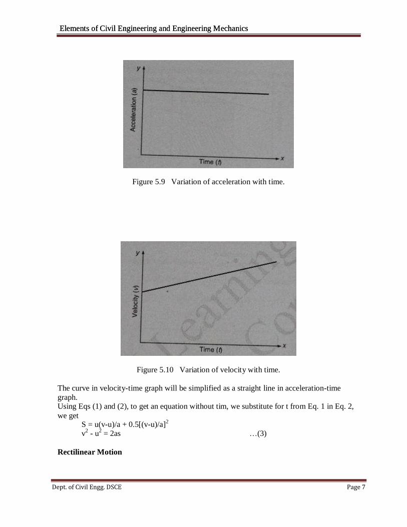
Acceleration-time graph: It is a plot of acceleration versus time graph as shown in Figure 5.9 It is seen that die acceleration is constant with respect to time t. The same can be connected to velocity-time graph (Figure 5.6), wherein the velocity variation is constant. The coordinates in acceleration-time graph show the area under the velocity-time curve.
In case of Figure 5.10, it is seen that the acceleration line in acceleration-time plot, it shows the variation of acceleration to be uniform.
Elements of Civil Engineering and Engineering Mechanics Elements of Civil Engineering and Engineering Mechanics
Dept. of Civil Engg. DSCE Page 7
Figure 5.9 Variation of acceleration with time.
Figure 5.10 Variation of velocity with time.
The curve in velocity-time graph will be simplified as a straight line in acceleration-time
graph. Using Eqs (1) and (2), to get an equation without tim, we substitute for t from Eq. 1 in Eq. 2,
we get
S = u(v-u)/a + 0.5[(v-u)/a]2
v2
- u2
= 2as …(3)
Rectilinear Motion
Elements of Civil Engineering and Engineering Mechanics Elements of Civil Engineering and Engineering Mechanics
Dept. of Civil Engg. DSCE Page 8
When a particle or a body moves along a straight line path, then it is called linear motion or rectilinear motion.
Equation of motion along a straight line v= u + at
v2
- u2
= 2as s = ut + 0.5at
Example 1: The motion of a particle is given by the equation x = t3
– 3t2
-9t + 12. Determine the time, distance travelled and acceleration of particle when velocity becomes zero. Solution
X = t3-3t
2-9t+l2 (1)
Differentiating Eq. (1) with respect to 'x', we get
v= dx/dt = 3t2-6t-9 (2)
when v = 0 The above equation is in the form of and the solution is
ax2+bx+c=0
x= -b±√(b2-4ac)/2a (3)
substituting the respective values in Eq. (3), we get
t = -1 or t = 3 s (negative value of t can be discarded) Substitute t = 3 s in (1), we get
x = -15 m Differentiating Eq. (2), we get
a =12 m/s2
Example 2: The motion of a particle is defined by the relation x = t
3- 9t
2 + 24t - 6. Determine
the position, velocity and acceleration when t = 5 s. Solution
x=t3-9t
2+24t-6 (1)
Differentiating Eq. (1), we get dx/dt=v = 3t
2-18t + 2 (2)
Differentiating Eq. (2). we get
d2x/dt
2 = a =6t -18
Substitute t = 5 s in Eqs. (1), (2) and (3), we get
x = 14 m v = 9 m/s a =12 m/s2
Elements of Civil Engineering and Engineering Mechanics Elements of Civil Engineering and Engineering Mechanics
Dept. of Civil Engg. DSCE Page 9
Example 3: A car is moving with a velocity of 15 m/s. The car is brought to rest by applying
brakes in 5 s. Determine (i) Retardation (ii) Distance travelled by the car after applying the
brakes.
Solution (i) Retardation We know that v = u + at
0= 15 + ax5
a = -3 m/s2
(ii) Distance travelled by the car after applying the brakes.
We know that
s = ut + 0.5at2
s= 15x5+ 0.5x(-3)x(5)2
s = 37.5m
MOTION UNDER GRAVITY
We know that everybody on the earth experiences a force of attraction towards the centre of
the earth is known as gravity. When a body is allowed to fall freely, it is acted upon by
acceleration due to gravity and its velocity goes on increasing until it reaches the ground. The
force of attraction of the earth that pulls all bodies towards the centre of earth with uniform
acceleration is known as acceleration due to gravity. The value of acceleration due to gravity is constant in general and its value is considered to be 9.81 m/s
2 and is always directed
towards the centre of earth. Acceleration due to gravity is generally denoted by 'g'. When the body is moving vertically downwards, the value of g is considered as positive and if the body is projected vertically upwards, then acceleration due to gravity is considered as
negative. Evidently, all equations of motion are applicable except by replacing unifor m
acceleration V with acceleration due to gravity 'g1 and are written as (i) When a body is projected vertically downward, under the action of gravity, the equations of motion are
v = u + gt v
2 = u
2 + 2gh
h = ut + 0.5gt2
(ii) When a body is projected vertically upward, under the action of gravity, the equations of
motion are v = u-gt v
2 = u
2 - 2gh
h = ut -0.5gt2
Example 4: A ball is thrown vertically upward into air with an initial velocity of 35 m/s. After
3 s another ball is thrown vertically. What initial velocity must be the second ball has to pass the first ball at 30 m from the ground.
- Solution Consider the first ball, we know that
h = u1t-0.5gt2
30 = 35t – 0.5*9.81*t2
t2
– 7.135t + 6.116 = 0 t = 6.138 s
Elements of Civil Engineering and Engineering Mechanics Elements of Civil Engineering and Engineering Mechanics
Dept. of Civil Engg. DSCE Page 10
Consider the second ball
t2 = (6.138 -3) = 3. 138s h = u2t2 – 0.5gt2
2
h = 30 m u2 = 24.91m/sec
CURVILINEAR MOTION
Introduction
When a moving particle describes a path other than a straight line is said be a particle in
curvilinear motion. If the curved path lies in a single plane is called plane curvilinear motion.
Most of the motions of particles encountered in engineering practices are of this type.
Curvilinear Motion in Cartesian Coordinates
In Cartesian coordinates two axes of reference will be chosen. To define the position of particle at any instant of time we have to choose a reference axis namely A and y.
Let, P be the position of particle at any instant of time t
'P1' be the new position at an instant of time (t + Δt) from origin. Join O to P and O to P1
Let r be the position vector of P having magnitude and direction. r1 be the position vector P1
Δr be the rate of change in displacement amount over a time Δt Average velocity over a time Δt = Δr/Δt
Figure 5.11
Velocity of particle is vector tangent to the path of panicle'
Elements of Civil Engineering and Engineering Mechanics Elements of Civil Engineering and Engineering Mechanics
Dept. of Civil Engg. DSCE Page 11
x
Let, Δx be the distance travelled in x direction Δy be the distance travelled in y direction
Velocity in 'x' direction = vx = dx/dt
Velocity in y direction = vy = dv/dtResultant velocity = v = \/(v
2 + vu
2)
Elements of Civil Engineering and Engineering Mechanics Elements of Civil Engineering and Engineering Mechanics
Dept. of Civil Engg. DSCE Page 12
Normal and tangential component of acceleration: Velocity of moving particle is always vector tangential to the path of particle. But acceleration is not tangential to path. But it is convenient to resolve the acceleration along tangential and normal direction.
Figure 5.11
Tangential acceleration = at = dv/dt Normal acceleration = an = (v
2/ρ)ρ = r
Where 'ρ' is the radius of curvature.
From the above expression it is evident that tangential component of acceleration is equal the
rate of change of velocity with respect to time. Normal component of acceleration is equal to
the square of velocity divided by the radius of curvature.
Example 6: The motion of a particle is described by the following equation x = 2(t + 1 )2
, y =
2(t + 1) -2
. Show that path travelled by the particle is rectangular hyperbola. Also find the velocity and acceleration of particle at t = 0 Solution To find the path travelled, we know that
x = 2(t+1)2
y = 2(t+1)2
Multiplying the two equation xy = 2 [xy = constant]
This represents a rectangular hyperbola
We know x = 2(t + 1)2
Component of velocity in x direction vx= 2 x 2(t + 1)
Component of acceleration in x direction ax = d2x/db
2 = 2x2 = 4 m/s
2
When t = 0, vx = 4 m/s2
ax = 4 m/s2
We know y = 2(t + 1)-2
Component of velocity in y direction
Elements of Civil Engineering and Engineering Mechanics Elements of Civil Engineering and Engineering Mechanics
Dept. of Civil Engg. DSCE Page 13
x y
vy = dy/dt = 2(-2)(t+1)-3
= -4(t+1)-3
Cornponent of acceleration in y direction
ay = d2y/dt
2 = -12(t+1)
-4
When t = 0
v y = 4m/s ay = 12m/s
velocity = v = √(v 2
tan Ѳ = vy/vx = -1
Ѳ = 45o
+ v 2)
2 2 2Acceleration = a = √(ax
α = 71.6o
+ ay ) = 12.65 m/s
CURVILINEAR MOTION IN POLAR COORDINATES
The curvilinear motion of particle can be expressed in terms of rectangular components and components along the tangent and normal to the path of particle.
In certain problems the position of particle is more conveniently described by its polar
coordinates. In that case it is much simpler to resolve the velocity and acceleration of particle
into components that are parallel and perpendicular to the position vector V of the particle.
These components are called radial and transverse components.
Figure 5.12
Consider a collar P sliding outward along a straight rod OA, which itself is rotating about fixed point O. It is much convenient to define the position of collar at any instant in terms of
Elements of Civil Engineering and Engineering Mechanics Elements of Civil Engineering and Engineering Mechanics
Dept. of Civil Engg. DSCE Page 14
distance r from the point 'O' and angular position 'Ѳ' of rod OA with x axis.
Thus polar coordinates of point P these are (r, Ѳ).
It can be shown that the radial and transverse components of velocity are v r = r (Radial component directed along position vector r)
Transverse component
vѲ = rѲ(Transverse component directed along the normal to the position vector r)
Total velocity = v = √(vr2
+ vѲ2)
Radial component of acceleration ar = r..
- r(Ѳ)2
Figure 5.13
Transverse component of acceleration aѲ = rѲ.. + 2 rѲ
Total acceleration = a = √(ar2
+aѲ2)
The component of velocity and acceleration are related as
ar = vr - vѲѲ ar = vѲ - vrѲ
From the above equation it can be seen that 'ar' is not equal to vr and aѲ' is not equal to vѲ
It would be noted that radial component of velocity and acceleration are taken to the positive in the same sense of position vector r. Transverse components of velocity and acceleration are taken to the positive if pointing
towards the increasing value of Ѳ. To understand the physical significance of above results let us assume the following two situations.
(i) If r is of constant length and Ѳ varies. Then r reduces to rotation along circular path.
r = constant r = r = 0
vѲ = rѲ vr = r = 0
Elements of Civil Engineering and Engineering Mechanics Elements of Civil Engineering and Engineering Mechanics
Dept. of Civil Engg. DSCE Page 15
aѲ = rѲ ar = -r(Ѳ)
2
(-ve sign indicates that ar is directed opposite to the sense of position vector 'r' or towards 'O')
(ii) If, only r varies and Ѳ constant it then resolves a rectilinear motion along a fixed
Example 7: The plane curvilinear motion of particle is defined in polar coordinates by r = t3/3
+ 2t and Ѳ = 0.3t2
Find the magnitude of velocity, acceleration of path when t = 1 s.
Solution: Equations of motion are
r = t3/3 + 2t & Ѳ = 0.3t
2
Evaluating Ѳ, dѲ/dt. d2Ѳ/dt2
Ѳ =0.3t2
dѲ/dt = 2*0.3t d2Ѳ/dt2 = 0.6
At t = 1s
Ѳ = 0.3 rad
dѲ/dt = 0.6 rad
d2Ѳ/dt2 = 0.6 rad/s2
r = 2.33m dr/dt
= 3m/s d2r/dt
2
= 2m/s2
Velocity
Vr = dr/dt = 3m/s
vѲ = rѲ = 2.33*0.6
PROJECTILES
Whenever a particle is projected upwards with some inclination to the horizontal (but not
vertical), it travels in the air and traces a parabolic path and falls on the ground point (target)
other than the point of projection. The particle itself is called projectile and the path traced by
the projectile is called trajectory.
Elements of Civil Engineering and Engineering Mechanics Elements of Civil Engineering and Engineering Mechanics
Dept. of Civil Engg. DSCE Page 16
Terms used in projectile
Figure 5.14
1. Velocity of projection (u): It is the velocity with which projectile is projected in the
upward direction with some inclination to the horizontal.
2. Angle of projection (α): It is the angle with which the projectile is projected with respect to horizontal.
3. Time of flight (T): It is the total time required for the projectile to travel from the point of
projection to the point of target.
4. Horizontal range (R): It is the horizontal distance between the point of projection and target point.
5. Vertical height (h): It is the vertical distance/height reached by the projectile from the
point of projection.
Some relations
Time of flight: Let T be the time of flight. We know that the vertical ordinate at any point on the path of
projectile after a time T is given by
y = (u sin α)t – 0.5gt2
When the projectile hits the ground, say at B: y = 0 at t = T Above equation becomes
0 = (u sin α)t- 0.5gt2
(u sin α) = 0.5gt T = (2u sin α)/g
Horizontal range of the projectile: During the time of flight, the horizontal component of velocity of projectile = u cos α
{Horizontal distance of the projectile} = R= {Horizontal component of velocity of projection}
{Time of flight} = u cos α x T
Elements of Civil Engineering and Engineering Mechanics Elements of Civil Engineering and Engineering Mechanics
Dept. of Civil Engg. DSCE Page 17
R = (u cos α *2u sin α)/g = (u2
sin (2α))/g
sin (2 α) will be maximum only when sin 2 α = 1
sin 2 α = sin 90 or α = 45° Hence maximum horizontal range is given by
Rmax = (u2
sin 90)/g = u2/g
Maximum height attained by the projectile: When the projectile reaches its maximum height,
vertical component of velocity of projection becomes zero.
V2
– u2
= 2gs
0 – u2
sin2
α = -2ghmax
hmax = u2
sin2
α/ 2g
Time required to reach the maximum height is given by
v = u + at
0 = u sin α - gt t = u sin α / g
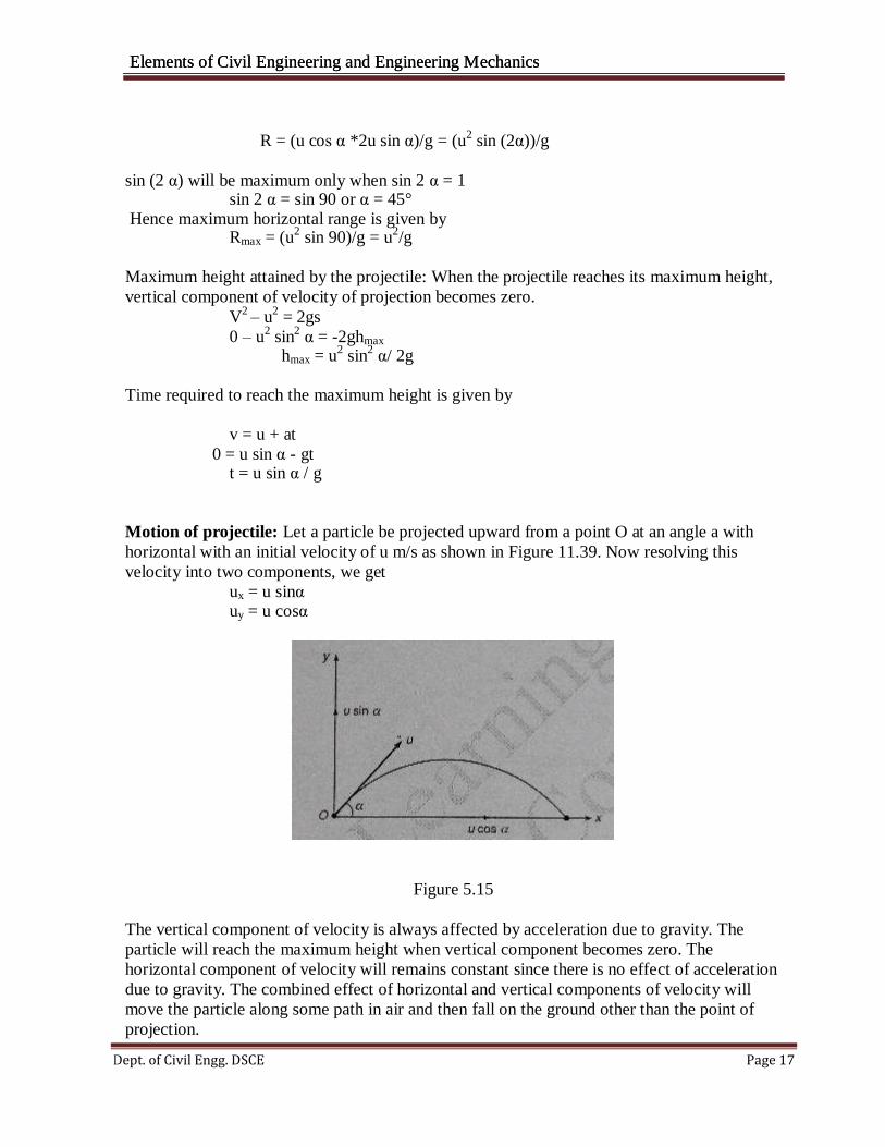
Motion of projectile: Let a particle be projected upward from a point O at an angle a with
horizontal with an initial velocity of u m/s as shown in Figure 11.39. Now resolving this
velocity into two components, we get
ux = u sinα uy = u cosα
Figure 5.15
The vertical component of velocity is always affected by acceleration due to gravity. The
particle will reach the maximum height when vertical component becomes zero. The
horizontal component of velocity will remains constant since there is no effect of acceleration
due to gravity. The combined effect of horizontal and vertical components of velocity will
move the particle along some path in air and then fall on the ground other than the point of
projection.
Elements of Civil Engineering and Engineering Mechanics Elements of Civil Engineering and Engineering Mechanics
Dept. of Civil Engg. DSCE Page 18
Equation for the path of projectile (Trajectory equation): Let a particle is projected at a certain
angle from point O. The particle will move along a certain path OPA in the air and will fall
down at A. Let u = velocity of projection
α = angle of projection After t seconds, let a particle reach any point 'P' with x and y as coordinates as shown in Figure 5.16 We know that, horizontal component of velocity of projection = u cosα
Vertical component of velocity of projection = u sin α
Therefore, x = u cosαt
y = u sin αt – 0.5gt2
From Eq. (1)
t = x/(u cos α)
substitute in Eq. (2), we get
y = u sinα[x/(u cosα)] – 0.5g[x/ucosα]2
y = x tanα – [gx2/(2u
2cos
2α)]
Figure 5.16
Example 8: A particle is projected at an angle of 60° with horizontal. The horizontal range of particle is 5 km. Find
(i) Velocity of projection (ii) Maximum height attained by the particle
Solution Data given; R = 5 km = 5000 m, g = 9.81 m/s2 and α = 60° To find: u and hmax
We know that R = (u
2 sin 2α)/g …………(1)
Substituting the known values in Eq. (1), we get
Elements of Civil Engineering and Engineering Mechanics Elements of Civil Engineering and Engineering Mechanics
Dept. of Civil Engg. DSCE Page 19
u = 237.98 m/s
Again, maximum height attained by the particle hmax = (u
2 sin α)/2g = 2164.9m
Motion of a body thrown horizontally from a certain height into air
The figure shows a body thrown horizontally from certain height 'H' into air. At 'B' there is
only horizontal component of velocity. As the body moves in the air towards the ground, the
body has both horizontal and vertical components of velocity.
The horizontal component of velocity from B to A remains constant and will be equal to u.
But the vertical component of velocity in the downward direction will be subjected to
gravitational force and hence will not be a constant.
Resultant velocity = R = √(u2 + v2) & Ѳ = tan-1
(v/u)
(i) Vertical downward distance travelled by the body is given by
H = (vertical component of velocity at B)t + 0.5gt2
Figure 5.17
(ii) The horizontal distance travelled by the body
R = (horizontal component of velocity at B)t
R = ut (iii) The vertical component of velocity at point A is obtained from the equation
v = u + gt or v = gt Resultant Velocity at A = R = √(u2 + v2)
Elements of Civil Engineering and Engineering Mechanics Elements of Civil Engineering and Engineering Mechanics
Dept. of Civil Engg. DSCE Page 20
Example 9: An aircraft is moving horizontally at a speed of 108 km/h at an altitude of 1000 m
towards a target on the ground releases a bomb which hits the target. Estimate the horizontal
distance of aircraft from the target when it release a bomb. Calculate also the direction and
velocity with which bomb hits the target.
Solution Speed of aircraft = (108xl00)/(60x30) = 30m/s
Horizontal velocity of bomb = u = 200 m/s
Height H= 1000m
Let t be the time required for the bomb to hit the target
We know that
H = 0.5gt2
1000 .5 x 9.81 x t2
or t = 14.278 s
(i) Horizontal distance of aircraft from the target when it releases a bomb.
We know that R = u x t = 30 x 14.278 = 428.57 m
(ii) Velocity with which bomb hits the target. Vertical component of velocity = v = gt = 9.8 1 x 14.278 = 1 39.9 m/s Horizontal component of velocity = u = 30 m/s