115
MODULE – I

MODULE – I

1. STEPPING MOTORS
1.1 Introduction
A stepping motor is also known as stepper motor or step motor. A stepper motor is
a brushless DC motor whose rotor rotates in discrete angular displacements when its stator
windings are energised in a programmed manner. Rotation occurs because of magnetic
interaction between rotor poles and poles of the sequentially energised stator winding. The
rotor has no electrical windings, but has salient and /or magnetised poles.
It is an electrical motor which converts a digital electric input into mechanical
motion. As the angular rotation is dependent on the number of input pulses, the motor is
suitable for controlling the position by controlling the number of input pulses. Compared
with other devices that can perform the same or similar functions, a control system using a
stepping motor has several significant advantages as follows:
(1) No feedback is normally required for either position control or speed control.
(2) Positional error is non-cumulative.
(3) Stepping motors are compatible with modern digital equipment.
For these reasons, various types and classes of stepping motor have been used in
computer peripherals and similar systems. Some applications are in printers, graph plotters,
tape driver, disk drives, machine tools, X-Y recorders, robotics, space vehicles, IC
fabrication and electric watches.
Generally, stepping motors are operated by electronic circuits, mostly on a DC
power supply. The stepping motor is a unique motor in this respect as compared with
conventional electric motors, which are mostly driven directly from a power supply.
Moreover, stepping motors find their applications in speed and position controls without
expensive feedback loops. This driving method is referred to as the open-loop drive.
Nowadays, transistors are used as electronic switches for driving a stepping motor, and
switching signals, are generated by digital ICs or a microprocessor (see Fig. 1.1).
Fig 1.1: Modern driving system for a stepping motor
Open-loop control is an economically advantageous driving method, yet it is not free
from some limitations. For example, the revolution of the rotor becomes oscillatory and
unstable in certain speed ranges, and due to this behavioural characteristic, the speed and
acceleration of a stepping motor controlled in the open-loop scheme cannot be as fast as a
DC motor driven in a feedback-control scheme. Hence, in trying to expand the ranges of
applications, the suppression of oscillations is a fundamental problem to be solved. Closed-
loop control is a very effective driving method being free from instability and capable of
quick acceleration.

1.2 CLASSIFICATION OF STEPPER MOTORS
As far as construction is concerned stepper motors may be divided into two
major groups
1. Without permanent magnet (PM)
a) Single stack
b) Multi stack
2. With permanent magnet
a) Claw pole motor
b) Hybrid motors
1.2.1 Single Stack Variable Reluctance Stepper Motor
Construction:
The VR stepper motor is characterized by the fact that there is no permanent
magnet either on the rotor or the stator. The construction of a 3 phase VR stepper motor
with 6 poles on the stator and 4 poles on the rotor is shown in fig. 1.2.
Fig. 1.2: Cross sectional view of variable reluctance motor
The stator is made up of silicon steel stampings with inward projected even or odd
number of poles or teeth (usually the number of poles of stator is an even number). Each
and every stator pole carries a field coil or exciting coil. In case of even number of poles the
exciting coils of opposite poles are connected in series. The two coils are connected such
that their MMF get added. The combination of two coils is known as phase winding.
The rotor is also made up of silicon steel stampings with outward projected poles
and it does not have any electrical windings. The number of rotor poles should be different
from that of stator in order to have self starting capability and bi-directional rotation. The
width of rotor teeth should be same as stator teeth. Solid silicon steel rotors are extensively
employed. Both the stator and rotor materials must have high permeability and be capable of
allowing a high magnetic flux to pass through them even if a low magnetomotive force is
applied.
Electrical connection:
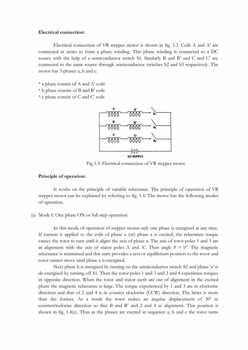
Electrical connection of VR stepper motor is shown in fig. 1.3. Coils A and A‘ are
connected in series to form a phase winding. This phase winding is connected to a DC
source with the help of a semiconductor switch S1. Similarly B and B‘ and C and C‘ are
connected to the same source through semiconductor switches S2 and S3 respectively. The
motor has 3-phases a, b and c.
* a phase consist of A and A‘ coils
* b phase consist of B and B‘ coils
* c phase consist of C and C‘ coils
Fig 1.3: Electrical connection of VR stepper motor
Principle of operation:
It works on the principle of variable reluctance. The principle of operation of VR
stepper motor can be explained by referring to fig. 1.4. The motor has the following modes
of operation.
(a) Mode I: One phase ON or full step operation:
In this mode of operation of stepper motor only one phase is energised at any time.
If current is applied to the coils of phase a (or) phase a is excited, the reluctance torque
causes the rotor to turn until it aligns the axis of phase a. The axis of rotor poles 1 and 3 are
in alignment with the axis of stator poles A and A‘. Then angle θ = 00. The magnetic
reluctance is minimised and this state provides a rest or equilibrium position to the rotor and
rotor cannot move until phase a is energised.
Next phase b is energised by turning on the semiconductor switch S2 and phase ‗a‘ is
de-energised by turning off S1. Then the rotor poles 1 and 3 and 2 and 4 experience torques
in opposite direction. When the rotor and stator teeth are out of alignment in the excited
phase the magnetic reluctance is large. The torque experienced by 1 and 3 are in clockwise
direction and that of 2 and 4 is in counter clockwise (CCW) direction. The latter is more
than the former. As a result the rotor makes an angular displacement of 300 in
counterclockwise direction so that B and B‘ and 2 and 4 in alignment. This position is
shown in fig. 1.4(c). Thus as the phases are excited in sequence a, b and c the rotor turns

with a step of 300 in counter clockwise direction. The direction of rotation can be reversed
by reversing the switching sequence of the phases i.e. a, c and b etc. The direction of
rotation depends on the sequence in which phase windings are energised and is independent
of the direction of currents through the phase winding.
Fig 1.4: Step motions as switching sequence process in a 3-phase VR motor
The truth table for mode I operation in counter clockwise and clockwise directions are given
in tables 2.1 and 2.2 respectively.

(b) Mode II: Two phase on mode:
In this mode two stator phases are excited simultaneously. When phases a and b are
energised together, the rotor experiences torque from both phases and comes to rest in a
point midway between the two adjacent full step position. If the phases b and c are excited,
the rotor occupies a position such that angle between AA‘ axis of stator and 1-3 axis of rotor
is equal to 45°. To reverse the direction of rotation switching sequence is changed i.e. a and
b, a and c etc. The main advantage of this type of operation is that torque developed by the
stepper motor is more than that due to single phase ON mode of operation.
Truth table for mode II operation in counter clockwise and clockwise direction are given in
table 2.3 and 2.4 respectively.

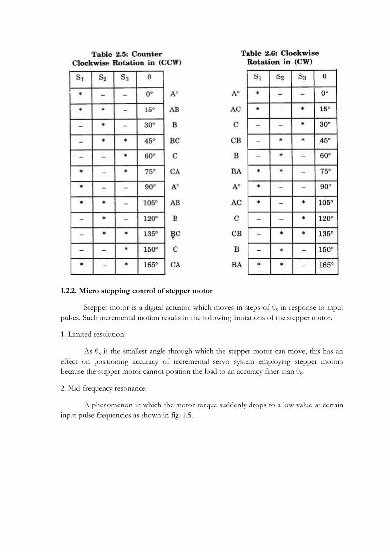
(c) Mode III: Half step mode:
In this type of mode of operation one phase is ON for some duration and two
phases are ON during some other duration. The step angle can be reduced from 30° to 15°
by exciting phase in sequence a, a + b, b, b + c, c etc. The technique of shifting excitation
from one phase to another (i.e.) from a to b with an intermediate step of a + b is known as
half step and is used to realise smaller steps. Continuous half stepping produces smoother
shaft rotation.
The truth table for mode III operation in counter clockwise and clockwise direction
are given in tables 2.5 and 2.6 respectively.
1.2.2. Micro stepping control of stepper motor
Stepper motor is a digital actuator which moves in steps of θS in response to input
pulses. Such incremental motion results in the following limitations of the stepper motor.
1. Limited resolution:
As θS is the smallest angle through which the stepper motor can move, this has an
effect on positioning accuracy of incremental servo system employing stepper motors
because the stepper motor cannot position the load to an accuracy finer than θS.
2. Mid-frequency resonance:
A phenomenon in which the motor torque suddenly drops to a low value at certain
input pulse frequencies as shown in fig. 1.5.

Fig. 1.5: Mid-frequency resonance
A new principle known as microstepping control has been developed with a view of
overcoming the above limitations. It enables the stepper motor to move through a tiny
microstep of size ∆θS0 << θS
0 , full step angle in response to input pulses.
Principle of microstepping:
Assume a two phase stepper motor operating in ―One phase ON‖ sequence.
Assume also that only B2 winding is ON and carrying current IB2 = IR the rated phase
current. All the other windings are OFF. In this state the stator magnetic field is along the
positive real axis as shown in fig. 1.6 (a). Naturally the rotor will also be in θ= 00 position.
When the next input pulse comes, B2 is switched OFF while A1 is switched ON. In
this condition IAl = IR while all the phase currents are zero. As a result the stator magnetic
field rotates through 90° in counter clockwise direction as shown in fig. 1.6(a).
The rotor follows suit by rotating through 90° in the process of aligning itself with
stator magnetic field. Thus with a conventional controller the stator magnetic field rotates
through 90° when a new input pulse is received causing the rotor to rotate through full step.
However in microstepping we want the stator magnetic field to rotate through a
small angle θS << 900 in respect to input pulse. This is achieved by modulating the current
through B2 and A1 winding as shown in fig. 1.6 (b) such that
IB2 = IRcosθ
while IAl = IR sinθ
Then the resulting stator magnetic field will be at an angle θ0 with respect to the
positive real axis. Consequently the rotor will rotate through an angle θ0 << 90°.
This method of modulating currents through stator windings so as to obtain rotation
of stator magnetic field through a small angle θ0 to obtain microstepping action is known as
the micro stepping. Although currents IRcosθ and IRsinθ is flowing through individual stator
windings, there resultant is IR. The resulting stator magnetic field has the same magnitude.

Consequently the stepper motor develops the same torque as developed under one phase
ON sequence.
There is no reduction in motor torque on account of microstepping.
Fig. 1.6: Principle of microstepping
Advantages:
1. Improvement in resolution by a factor MSR Micro Stepping Ratio
MSR = θS /∆θS
The values of MSR are 5, 10, 25 and in powers of 2 upto 128. The smallest angle
through which the motor rotates per input pulse is
∆θ =1
𝑀𝑆𝑅 θS
2. Rapid motion at a microstepping rate (MFs) which is MSR times the full stepping rate
(Fs).
3. DC motor like performance: Under microstepping control, the stepper motor moves
rapidly at microstepping rate in tiny micro steps of size ∆θ. The resulting motion is so
smooth that it is practically in distinguishable from continuous motion of the DC motor.
4. Elimination of mid frequency resonance: On account of smooth and rapid motion under
microstepping control, mid-frequency resonance are not excited.
1.2.3. Multistack variable reluctance stepper motor:
These are used to obtain smaller step sizes, typically in the range of 2° to 15°.
Although three stacks are common a multistack motor may employ as many as seven stacks.
This type is also known as the cascade type. A cutaway view of a three stack motor is shown
in fig. 1.7.

Fig. 1.7: Construction of multi-stack VR motor.
A multistack (or m-stack) variable reluctance stepper motor can be considered to be
made up of ‗m‘ identical single stack variable reluctance motors with their rotors mounted
on a single shaft. The stators and rotors have the same number of poles (or teeth) and
therefore same pole (tooth) pitch. For a rn-stack motor, the stator poles (or teeth) in all m
stacks are aligned, but the rotor poles (teeth) are displaced by 1/rn of the pole pitch angle
from one another. All the stator pole windings in a given stack are excited simultaneously
and, therefore the stator winding of each stack forms one phase. Thus the motor has the
same number of phases as number of stacks.
Fig 1.8: Cross-section of a 3-stack, VR stepper motor parallel to the shaft
Figure 1.8 shows the cross section of a three stack (3-phase) motor parallel to the
shaft. In each stack, stator and rotors have 12 poles (teeth). For a 12 pole rotor, pole pitch is
300 and therefore, the rotor poles (teeth) are displaced from each other by l/3rd of the pole
pitch or 100. The stator teeth in each stack are aligned. When the phase winding A is excited
rotor teeth of stack A are aligned with the stator teeth as shown in fig. 1.9.

When phase A is de-energised and phase B is excited the rotor teeth of stack B are
aligned with stator teeth. This new alignment is made by the rotor movement of 100 in the
anticlockwise direction. Thus the motor moves one step (equal to 1/3 pole pitch) due to
change of excitation from stack A to stack B
Next phase B is de-energised and phase C is excited. The rotor moves by another
step of 1/3rd of pole pitch in the anticlockwise direction. Another change of excitation from
stack C to stack A will once more align the stator and rotor teeth in stack A. However
during this process (A — B — C — A) the rotor has moved one rotor tooth pitch.
Fig. 1.9: Position of stator & rotor teeth of 3 stack VR motor
Let Nr be the number of rotor teeth and ‗m‘ the number of stacks or phases, then
Tooth pitch Tp = 360/Nr
Step Angle α = 360/ mNr
In this case,
Tooth pitch Tp = 360/12 = 30
Step angle α = 360/ (3*12) = 10
The variable reluctance motors, both single and multi stack types, have high torque
to inertia ratio. The reduced inertia enables the VR motor to accelerate the load factor.
Step angle also given by α =𝑁𝑠−𝑁𝑟
𝑁𝑠𝑁𝑟 * 360
where Ns — Stator poles or stator teeth.
Nr —Rotor poles or rotor teeth
1.2.4 Permanent Magnet Stepper Motor
The permanent magnet stepper motor has a stator construction similar to that of
single stack variable reluctance motor. The rotor is cylindrical and consists of permanent
magnet poles made of high retentivity steel. The field coils of opposite poles are connected
in series to have one phase winding.
Principle of operation:
(a) Single phase energisation:
Two phase 4 pole stepper motor can be considered. When phase A is energised with
positive voltage applied, it sets up a magnetic field FA in the direction as shown in fig 1.10(a).
The rotor will position itself in such a way as to lock its N-pole to stator S-pole and vice
versa.
Now phase A is de-energized and phase B is energized by applying positive voltage
to it. Now FA will be zero and stator magnetic field FB will be in the direction as shown in
fig. 1.10(b). Then the rotor moves through 90° (step angle) in counter clockwise direction so
as to align with the stator field axis FB. Rotor will position in such a way that its S-pole lock
with stator N-pole.
Then phase B is de-energized and a reverse voltage (-V) is applied to phase A. This
results in the stator magnetic field FA as shown in fig. 1.10(c). Now the rotor rotates through
900 in counter clockwise direction and aligns with FA as shown in fig. 1.10(c).
Now phase A is de-energized and a reverse voltage (-V) is applied to phase B. This
results in the stator magnetic field FB as shown in fig. 1.10 (d). Rotor further rotates by 900 in
counter clockwise direction and align with FB vector.
The above sequence is single phase energisation sequence in which only one stator
winding is energised at any time.
(b) Two phase energisation:
In this initially positive voltage is applied to phase A. This gives rise to a stator
magnetic field vector FA as shown in fig. 1.10(a). The rotor N-pole lock with S-pole of
stator and vice versa.

With winding A energized as before, positive voltage is applied to phase B causing
pole B to be N-pole and B‘ to be S-pole. This produces another stator magnetic field FB as
shown in fig. 1.10(e). The resulting stator magnetic field will be + 45 degree from its former
position. Hence rotor will move through a fixed angle of +45 degree as shown in fig.
1.10(e).
With winding B energized as before winding A be de-energized, FA becomes zero,
leaving FB as before. The rotor, will move through another 45° to align itself with FB as in
fig. 1.10(b).
With phase B energized as before, a negative voltage is applied to phase A. This
reverses stator magnetic field FA as in fig. 1.10(f). The resulting vector F shifts by another
450 causing the rotor to follow suit.
With phase A energized as before phase B is de-energized the vector -FA alone be
there and FB = 0. The rotor occupies the position as shown in fig. 1.10(c).
With phase A energized as before, negative voltage is applied to phase B, the rotor
occupies the position as shown in fig. 1.10(g).
With B phase energized as before as A phase is de-energized, the rotor occupies the
position as shown in fig. 1.10 (d).
With B phase energized as before and positive voltage applied to A. The resulting
vector F shifts the rotor by another 45° as shown in fig. 1.10(g).
Fig. 1.10 (a, b, c and d) corresponds to single phase energisation.
Fig. 1.10 (e, f, g and h) corresponds to two phase energisation.
Both the above sequences are four step sequence, since the rotor moves through 900.
With single phase sequence, rotor positions are 90°, 180°, 270° and 360°, while rotor
positions are 45°, 135°, 225° and 315° in the case of two phase sequence.
Fig. 1.10 (a to h) constitute 8-step sequence in which the rotor moves through 45°
per step. Here one and two phases are energized alternatively. This sequence is known as
mixed, hybrid or (1-2) sequence.

Fig 1.10: Principle of operation of PM motor
1.2.5. Hybrid Stepper Motor
Another type of stepping motor having permanent magnet in its rotor is the hybrid
motor. The term ―hybrid‖ derives from the fact that the motor is operated with the
combined principles of the permanent and variable reluctance motors, in order to achieve a
small step angle and a high torque from a small size. The stator core structure is the same as
or very close to that of variable reluctance motors. The important feature is the rotor
structure. A cylindrical or disk shaped magnet lies in the rotor core and it is magnetised
lengthwise to produce a unipolar field as shown in fig. 1.11(a). Each pole of the nagnet is
covered with uniformly toothed soft steel end caps. Teeth on the two end caps are
misaligned with respect to each other by a half toothed pitch. The toothed end caps are
normally made of laminated silicon steel. The magnetic field generated by stator coil is a
hetropolar field as shown in fig. 1.11(b).
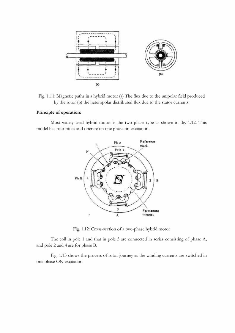
Fig. 1.11: Magnetic paths in a hybrid motor (a) The flux due to the unipolar field produced
by the rotor (b) the heteropolar distributed flux due to the stator currents.
Principle of operation:
Most widely used hybrid motor is the two phase type as shown in flg. 1.12. This
model has four poles and operate on one phase on excitation.
Fig. 1.12: Cross-section of a two-phase hybrid motor
The coil in pole 1 and that in pole 3 are connected in series consisting of phase A,
and pole 2 and 4 are for phase B.
Fig. 1.13 shows the process of rotor journey as the winding currents are switched in
one phase ON excitation.

Fig. 1.13: One-phase-on operation of a two-phase hybrid motor.
When the poles of phase A are excited, the teeth of pole 1 attract some of the rotor‘s
north poles, while the teeth of pole 3 align with rotor‘s south poles. Current is then switched
to phase B, the rotor will travel a quarter tooth pitch so that tooth alignment takes place in 2
and 4.
Next current is switched back to phase A but in opposite polarity to before, the
rotor will make another quarter tooth journey. The tooth alignment occurs in opposite
magnetic polarity to state 1.
When current is switched to phase B in opposite polarity, state (4) occurs as a result
of another quarter tooth pitch journey.
1.2.6: Claw Tooth PM Motor:
This is another type of stepping motor. This is also known as can-stack stepping
motor, as the stator of this motor consists of a sort of metal can. Teeth are punched out of a
circular metal sheet and the circle is then drawn into a bell shape. The teeth are then drawn
inside to form claw teeth. A stack of the stator is formed by joining two bell shaped casings
so that the teeth of both of them are intermeshed and the solenoidal coil is contained within
them. This type of motor shown in fig. 1.14.
Fig. 1.14: Cutaway diagram of a claw-poled PM motor.
The feature of the can-stack motor is that the stator teeth or claw-poles produce a
heteropolar magnetic field from a current flowing in the solenoid of the stator. As illustrated
in Fig. 1.15, the rotor‘s, cylindrical ceramic magnet (ferrite) is magnetized to produce a
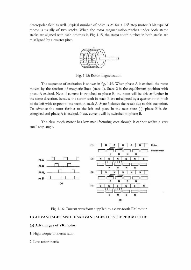
heteropolar field as well. Typical number of poles is 24 for a 7.5° step motor. This type of
motor is usually of two stacks. When the rotor magnetization pitches under both stator
stacks are aligned with each other as in Fig. 1.15, the stator tooth pitches in both stacks are
misaligned by a quarter pitch.
Fig. 1.15: Rotor magnetization
The sequence of excitation is shown in fig. 1.16. When phase A is excited, the rotor
moves by the tension of magnetic lines (state 1). State 2 is the equilibrium position with
phase A excited. Next if current is switched to phase B, the rotor will be driven further in
the same direction, because the stator teeth in stack B are misaligned by a quarter tooth pitch
to the left with respect to the teeth in stack A. State 3 shows the result due to this excitation.
To advance the rotor further to the left and place in the next state (4), phase B is de-
energised and phase A is excited. Next, current will be switched to phase B.
The claw tooth motor has low manufacturing cost though it cannot realize a very
small step angle.
Fig. 1.16: Current waveform supplied to a claw-tooth PM motor
1.3 ADVANTAGES AND DISADVANTAGES OF STEPPER MOTOR:
(a) Advantages of VR motor:
1. High torque to inertia ratio.
2. Low rotor inertia

3. Capable of high stepping rate, high speed slewing capabilities.
4. Ability to free wheel
5. Light weight
6. Three, four and five phase single and multistack models available.
(b) Disadvantages of VR motor:
1. No detent torque available when windings de-energised.
2. Exhibit mid-range resonance at some stepping rates under some drive condition.
3. Normally available in 3.6° to 300 step angle.
4. Low efficiency at low voltages and stepping rate.
(c) Advantages of PM motor:
1. Provides detent torque when winding de-energised
2. Less tendency to resonate
3. Higher holding torque capability
4. Better damping due to the presence of rotor magnet
5. High stepping rate capability.
6. High efficiency at lower speeds and lower stepping rates
(d) Disadvantages of PM motor:
1. Higher inertia and weight due to the presence of rotor magnet.
2. Performance affected by change in magnet strength.
3. Costlier than variable reluctance stepper motor.
Comparison between VR and PM stepper motor:
Comparison between variable reluctance and permanent magnet stepper motors are given in
table 2.7

1.4. Windings Used In Stepper Motor
Solenoid coils are used in multi-stack VR and claw-poled PM motors. On the other
hand, for hybrid motors and single stack VR motors, the monofilar winding or bifilar
winding is used. In the former a single wire is wound a number of times on a single pole. In
the latter, two overlapping wires are wound as one wire as shown in Fig. 1.17, and these two
wires are separated from each other at the terminals to keep them as independent wires. If
one coil belongs to Ph1, the other belongs to Ph3. Likewise, if one belongs to Ph2, the other
belongs to Ph4.
Fig. 1.17: Bifilar winding
One of the purposes of the bifilar winding is to energize a stator pole by alternating
magnetic polarity. Excitation of a phase may be performed by one of the three schemes
shown in Fig. 1.18. In the monofilar winding in (a), the magnetic polarity on excitation is
always north or south, which implies that the polarity cannot be switched. This excitation
method is termed unipolar excitation. In circuit (b), the direction of current in the coil can
switched because of a bridge circuit. However, four transistors are required for each phase.
This method is referred to as bipolar excitation. Circuit (c) involves a pair of bifilar windings
and two transistors, by which the stator pole can be excited in any magnetic polarity, for one

coil is used to excite a north pole while the other excites a south pole. Two coils wound in
bifilar scheme are magnetically coupled when either is excited. If two independent coils are
provided instead of bifilar windings, inductance difference will appear between the two coils
and positioning accuracy will be degraded.
Fig. 1.18: Three fundamental exciting circuits
The efficiency of a permanent-magnet motor operated in the alternating polarity
mode is higher than the efficiency attained in the unipolar drive mode.
1.5. Modes Of Excitation
Excitation method is the most basic one and often used for analysing fundamental
theoretical problems. However several different methods of excitation are in use today.
1.5.1 Single phase excitation:
Table 2.8 shows the sequences of a single phase excitation mode for three and four
phase VR motors. In this mode only one phase is excited at a time. The shaded parts in the
table represent the excited state and unshaded parts show the phases to which current is not
supplied and so are not excited.

When a motor revolves clockwise in the excitation sequence of Ph1 -Ph 2 - Ph 3..., it will
revolve counter clock wise direction by simply reversing the sequence to Ph 3 - Ph 2 - Ph 1..
Single phase excitation is also known as ‗one phase on drive‘.
1.5.2. Two phase excitation:
The operation of a motor in which two phases are always excited is called two phase
on operation. Excitation sequence are given is Table 2.9.
A big characteristic difference between the single phase on and two phase on
operation appears in the transient response as shown in fig. 1.19.
Fig. 1.19: Difference in single step response between the (a) single-phase and (b) two-phase
excitation.
In two phase on drive the oscillations damps out more quickly than in the case of
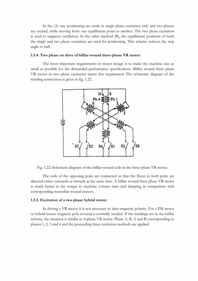
single phase on mode. This can be explained using fig. 1.20 and 1.21 as follows.
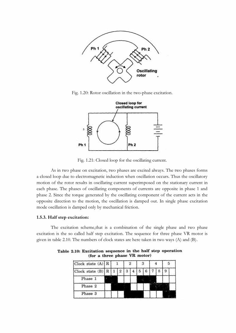
Fig. 1.20: Rotor oscillation in the two-phase excitation.
Fig. 1.21: Closed loop for the oscillating current.
As in two phase on excitation, two phases are excited always. The two phases forms
a closed loop due to electromagnetic induction when oscillation occurs. Thus the oscillatory
motion of the rotor results in oscillating current superimposed on the stationary current in
each phase. The phases of oscillating components of currents are opposite in phase 1 and
phase 2. Since the torque generated by the oscillating component of the current acts in the
opposite direction to the motion, the oscillation is damped out. In single phase excitation
mode oscillation is damped only by mechanical friction.
1.5.3. Half step excitation:
The excitation scheme,that is a combination of the single phase and two phase
excitation is the so called half step excitation. The sequence for three phase VR motor is
given in table 2.10. The numbers of clock states are here taken in two ways (A) and (B).
In the (A) way positioning are made in single phase excitation only and two phases
are excited, while moving from one equilibrium point to another. The two phase excitation
is used to suppress oscillation. In the other method (B), the equilibrium positions of both
the single and two phase excitation are used for positioning. This scheme reduces the step
angle to half.
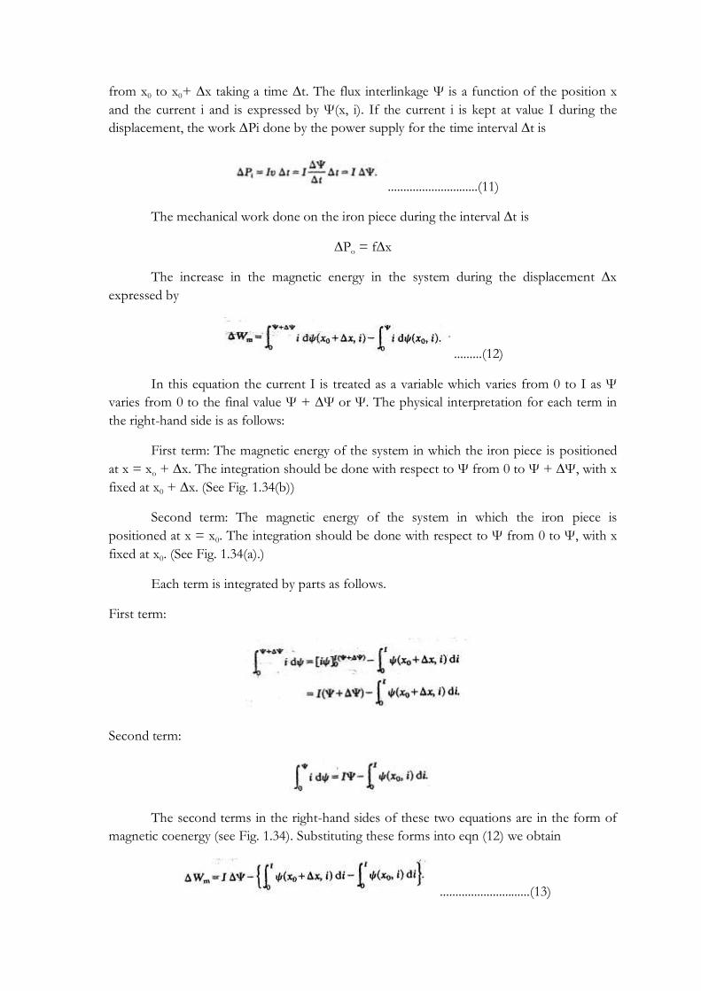
1.5.4. Two phase on drive of bifilar wound three-phase VR motor:
The most important requirements in motor design is to make the machine size as
small as possible for the demanded performance specifications. Bifilar wound three phase
VR motor in two phase excitation meets this requirement The schematic diagram of the
winding connection is given in fig. 1.22.
Fig. 1.22: Schematic diagram of the bifilar-wound coils in the three-phase VR motor.
The coils of the opposing poles are connected so that the fluxes in both poles are
directed either outwards or inwards at the same time. A bifilar wound three phase VR motor
is much better in the torque to machine volume ratio and damping in comparison with
corresponding monofilar wound motors.
1.5.5. Excitation of a two phase hybrid motor:
In driving a VR motor it is not necessary to alter magnetic polarity. For a PM motor
or hybrid motor magnetic pole reversal is normally needed. If the windings are in the bifilar
scheme, the situation is similar to 4-phase VR motor. Phase A, B, A and B corresponding to
phases 1, 2, 3 and 4 and the proceeding three excitation methods are applied.

Fig. 1.23: Bridge driver scheme for a two-phase stepping motor.
If each of phases A and B has a monopolar coil on each pole, the bridge circuit
shown in fig. 1.23 is suitable drive scheme for bipolar mode. One phase on, two phase on
and half step mode are available with the bridge circuit, the switching sequences and the
voltage waveforms applied to each phase are compared in table 2.11 and fig. 2.25.

It is known that 25-30 per cent improvements in power consumption are possible by
use of bipolar drive. The only drawback of the bridge drive is that it needs twice as many
transistors as the bifliar operation.
1.6. Single Phase Stepping Motor:
These are motors which are designed to be operated from a single phase supply.
They are widely used in watches and clocks, timers and counters. Present single phase
stepping motors use one or more (two) permanent magnets, because permanent magnets are
quite necessary to raise the ratio of torque to input power in a miniature motor.
The two requirements of single phase stepping motors are (i) To detent the motor at
a particular position when the coil is not excited. (ii) To rotate the rotor at desired direction
by switching the magnetic polarity of only one coil.
1.6.1. Construction:
It is a permanent magnet type stepper motor. Rotor is a cylindrically shaped
permanent magnet while the air-gaps become narrower in one direction as shown in figure
1.24. Stator is made up of silicon steel stampings with two salient poles. Stator carries a coil
which is connected to a pulsed supply. The magnetically stable positions are such that the
magnetic poles of the rotor come to the narrowest part of air-gaps.
Fig. 1.24: A single-phase stepping motor.

Under normal conditions the rotor occupies any one of the detent position shown in
figure 1.25(a) or as in (b) to minimum reluctance position. Two positions shown in figures
1.25 (a) & (b) are the detent positions of the rotor of the stepper motor.
Fig. 1.25: Detent positions and coil polarity to rotate motor.
1.6.2. Principle of operation:
When the coil is given an electric positive pulse, pole A in position 1 as shown in
figure 1.25 (a) it experiences a torque in clockwise direction and finally attains a steady state
as in figure 1.25 (b). Then pulse given to the coil is zero. After a lapse of a second, from the
start of the pulse, a negative pulse is given to the coil which makes pole A as south and pole
B as north. Rotor experiences another torque in clockwise direction and finally attains
position as shown in figure 1.25(a). By repeating the cycle the rotor rotates continuously in
step. It is not possible to develop torque in counter clockwise direction by altering pulses.
1.7 Characteristics Of Stepper Motor:
1. Step angle (θs):
It is the angular displacement of the rotor of a stepper motor for every pulse of
excitation given to the stator windings of the motor. It is determined by the number of teeth
on the rotor and stator, as well as the number of steps in the energisation sequence. It is
given by
θs = 360/ mNr
where
m = Number of phases (m or q)
Nr - Number of teeth on rotor
Also, θs = 𝑁𝑠−𝑁𝑟
𝑁𝑠𝑁𝑟 * 360
2. Resolution:
It is the number of steps per revolution. It is denoted as S or Z. The smaller the step
angle, the higher the resolution of positioning van be. It is given by

S = 360/θs
3. Stepping rate:
The speed of rotation of a stepping motor is given in terms of the number of steps
per second and the term stepping rate is often used to indicate speed. Since, in most
stepping motors, the number of pulses applied equals the number of steps, the speed may be
expressed in terms of pulse frequency. The relation between rotational speed and stepping
rate is given by
n = 60f/S
where n = rotational speed (r.p.m)
f = stepping rate(Hz)
S = step number
4. Hold position (Rest position or equilibrium position):
It is defined as the position at which an excited motor comes to rest at no-load (this
corresponds to align position of VR motor)
5. Detent position
It is defined as the position at which a motor having a permanent magnet in its rotor
or stator comes to rest without excitation at no-load.
6. Positioning accuracy
a) Step position error: defined as the largest positive or negative static angular position error
(compared with the rated step angle) which can occur when the rotor moves from one rest
position to the next.
b) Positional accuracy: It is defined as the largest angular position error of a rest position
related to the whole multiple of the rated step angle, which can occur during a full
revolution of the rotor when moving from a reference rest position.
7. High torque-to-inertia ratio
It is desirable that a stepping motor moves as fast as possible in response to an input
pulse or pulse train. Not only a quick start but also a quick stop is required for a stepping
motor. If the pulse train is interrupted while the motor is running at a uniform speed, the
motor should be capable of stopping at the position specified by the last pulse. The above
indicates that the ratio of the torque to rotor inertia must be large in stepping motors as
compared with conventional electrical motors.
1.7.1. Static characteristics:
The characteristics relating to stationary motors are called static characteristics. Two
characteristics are in this category.

(i) T/θ characteristics:
The stepping motor is first kept stationary at rest position by supplying a current in a
specified mode of excitation, say, single-phase or two-phase excitation. If an external torque
is applied to the shaft, an angular displacement will occur. The relation between the external
torque and the displacement may be plotted as in Fig. 1.26. This curve is conventionally
called the T/ θ characteristic curve, and the maximum of static torque is termed the ‗holding
torque‘, which occurs at θ = θM in Fig. 1.26. At displacements larger than θM the static torque
does not act in a direction towards the original equilibrium position, but in the opposing
direction towards the next equilibrium position. The holding torque is rigorously defined as
the maximum static torque that can be applied to the shaft of an excited motor without
causing continuous motion. The angle at which the holding torque is produced is not always
separated from equilibrium point by one step angle.
Fig. 1.26: T/θ characteristics
(a) Holding Torque (TH)
It is the maximum load torque which the energised stepper motor can withstand
without slipping from equilibrium position. If the holding torque is exceeded, the motor
suddenly slips from the present equilibrium position and goes to the next static equilibrium
position.
(b) Detent torque (TD):
It is the maximum load torque which the un-energised stepper motor can withstand
without slipping. Detent torque is due to residual magnetism, and is therefore available only
in permanent magnet and hybrid stepper motor. It is about 5-10 per cent of holding torque.
2. T/ I characteristics:
The holding torque increases with current, and this relation is conventionally
referred to as T/I characteristics. Figure 1.27 compares the T/I characteristics of a typical
hybrid motor with those of a VR motor, the step angle of both being 1.80. The maximum
static torque appearing in the hybrid motor with no current is the detent torque.

Fig. 1.27: Torque-Current Curve
1.7.2. Dynamic characteristics:
The characteristics relating to motors which are in motion or about to start are called
dynamic characteristics.
A stepper motor is said to be operated in synchronism when there exist strictly one
to one correspondence between number of pulses applied and the number of steps through
which the motor has actually moved. There are two modes of operation: (i) Start-stop mode
and (ii) Slewing mode.
In start-stop mode the stepper motor always operate in synchronism and the motor
can be started and stopped without losing synchronism. In slewing mode the motor will be
in synchronism, but it cannot be started or stopped without losing synchronism. To operate
the motor in slewing mode first the motor is to be started in start-stop mode and then to
slewing mode. Similarly to stop the motor operating in slewing mode, first the motor is to be
brought to the start stop mode and then stop.
Start stop mode of operation of stepper motor is shown in fig. 1.28(a). In this a
second pulse is given to the stepper motor only after the rotor attained a steady or rest
position due to first pulse. The region of start-stop mode of operation depends on the
torque developed and the stepping rate or stepping frequency of the stepper motor.
Fig. 1.28: Modes of Operation

Slewing mode of stepper motor operation is shown in fig. 1.28 (b). In slewing mode
of operation the second pulse is given to the motor before the motor has attained steady or
rest position due to the first pulse. Consequently the motor can run at a much faster rate in
slewing mode than in start-stop mode. However the motor cannot start slewing from rest
nor can it stop immediately when you stop applying pulses. The motor will over run by
several steps before it comes to rest.
Fig 1.29: Dynamic characteristics
1) Pull-in torque characteristics: These are alternatively called the starting characteristics and
refer to the range of frictional load torque at which the motor can start and stop without
losing steps for various frequencies in a pulse train. The number of pulses in the pulse train
used for the test is 100 or so. The motor is not, capable of starting or maintaining a normal
rotation at small frictional loads in certain frequency ranges as indicated in Fig. 1.29. In
general, the self-starting range decreases with increases in inertia.
2) Pull-out torque characteristics. This is alternatively called the slewing characteristic. After
the test, motor is started by a specified driver in the specified excitation mode in the self-
starting range, the pulse frequency is gradually increased; the motor will eventually run out
of synchronism. The relation between the frictional load torque and the maximum pulse
frequency with which the motor can synchronize is called the pull-out characteristic. The
pull-out curve is greatly affected by the driver circuit, coupling, measuring instruments, and
other conditions.
3) The maximum starting frequency. This is defined as the maximum control frequency at
which the unloaded motor can start and stop without losing steps.
4) Maximum pull-out rate: This is defined as the maximum frequency (stepping rate) at which
the unloaded motor can run without losing steps, and is alternatively called the ‗maximum
slewing frequency‘.
5) Maximum starting torque: This is alternatively called ‗maximum pull-in torque‘ and is
definedg as the maximum frictional load torque with which the motor can start and
synchronize with the pulse train of frequency as low as 10 Hz.
1.8. Mechanism of static torque production in a VR stepping motor
There are several ways of expressing the torque developed in an electrical motor. We
will start with the ideal case in which the rotor and stator cores have infinite permeability
and proceed step by step to the case in which the cores are subject to magnetic saturation.

1.8.1. The case of infinitely permeable cores
To analyse the situation of an iron piece being drawn into a magnetic field created by
an electromagnet as shown in Fig. 1.30, we use the model of Fig. 1.31. A current I is flowing
through the coil of n turns to yield magnetic flux, and a force f is acting on the iron piece in
the x-direction. The iron piece may be regarded as a tooth of the rotor of a stepping motor,
and the electromagnet corresponds to a pair of teeth of the stator in a VR motor.
Fig. 1.30: An iron piece is attracted by an electromagnet
First let us determine the magnetic flux density Bg in the air-gaps (which are the
spaces indicated by g/2 in the figure). Ampere‘s circuital law along the dotted closed loop is
expressed as
𝐻. 𝑑𝑙 = 𝑛𝐼
The- left-hand side of this equation is rewritten as
𝐻. 𝑑𝑙 = 𝐻𝑔 𝑔
2 + 𝐻𝑔
𝑔
2 + 𝐻𝑖 𝑙 = 𝐻𝑔𝑔 + 𝐻𝑖 𝑙
Where Hg = magnetic field intensity in the gaps
Hi = magnetic field intensity in the cores
l = total magnetic path in the cores
Fig. 1.31: A model for a stepping motor
When the permeability of cores is extremely large, Hi is so low that it is allowable to
put Hi = 0. Hg is hence given by
Hg = nI/g
The gap flux density is
Bg = μ0nI/g...........................................................(1)
where μ0 is the permeability in the gap length.

Let the transverse length of the iron piece be w, and let the distance by which the
rotor tooth and the iron piece overlap be x (see Fig. 1.32). The overlapped area is now xw.
The Bg when multiplied by the overlapped area gives the magnetic flux:
Ф = xwμ0nI/g
Fig. 1.32: Overlapped area
Hence the flux linkages Ψ is given by
Ψ= nФ = xwμ0n2I/g
Now let us assume that there is an incremental displacement, ∆x, of the tooth during a time
interval ∆t as illustrated in fig. 1.33. Then the increment in the flux linkage, ∆Ψ, is
∆Ψ = wμ0n2I
𝑔∆𝑥
The e.m.f. induced in the coils by the change in flux linkage is
e = - ∆𝛹
∆𝑡= −
wμ0n2 I
𝑔
∆𝑥
∆𝑡
The minus sign in this equation implies that the direction of the emf is opposing the current.
Since the current I is supplied by the power source for the time interval ∆t overcoming the
counter-e.m.f., the work ∆Pi, done by the source is
Fig. 1.33: A rotor tooth is drawn by a magnetic field and undergoes a displacement
∆x during a time interval ∆t.
The coil resistance is here assumed to be zero to simplify analysis. Using eqn (1), ∆Pi is
expressed in terms of Bg as follows:
∆Pi = 𝐵𝑔
2
𝜇0𝑔𝑤∆𝑥 ..............................................(2)
The work done by the source is converted partly to mechanical work, and the rest is spent
increasing the magnetic field energy in the gaps. The increase in the gap field energy is given
by

...............................(3)
From observation of eqns (2) and (3) we can find that a half of ∆Pi is converted into
the magnetic field energy in the gaps. Consequently we are allowed to say that the other half
of ∆Pi is converted into the mechanical work. Since the mechanical work is the force f
multiplied by the displacement ∆x, we obtain
Eliminating ∆x from both sides
.........................................................(4)
which, by use of eqn (1), may be put in the form
On the other hand, the magnetic energy Wm in the gap is
..................................................(5)
From eqns (4) and (5), therefore, we derive
.............................................................(6)
Attention must, however, be paid to the assumption that the current I is kept constant
during the displacement. Hence eqn (6) must be described in the rigorous form
This equation is valid for the general case, in which the coil resistance is not zero. On the
other hand if we employ a model in which the flux is kept constant during the displacement,
then we will obtain the form
1.8.2. The case of constant permeabilities
In the model with infinitely permeable cores, the magnetic field appears only in the
gaps, and its mathematical treatment is simple. When cores are of finite permeability, on the
other hand, magnetic energy appears not only in the gaps, but also in the cores and spaces
other than the gaps. It is not easy to analyse such situations by means of electromagnetic
field theory. Instead we will derive, an expression for force in terms of circuitry parameters
under the assumption that the permeabilities are not the functions of magnetic field.
If the coil inductance is L in the model of Fig. 1.32, the flux linkages Ψ is given by

Ψ = LI
The magnetic energy Wm in the system is expressed as
Wm = LI2/2
If the iron piece undergoes a displacement ∆x during the time interval ∆t, the inductance L
will increase by ∆L. The emf induced in the coil is
...............................................(7)
If the power supply is a current source and provides a current I during the displacement, eqn
(7) is simplified as
.....................................................(8)
Since the voltage at the source is equal but opposite to the counter-e.m.f. of eqn (8), the-
work ∆Pi done by the source on the circuit is
...............................(9)
On the other hand, the increase in the magnetic energy ∆Wm is
....................................(10)
From comparison of eqns (9) and (10), it is seen that a half of the work done on the circuit
by the source is converted into magnetic energy. Hence it is supposed that the other half is
converted to mechanical work ∆P0;
Then the force is
1.8.3. Treatment of magnetic saturation
In most stepping motors the cores are subject to magnetic saturation. If a motor is
designed to be operated in the linear B/H characteristic region, the torque produced per unit
volume will be so small that the motor is too big to serve in practical applications. For this
reason, a theory which does not take account of any saturation is impracticable. A general
theory for torque is developed here to deal with magnetic saturation in cores.
Using the model of Fig. 1.32, the energy conversion is analysed. The iron piece or
tooth is drawn by a force f due to the magnetic field induced by the coil current, and travels
from x0 to x0+ ∆x taking a time ∆t. The flux interlinkage Ψ is a function of the position x
and the current i and is expressed by Ψ(x, i). If the current i is kept at value I during the
displacement, the work ∆Pi done by the power supply for the time interval ∆t is
.............................(11)
The mechanical work done on the iron piece during the interval ∆t is
∆Po = f∆x
The increase in the magnetic energy in the system during the displacement ∆x
expressed by
.........(12)
In this equation the current I is treated as a variable which varies from 0 to I as Ψ
varies from 0 to the final value Ψ + ∆Ψ or Ψ. The physical interpretation for each term in
the right-hand side is as follows:
First term: The magnetic energy of the system in which the iron piece is positioned
at x = xo + ∆x. The integration should be done with respect to Ψ from 0 to Ψ + ∆Ψ, with x
fixed at x0 + ∆x. (See Fig. 1.34(b))
Second term: The magnetic energy of the system in which the iron piece is
positioned at x = x0. The integration should be done with respect to Ψ from 0 to Ψ, with x
fixed at x0. (See Fig. 1.34(a).)
Each term is integrated by parts as follows.
First term:
Second term:
The second terms in the right-hand sides of these two equations are in the form of
magnetic coenergy (see Fig. 1.34). Substituting these forms into eqn (12) we obtain
.............................(13)

Since the second term is the change in the magnetic coenergy associated with the rotor
displacement ∆x, eqn (13) may be written as
....................................(14)
Fig. 1.34: Magnetic -energy and coenergy at two different positions: (a) at x = x0 (b) at
x=x0+∆x.
Since the first, term on the right-hand side is the work done by the power supply as
indicated in eqn (11), we may rewrite eqn (14) as follows:
........................(15)
On the other hand we have
.......................................(16)
From comparison of eqns (15) and (16), we obtain, for the mechanical work ∆P0, the
relation
from which we obtain the expression for force:
The corresponding torque expression is
where θ is the angular position of the rotor.

These are the fundamental equations necessary to calculate the force and torque produced in
stepping motors when magnetic saturation affects the machine characteristics.
1.9. DRIVE SYSTEM AND CIRCUITRY FOR OPEN-LOOP CONTROL OF
STEPPING MOTORS
1.9.1 Drive system
A simple drive system for a stepping motor is represented by the block diagram in
Fig. 1.35. Figure 1.35(a) represents the portion from logic sequencer to motor. When a step-
command pulse is applied to the logic sequencer, the states of the output terminals are
changed to control the motor driver so as to rotate the motor a step angle in the desired
direction. The rotational direction is determined by the logic state at the direction input, e.g.
the H level for CW and the L for CCW direction. In some applications the logic sequencer is
unidirectional, having no direction-signal terminal. If one increment of movement is
performed by one step, the block diagram of Fig. 1.35(a) represents the whole system. But,
when an increment is performed by two or more steps, another stage to produce a proper
train of pulses is needed to put before the logic sequencer, and this is represented in Fig.
1.35(b). This logic circuit is termed the input controller. The function of input controller is
carried out by an intelligent electronic device like a microprocessor which generates a pulse
train to speed up, slew, and slow down the motor in the most efficient and reliable manner.
Fig. 1.35: Block diagram of the drive system of a stepping motor.
1.9.2. Logic Sequencers
The logic sequencer is a logic circuit which controls the excitation of windings
sequentially, responding to step-command pulses. A logic sequencer is usually composed of
a shift register and logic gates such as NANDs, NORs, etc. Nowadays, shift- register IC
chips for use are universally available. But one can assemble a logic sequencer for a
particular purpose by a proper combination of J-K flip-flop (JK-FF) IC chips and logic-gate
chips. Instead of assembling a sequencer with discrete IC chips or/and a shift register,
purpose-built logic sequencers designed for stepping motors are available.

For example, a logic sequencer for two-phase-on excitation for a four-phase motor
is discussed. A type of simple sequencer can be built with only two JK-FFs, as shown in Fig.
1.36 for the unidirectional case. The correspondence between the output terminals of the
sequencer and the phase windings to be controlled is as follows.
That is, if Q1 is on the H level the winding Ph1 is excited, and if Q1 is on the L level
Ph1 is not excited. Circuits (a) and (b) are opposite in the sequence of excitation, the
direction of circuit (a) being defined as CW (= clockwise) and that of (b) as CCW (=
counterclockwise). To reverse the rotational direction, the connections of the sequencer
must be interchanged between (a) and (b). The direction switching circuits shown in Fig.
1.37 may be used for this purpose, the essential function being in the combination of three
NAND gates or two AND gates and a NOR gate. In the circuit (a); if the direction-
command signal is on the H level the same level as at input terminal A appears at the output
terminal C. Conversely, if the direction command is on the L level, the signal at C is the
same as that at the input terminal B. In circuit (b), C = 𝐴 for the H-level direction command
and, and C= 𝐵 for the direction command of L level..
Fig. 1.36: A unidirectional logic sequencer for two-phase-on operation of a four-phase
motor
Fig. 1.37: Logic selectors used for commanding rotational direction

1.9.3. Motor Driver
Output signals of a logic sequencer are transmitted to the input terminals of a power
driver by which the turning on/off of the motor windings is governed. The power driver
may be called a ‗motor driver‘ or simply a ‗driver‘. The simplest method of connection is the
direct connection such as that shown in Fig. 1.38 (a) and (b). But, if the output currents
from the sequencer are not enough to drive the power transistors, it is necessary to put a
buffer for current amplification between the two stages, as shown in Fig. 1.38(c) and (d).
Fig. 1.38: Examples of the connection between a sequencer and a driver.
Improvement of current buildup/special driver circuits:
When a transistor is turned on to excite a phase, the power supply must overcome
the effect of winding inductance before driving at the rated current, since the inductance has
a tendency to oppose the current build-up in this case. As switching frequency increases, the
build-up time takes up within a switching cycle becomes large and it results in decreased
torque and slow response. There are several methods of shortening the build-up time and
improving the torque characteristics at high speeds.
(a) Resistance drive (L/R drive):
The least expensive way is to add a resistor in series with a winding as shown in Fig.
1.39. The power supply potential E is selected to drive the rated current through windings
under steady-state conditions. The time constant of the circuit is decreased from L/RW to L/
(Re + Rw).

Though the series resistance is the simplest method, it is disadvantageous in that
much power is dissipated in the series resistors.
Fig.1.39 : L/R drive
(b) Dual voltage drive (or) Bilevel drive:
To reduce the power dissipation in the driver and increase the performance
of a stepping motor, a dual-voltage driver is used. The scheme for one phase is shown
in fig.1.40. When a step command pulse is given to the sequencer, a high level signal
will be put out from one of the output terminal to excite a phase winding. On this
signal both Tr 1 and Tr 2 are turned on, and the higher voltage EH will be applied to
the winding. The diode D1 is now reverse biased to isolate the lower voltage supply
from the higher voltage supply. The current build up quickly due to the higher voltage
EH. The time constant of the monostable multivibrator is selected so that transistor Tr
1 is turned off when the winding current exceeds the rated current by a little. After the
higher voltage source is cut off the diode is forward biased and the winding current is
supplied from the lower voltage supply. A typical current wave form is shown in
fig.1.41 .
Fig. 1.40: Improvement of current buildup by dual voltage drive

Fig:1.41 Voltage and current wave form in a dual voltage drive
When the dual voltage method is employed for the two phase on drive of a
two phase hybrid motor, the circuit scheme will be such as that shown in fig. 1.42.
Two transistors Tr1 & Tr2 and two diodes D1 and D2 are used for switching the
higher voltage. In dual voltage scheme as the stepping rate is increased, the high
voltage is turned on for a greater percentage of time.
Fig.1.42: A dual-voltage driver for the two-phase-on drive of a two phase hybrid motor
This drive is good and energy efficient. However it is more complex as it
requires two regulated power supplies EH & EL and two power transistor switches Tr1
& Tr2, and complex switching logic. Hence it is not very popular.
(c) Chopper drive:
Here a higher voltage 5 to 10 times the rated value is applied to the phase
winding as shown in fig. 1.43(a) and the current is allowed to raise very fast. As soon
as the current reaches about 2 to 5% above the rated current, the voltage is cut off,
allowing the current to decrease exponentially. Again as the current reaches some 2 to
5% below the rated value, the voltage is applied again. The process is repeated some 5
- 6 times within the ON period before the phase is switched off. During this period
the current oscillates about the rated value as shown in fig. 1.43(b). A minor
modification is to chop the applied dc voltage at a high frequency of around 1 kHz,

with the desired duty cycle so as to obtain the average on-state current equal to the
rated value.
Fig.1.43: Chopper drive
The chopper drive is particularly suitable for high torque stepper motors. It
is energy efficient like the bilevel drive but the control circuit is simpler.
MODULE – II

2. SWITCHED RELUCTANCE MOTOR
2.1 INTRODUCTION
Electric machines can be broadly classified into two categories on the basis
of how they produce torque - electromagnetically or by variable reluctance. In the
first category, motion is produced by the interaction of two magnetic fields, one
generated by the stator and the other by the rotor. Two magnetic fields, mutually
coupled, produce an electromagnetic torque tending to bring the fields into
alignment. The same phenomenon causes opposite poles of bar magnets to attract
and like poles to repel. The vast majority of motors in commercial use today operate
on this principle. These motors, which include DC and induction motors, are
differentiated based on their geometries and how the magnetic fields are generated.
Some of the familiar ways of generating these fields are through energized windings,
with permanent magnets, and through induced electrical currents.
In the second category, motion is produced as a result of the variable
reluctance in the air gap between the rotor and the stator. When a stator winding is
energized, producing a single magnetic field, reluctance torque is produced by the
tendency of the rotor to move to its minimum reluctance position. This
phenomenon is analogous to the force that attracts iron or steel to permanent
magnets. In those cases, reluctance is minimized when the magnet and metal come
into physical contact. The switched reluctance motor (SRM) falls into this class of
machines.
A reluctance motor is an electric motor in which torque is produced by
the tendency of its moveable part to move to a position where the inductance
of the excited winding is maximised. The motion may be rotary or linear, and the
rotor may be interior or exterior. The winding usually consists of a number of
electrically separate circuits or phases. These may be excited separately or together.
In motoring operation, each phase is excited when its inductance is increasing and is
unexcited when its inductance is decreasing. In generating, the opposite is true.
The term brushless reluctance motor has also been used occasionally to
underline the fact that the motor is brushless; and electronically commutated

reluctance (ECR) motor has also been used. The term switched reluctance does not
mean that the reluctance itself is switched, but it clearly refers to the switching of
phase currents, essential to operation. This switching is more precisely called
commutation, so ECR is even more precise term than switched reluctance. In both
cases the main function of switching is the same as that of the commutator in a dc
motor.
Relationship with Variable Reluctance (VR) stepper motors
The switched reluctance motor is topologically and electromagnetically
identical to the VR stepper motor. The differences are in engineering design, in the
control method, and in performance and application characteristics. The main
differences are as follows:
1. SRM normally operate with shaft-position feedback to synchronise the commutation
of the phase currents with precise rotor positions. Whereas VR stepper motor
normally run open-loop, i.e. without shaft-position feedback.
2. SRM is normally designed for efficient conversion of power, upto atleast 300kW. VR
stepper motor is designed to maintain step-integrity rather than to achieve efficient
power conversion.
2.2 CONSTRUCTIONAL FEATURES OF SRM
Fig.1: Structure of SRM
The SRM is a motor that consists of a stator, a rotor and a controller. The
stator and rotor both consist of salient poles, however the numbers on each must be
different for commutation to be successful. The stator usually has a higher number
of poles than the rotor. Both stator and rotor are laminated. Stacking the
laminations punched from steel lamination with high magnetic quality yields the
rotor cores. The stator is formed from punched laminations bonded into a core, and
the coils are placed on each of the stator poles. Each stator pole carries an excitation
coil, and opposite coils are connected to form one ―phase‖. There are no windings

on the rotor. The number of phases is important, as for a greater number of phases
there will be smoother torque transitions from one phase to another, the greater the
number of phases, the smaller the torque ripple. The stator coil windings are simply
copper wire wound a precise number of times around the poles. Figure 1 shows the
basic structure of SRM and figure 2 shows the various geometries of SRM.
Fig. 2: Various SRM geometries
Block Diagram of SRM
DC supply obtained from a battery or utility via a rectifier circuit is given to
the power semiconductor switching circuitry which is connected to various phase
windings of SRM. A position sensor mounted on the rotor shaft provides signals to
the controller about the position of rotor with reference to reference axis. Controller
collects this information and also the reference speed signal and suitably turns ON
and OFF the concerned power semiconductor device of the switching circuit such
that the desired phase winding is connected to the dc supply. The current signal is
also fedback to the controller to limit the current within permissible limits.
Fig. 3 is the block diagram representation of SRM.

Fig.3: Block Diagram of SRM
2.3 PRINCIPLE OF OPERATION
The aligned position
When any pair of rotor poles is exactly aligned with the stator poles of one
phase, that phase is said to be in the aligned position as shown in fig. 4. Let the
phase A poles are on the horizontal axis. When current is flowing in phase A, there
is no torque at this position because the rotor is in a position of maximum
inductance. If the rotor is displaced to either side of the aligned position, there is a
restoring torque that tends to return the rotor towards the aligned position.
In the aligned position, the phase inductance is at its maximum because the
magnetic reluctance of the flux path is at its lowest. At low current levels most of the
reluctance is in the airgap, but the long path through the stator yoke can also absorb
a significant mmf and reduce the aligned inductance appreciably, even at low
currents. In the aligned position, the flux path is susceptible to saturation, especially
in the stator and rotor yokes.
Fig.4: Aligned position Fig. 5: Unaligned position
The unaligned position
When the interpolar axis of the rotor is aligned with the poles of phase 1,
where phase 1 is in the unaligned position as shown in fig. 5. When current is
flowing in phase 1, there is no torque at this position. If the rotor is displaced to

either side of the unaligned position, there appears a torque that tends to displace it
still further and attract it towards the next aligned position. The unaligned position is
one of the unstable equilibrium.
In the unaligned position, the phase inductance is at its minimum, because
the magnetic reluctance of the flux path is at its highest as a result of the large airgap
between the stator and the rotor. The airgap reluctance is much greater than that of
the steel sections, in spite of the long magnetic path length through the stator yoke.
In the unaligned position, the flux path is less susceptible to saturation.
Fig. 1: Flux-linkage Vs. current for one phase
Fig. 6 shows the complete set of magnetization curves with the rotor at
several positions between the unaligned and aligned positions. The aligned curve is
the highest and the unaligned curve is the lowest.
Intermediate rotor positions
At rotor positions between the aligned and unaligned position, the
magnetization curves lie intermediate between the aligned and unaligned curves.
Between the unaligned position and the start of overlap of stator and rotor poles, the
magnetization curve do not change very rapidly. As the start of overlap is
approached, the curves begin to sweep upwards and rapidly assume a shape closer to
that of the aligned curve.
Working
Let phase winding A be energized and a pair of rotor poles is exactly aligned
with the stator poles of phase A, then this phase is said to be in the aligned position.
There is no torque at this position because the rotor is in a position of maximum

inductance. When B phase is energized and A phase is de-energized, there occurs a
reluctance torque on the rotor to move the nearest rotor pole to move to a position
such that the phase winding B has maximum inductance. When rotor poles align
with stator poles of phase B, then no torque exists. After that phase C is energized.
Now torque exists and causes the rotor to move such that rotor pole pairs come in
alignment with stator poles of phase C. Only if the reluctance torque is greater than
the load torque and frictional torque, the rotor will rotate. If load torque becomes
greater than reluctance torque, the speed will fall and vice-versa.
The inductance of a phase varies widely as a function of both rotor position
and phase current. Figure 7(a) shows the variation of inductance with respect to
rotor position. The curve is periodic with rotor pole-pitch (Rotor pole pitch, τ =
2π⁄Nr where Nr is the no: of rotor poles).
Fig.7: Inductance profile and torque zone
2.4 TORQUE EQUATION
2.4.1 Instantaneous Torque equation
According to Faraday‘s law of electromagnetic induction, whenever there is a
change in flux linkage,
e = - 𝑑𝛹
𝑑𝑡 where Ψ = Li
Therefore, e = - 𝑑(𝐿𝑖)
𝑑𝑡 = - i
𝑑𝐿
𝑑𝑡 - L
𝑑𝑖
𝑑𝑡
Inductance L is a function of rotor position θ.

So, e = - i 𝜕𝐿
𝜕𝜃
𝑑𝜃
𝑑𝑡 - L
𝑑𝑖
𝑑𝑡
Considering the magnitude only,
e = i 𝜕𝐿
𝜕𝜃
𝑑𝜃
𝑑𝑡 + L
𝑑𝑖
𝑑𝑡 = L
𝑑𝑖
𝑑𝑡 + iω
𝜕𝐿
𝜕𝜃
Input power drawn from electrical source = ei
=iL𝑑𝑖
𝑑𝑡+ i2ω
𝜕𝐿
𝜕𝜃 ............................................(1)
Magnetic energy stored in the circuit, We = Li2/2
Power due to change in stored energy = 𝑑𝑊𝑒
𝑑𝑡 = Li
𝑑𝑖
𝑑𝑡 +
1
2 i2
𝑑𝐿
𝑑𝑡
= Li 𝑑𝑖
𝑑𝑡 +
1
2 i2
𝜕𝐿
𝜕𝜃
𝑑𝜃
𝑑𝑡
=Li𝑑𝑖
𝑑𝑡 +
1
2 i2 ω
𝜕𝐿
𝜕𝜃 ......................................(2)
Mechanical power developed, Pm = Input power drawn from electrical source –
Power due to change in stored energy
Subtracting equation (2) from (1), we get
Pm = ei - 𝑑𝑊𝑒
𝑑𝑡
=( iL 𝑑𝑖
𝑑𝑡 + i2ω
𝜕𝐿
𝜕𝜃) - (Li
𝑑𝑖
𝑑𝑡 +
1
2 i2 ω
𝜕𝐿
𝜕𝜃)
= 1
2 i2 ω
𝜕𝐿
𝜕𝜃
Instantaneous Torque, T = Pm/ ω
= 1
2 i2
𝜕𝐿
𝜕𝜃
As seen from the above equation, torque depends on the square of current.
Therefore, the direction of torque is independent of the direction of current. But the
direction of torque is affected by the rate of change of inductance w.r.t rotor
position. The positive torque i.e, the motoring torque can be produced only in the
direction of rising inductance. If current is flowing when the rotor is in a position
where the inductance is decreasing in the direction of rotation, the torque is negative
(i.e, braking or generating) as shown in fig. 7(b).

2.4.2 Relation between co-energy and mechanical work done
Fig -2: Definition of co-energy & stored field energy
The energy stored in the magnetic field is given by the area between flux-
linkage axis and magnetization curve. At any position the coenergy is the area below
the magnetization curve as shown in fig.8.
Co-energy, W‘ = 𝜑𝑑𝑖𝑖
0
The most general expression for the torque produced by one phase at any rotor
position is given by
T = 𝜕𝑊′
𝜕𝜃 i = constant
From the above equation, instantaneous torque is the work ∆Wm divided by ∆θ,
where ∆Wm is evolved at constant current as the rotor moves through an
infinitesimal displacement ∆θ. This is illustrated in figure 9. During such a
displacement there is an exchange of energy with the supply and there is also a
change in the stored field energy. The constant current constraint ensures that during
such a displacement, the mechanical work done is exactly equal to the change in co-
energy. This can be proved as follows.
Fig. 3
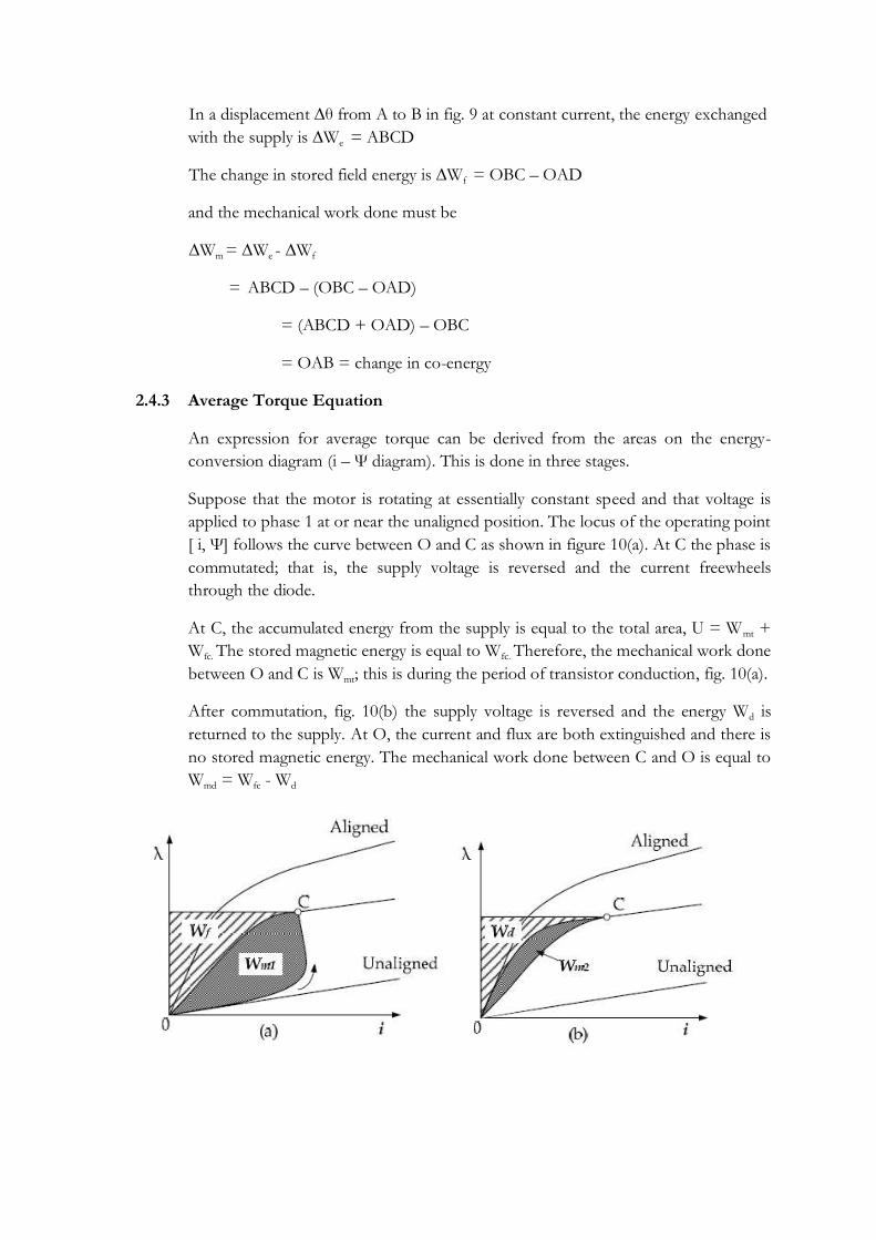
In a displacement ∆θ from A to B in fig. 9 at constant current, the energy exchanged
with the supply is ∆We = ABCD
The change in stored field energy is ∆Wf = OBC – OAD
and the mechanical work done must be
∆Wm = ∆We - ∆Wf
= ABCD – (OBC – OAD)
= (ABCD + OAD) – OBC
= OAB = change in co-energy
2.4.3 Average Torque Equation
An expression for average torque can be derived from the areas on the energy-
conversion diagram (i – Ψ diagram). This is done in three stages.
Suppose that the motor is rotating at essentially constant speed and that voltage is
applied to phase 1 at or near the unaligned position. The locus of the operating point
[ i, Ψ] follows the curve between O and C as shown in figure 10(a). At C the phase is
commutated; that is, the supply voltage is reversed and the current freewheels
through the diode.
At C, the accumulated energy from the supply is equal to the total area, U = Wmt +
Wfc. The stored magnetic energy is equal to Wfc. Therefore, the mechanical work done
between O and C is Wmt; this is during the period of transistor conduction, fig. 10(a).
After commutation, fig. 10(b) the supply voltage is reversed and the energy Wd is
returned to the supply. At O, the current and flux are both extinguished and there is
no stored magnetic energy. The mechanical work done between C and O is equal to
Wmd = Wfc - Wd

Fig.4: Average torque, energy-conversion loop
Total mechanical work done in 1 stroke, Wm = Wmt + Wmd
1 stroke means 1 fluxing period (transistor conduction period) and 1 defluxing
period (diode conduction period)
Energy returned to supply, R = Wd
Energy supplied by controller, U = Wmt + Wfc
= Wmt + Wmd + Wd
= Wm +R
The term energy ratio is used to characterize the availability of the original energy
for conversion.
Energy ratio, E = Wm/ (Wm+R) = Wm/U
The average torque can now be determined from the number of energy-
conversion loops per revolution, that is, the number of strokes per revolution. In
one revolution all Nr poles must be worked on by all m phases. The number of
strokes per revolution is mNr and therefore the average torque over one revolution
is
T = mNrWm/2π
2.5 DYNAMIC OPERATION OF SRM
For the effective operation of SRM, energization of motor phases w.r.t rotor
position is to be synchronized. For motoring operation to happen, the phase
winding should have current when the rotor poles are approaching the stator poles
i.e, during the time of rising inductance.
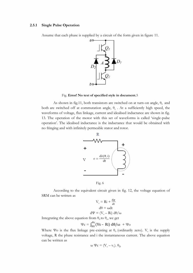
2.5.1 Single Pulse Operation
Assume that each phase is supplied by a circuit of the form given in figure 11.
Fig. Error! No text of specified style in document.5
As shown in fig.11, both transistors are switched on at turn-on angle, θ0 and
both are switched off at commutation angle, θc . At a sufficiently high speed, the
waveforms of voltage, flux linkage, current and idealised inductance are shown in fig.
13. The operation of the motor with this set of waveforms is called ‗single-pulse
operation‘. The idealised inductance is the inductance that would be obtained with
no fringing and with infinitely permeable stator and rotor.
Fig. 6
According to the equivalent circuit given in fig. 12, the voltage equation of
SRM can be written as
Vs = Ri + 𝑑𝜑
𝑑𝑡
dθ = ωdt
dΨ = (Vs – Ri) dθ/ω
Integrating the above equation from θ0 to θc, we get
Ψc = (Vs – Ri) dθ/ωθc
θ0 + Ψo
Where Ψo is the flux linkage pre-existing at θ0 (ordinarily zero). Vs is the supply
voltage, R the phase resistance and i the instantaneous current. The above equation
can be written as
ω Ψc = (Vs – v1). θD

where θD is the dwell angle and v1 is the mean volt-drop due to resistance during θD.
If Ri << Vs , the flux-linkage rises linearly.
Fig. 7: Waveforms of single pulse operation
In motoring operation, the flux should ideally be reduced to zero before the
poles are separating, otherwise the torque changes sign and becomes a braking
torque. To accomplish this the terminal voltage must be reversed at θc and is usually
done by the action of the freewheeling diodes when the transistors turn off. The
angle taken for the negative voltage to drive the flux back to zero at the extinction
angle θq is again governed by faraday‘s law:
0= Ψo + (−Vs – Ri) dθ/ωθq
θc
And this can be written as
ω Ψc = (Vs + v2). (θq – θc)
where v2 is the mean volt-drop due to resistance in the de-fluxing period θq – θc. If
Ri<<Vs the flux-linkage falls linearly, and at constant speed the angle traversed is

nearly equal to the dwell angle, both being equal to Ψc /Vs. The total conduction
angle covers the entire cycle of building and extinguishing the flux and is equal to
θq – θc = 2 ω Ψc /Vs
The peak flux-linkage Ψc occurs at the commutation angle θc.
In a regular switched reluctance motor, the angle of rising inductance is only
αp/2 where αp is the angle of rotation between two successive aligned positions.
Ideally the flux should be zero throughout the period of falling inductance, because
current flowing in that period produces a negative or braking torque. To avoid this
completely, the conduction angle must be restricted to αp/2 .
2.5.2 Chopping-Voltage PWM
Chopping is necessary to control the current at low speed. The simplest
scheme is to leave one transistor on during the period θ0 to θc, and to switch the
other one on and off at a high frequency with a fixed duty-cycle d = tON/T where
tON is the on-time and T is the period of the chopping frequency. This strategy is
called soft chopping.
Figure 14: Voltage PWM – soft chopping

When Q1 is on, voltage Vs is connected to the phase winding. When it is off, the
winding is short-circuited through Q2 and D2. Q1 is called the ―chopping transistor and D2
the ―chopping diode‖. Q2 is called the ‗commutating transistor‘ and D1 the commutating
diode, because they change state only at the commutation angles θ0 and θc .
The waveforms during soft chopping are shown in Fig. 14. During the dwell angle
the average voltage applied to the phase winding is dVs. Again using the parameter р to
represent the averaged effect of resistive volt-drops, the flux-linkage rise in the dwell period
can be equated to the flux-linkage fall in the de-fluxing period to give
This can be rearranged to show that the total conduction angle is
To prevent continuous conduction, θD must be restricted to
In hard chopping, both transistors are switched together at high frequency. Soft
chopping produces lower acoustic noise and less EMI. It also decreases the DC ripple
current in the supply and substantially reduces the requirement for filter capacitance.
In both soft and hard chopping, the flux-linkage waveform increases in regular steps
with more-or –less constant average slope. Before the start of overlap, the average slope of
the current waveform is also nearly constant as the linearly increasing flux is forced into a
constant inductance (Ψ = Li). Thereafter, the inductance increases more or less linearly
while the flux-linkage continues to rise linearly. Consequently, the current tends to become
constant. Unlike the single pulse waveform, the current waveform under voltage PWM does
not hit the overlapping pole corners with a high current and there is evidence that it
produces quieter operation. Not only is the current lower at the start of overlap, but also
there are repeated short freewheeling periods which may help to soften the mechanical
impact.
2.5.3 Chopping - current regulation
Fig. 15 shows the waveforms obtained with a hysteresis type current regulator in which the
power transistors are switched off or on according as the current is greater or less than a
reference current. The instantaneous phase current is measured using a wide-bandwidth
current transducer, and fed back to a summing junction. The error is used directly to control
the states of the power transistors. As in the case of voltage-PWM, soft chopping decreases
the current ripple and the filter requirements.
The simple hysteresis controller maintains the current waveform between an upper
and a lower limit - in the hysteresis band. As the supply voltage is fixed, the result is that the
switching frequency decreases as the incremental inductance of the phase winding increases.
(The incremental inductance increases along with the total inductance.) This can be seen in
Fig. 15.

In Fig. 15 the flux-linkage waveform shows a period of constant flux linkage before
the start of overlap, as constant current is being forced into a constant inductance.
Thereafter, the inductance increases while the average current remains constant, so the flux-
linkage rises along with the inductance.
Fig. 15: Current regulation – soft chopping
2.6 POWER ELECTRONIC CONTROLLERS
The direction of the torque does not depend on the signs or values of flux-linkage
and current, but only on the sign of dL/dθ, the rate of change of inductance with rotor
position. The advantage is that the flux linkage and current can be unipolar i.e. not
alternating and hence incur lower iron losses and permit simpler form of controller.
The controller must therefore, supply precisely phased unipolar current pulses
relative to the rotor position. It must regulate the magnitude and even the waveshape of the
current, to fulfil the requirements of torque and speed control to ensure safe operation of
the motor and the power transistors. It must also be capable of applying pulses of reverse
voltage for de-fluxing which is effected by freewheeling diodes.
The most convenient power source is a battery or rectified AC supply. The ripple
current tends to be large with an irregular waveshape rich in harmonics. So it is essential to
provide sufficient filter capacitance at the supply terminals.
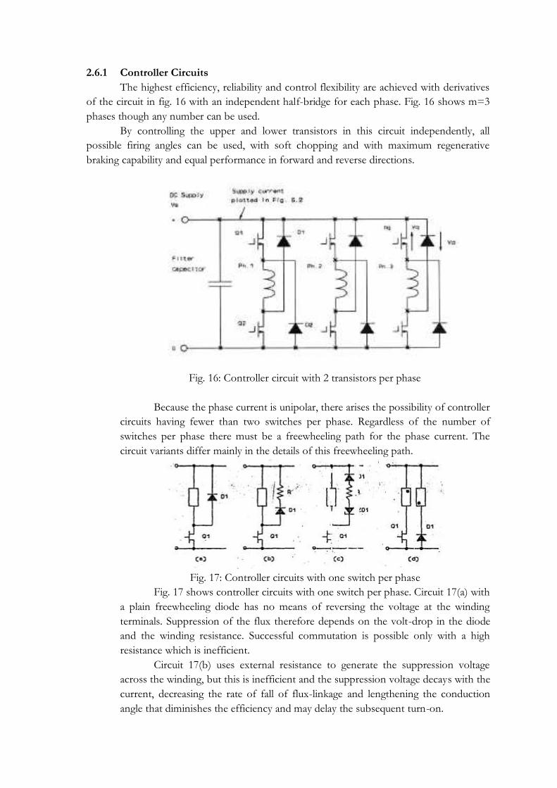
2.6.1 Controller Circuits
The highest efficiency, reliability and control flexibility are achieved with derivatives
of the circuit in fig. 16 with an independent half-bridge for each phase. Fig. 16 shows m=3
phases though any number can be used.
By controlling the upper and lower transistors in this circuit independently, all
possible firing angles can be used, with soft chopping and with maximum regenerative
braking capability and equal performance in forward and reverse directions.
Fig. 16: Controller circuit with 2 transistors per phase
Because the phase current is unipolar, there arises the possibility of controller
circuits having fewer than two switches per phase. Regardless of the number of
switches per phase there must be a freewheeling path for the phase current. The
circuit variants differ mainly in the details of this freewheeling path.
Fig. 17: Controller circuits with one switch per phase
Fig. 17 shows controller circuits with one switch per phase. Circuit 17(a) with
a plain freewheeling diode has no means of reversing the voltage at the winding
terminals. Suppression of the flux therefore depends on the volt-drop in the diode
and the winding resistance. Successful commutation is possible only with a high
resistance which is inefficient.
Circuit 17(b) uses external resistance to generate the suppression voltage
across the winding, but this is inefficient and the suppression voltage decays with the
current, decreasing the rate of fall of flux-linkage and lengthening the conduction
angle that diminishes the efficiency and may delay the subsequent turn-on.

Circuit 17(c) uses a zener diode to sustain a higher value of suppression
voltage during the freewheeling period.
Circuit 17(d) uses a bifilar wound motor. When the transistors turns off, the
current transfers to the secondary and freewheels through the diode. The circuit
permits full voltage reversal but does not permit soft chopping because there is no
zero-volt condition. The peak voltage on the transistor is twice the supply voltage,
plus an additional transient voltage due to the imperfect coupling between the
primary and secondary. This may be large enough to necessitate the use of a
snubber, destroying the simplicity of the circuit and decreasing the efficiency; which
is already seriously compromised by the use of a bifilar winding.
Fig. 18 shows the Oulton controller circuit. It has the advantage of full
reverse voltage for flux suppression. The DC link voltage is split with capacitors. A
disadvantage is that, soft chopping is not possible, and balance must be carefully
maintained between the phases, but the circuit successfully achieves the minimum of
one transistor per phase without adding extraneous passive components or
sacrificing control flexibility or efficiency.
Fig. 18: Oulton type SR control circuit
2.6.2 Controller circuits with shared components
Fig. 19: (n+1) switch circuit

Fig 19 shows a three-phase controller circuit with four transistors The upper
transistor Q serves all three phases, while the lower transistors commutate the phases. Q
must be operated with a sufficiently low duty-cycle so that when one phase is turning off it
has sufficient reverse voltage. This circuit can be used with two or four phases also. A useful
variant uses one upper between each pair of phases in a 4-phase drive, giving a total of 6
transistors as shown in Fig. 20. If the chopping transistors are connected to phases 1 & 3
and 2 & 4 respectively, the problem of overlap is greatly reduced and all phases can have the
maximum reverse voltage during turn-off.
Fig. 20: 2(n+1) switch circuit
The chopping transistor Q is working all the time, whereas the commutating
transistors have a duty-cycle of only one-third. Consequently the switching and conduction
losses as well as the mean and RMS currents in the chopping transistor are higher than in
the conmutating transistors. The use of a common chopping transistor also destroys the
―fault tolerance‖ of the circuit in Fig. 19, because the phases are no longer, as independent
of one another.
Instead of sharing the supply transistors, the freewheeling circuit can be shared, as in
Fig. 21, the C-dump circuit. All three phases freewheel into the dump capacitor Cd. The
charge (and voltage) builds up on Cd and is typically controlled to an average value of about
2Vs by a step-down chopper consisting of Q, Ld, and D. The circuit operates like a large
snubber with energy recovery to the supply. The recirculating energy is generally a large
fraction of the total throughput and therefore the chopper components and the dump
capacitor are not small. Moreover, failure in the dump circuit is liable to permit the durnp
capacitor to charge up uncontrollably with catastrophic results.
Fig. 21: C-dump circuit

2.6.3. Generator Circuits
The switched reluctance machine is capable of operating continuously as a generator.
This is possible with those of the circuits reviewed above which can connect reverse to the
phase winding through freewheeling diodes. It must also be possible for the supply circuit to
be capable of absorbing or diverting the returned power.
The switched reluctance machine can be caused to regenerate by retarding the firing
angles so that the bulk of the winding conduction period comes after the aligned position,
when dL/dθ < 0.
In such cases excitation power is first supplied from the DC source while the
transistors are conducting (i.e, during the dwell period from θ0 to θc), and generating power
is returned to the DC source during the de-fluxing or suppression period (from θc to θq).
For generator to be sustained, the energy returned during the de-fluxing period must exceed
the excitation energy supplied during the dwell period. The difference between the electrical
input energy and the electrical output energy is provided by the prime mover.
It is possible to separate the excitation circuit from the output circuit by means of a
connection such as Fig. 22. This will be recognized as the circuit of the boost (or up)
converter.
Fig. 22: SR generator circuit based on boost converter
The only fundamental difference is that the inductance is not constant but varies
with rotor position in such a way that mechanical work is added to the stored field energy
during the conduction angle, so that the output power exceeds the excitation power. The
output voltage in Fig. 22 must exceed the input voltage. This leads to a problem at low
speed & the reverse voltage across the phase winding extinguishes the flux too quickly, and
the energy-conversion loop is cut off with only a fraction of its maximum possible area.
Fig. 23: SR generator circuit based on buck converter

The circuit of Fig. 23 alleviates this problem. It is based on the buck (or down)
converter. The output voltage is less than the supply voltage. At a given speed the
suppression angle θq - θc is expanded approximately in the ratio Vo/Vs compared with the
dwell angle θc - θo. Consequently a much fuller energy-conversion loop is obtained.
2.7 CONTROL OF SRM
Fig. 24 shows the block diagram of the switched reluctance motor connected to a
load with closed-loop speed control. The controller structure is similar to that of AC and
DC drives. The switched reluctance motor can be considered as a ―black box whose input is
current and whose output is torque. Ofcourse the current includes the currents of all phases,
and it is understood that the current waveshape as well as its magnitude must be controlled
to some extent because the waveshape is not pure DC or pure AC and indeed it varies with
both speed and load. It may be necessary in some applications to control the waveshape of
the current in a precise predetermined manner to minimize torque ripple.
The controller can be regarded as a black box whose input is the speed error and
whose output is the motor current. The speed error is the difference between the reference
(desired) speed and the actual (feedback) speed, which is derived from a speed transducer
that is coupled to the load or the motor. Fig. 24 conveys only a basic example of closed loop
speed control. Similar diagrams can be put together for a torque controller or a generator
controller.
Fig. 24: Control system architecture
For motoring operation the pulses of phase current must coincide with a period of
increasing inductance, i.e. a pair of rotor poles is approaching alignment with the stator poles
of the excited phase. The timing and dwell of the current pulse determine the torque, the
efficiency and other parameters. In d.c. and brushless d.c. motors the torque per ampere is
more or less constant. But in the SR motor no such simple relationship emerges naturally.
With fixed firing angles, there is a monotonic relationship between average torque and r.m.s.
phase current, but in general it is not very linear. This may present some complications in
feedback-controlled systems although it does not prevent the SR motor from achieving
‗near-servo quality‘ dynamic performance, particularly in respect of speed range,
torque/inertia, and reversing capability. Because the characteristics of the SR drive are
essentially controlled by the phasing of switching instants relative to the rotor position,
digital control is not only very natural but can be implemented extremely effectively with
flexibility or ‗programmability‘ of the characteristics and with reliable, repeatable results.

Fig. 25: Schematic of current-regulator for one phase. (a) Hysteresis-type. (b) Voltage-p.w.m.
type (duty-cycle control)
At low speeds the self-e.m.f. of the winding is small and the current must be limited
by chopping or p.w.m. of the applied voltage. The regulating strategy employed has a
marked effect on the performance and the operating characteristics. A hysteresis-type
current-regulator maintains a more or less constant current throughout the conduction
period in each phase. Figure 25(a) shows schematically the method of control. As the
current reference increases, the torque increases. At low currents the torque is roughly
proportional to current squared, but at higher currents it becomes more nearly linear. At
very high currents, saturation decreases the torque per ampere again. This type of control
produces a constant-torque type of characteristic as indicated in Fig. 26. With loads whose
torque increases monotonically with speed, such as fans and blowers, speed adjustment is
possible without tachometer feedback, but in general, feedback is needed to provide can be
accurate speed control. In some cases the pulse train from the shaft position sensor may be
used for speed feedback, but only at relatively high speeds. At low speeds a larger number of
pulses per revolution is necessary and this can be generated by an optical encoder or
resolver, or alternatively by phase-locking a high-frequency oscillator to the pulses of the
commutation sensor. Systems with resolver- feedback or high-resolution optical encoders
can work right down to zero speed. The ‗hysteresis-type‘ current, regulator may require
current transducers of wide bandwidth, but the SR drive has the advantage that they
grounded at one end, with the other connected to the negative terminal of the lower phase
leg switch. Shunts or Hall-effect sensors can be used, or alternatively, ‗Sensefets‘ with in-
built current sensing. Much of the published literature on SR drives describes this form of
control.
Figure 25(b) shows an alternative regulator using fixed-frequency p.w.m. of the
voltage with variable duty-cycle. After commutation the current decays through the diodes
somewhat more rapidly because the reverse voltage applied is effectively 1/d times the
forward voltage applied before commutation (d= duty cycle). The duty-cycle (or off-time‘)
of the p.w.m. can be varied by a simple monostable circuit. This form of control is similar to
armature- voltage control in a d.c. motor.
Current feedback can be added to the circuit of Fig. 25(b) to provide a signal which
when subtracted from the voltage reference, modulates the duty cycle of the p.w.m and
compounds the torque speed characteristic It is possible in this way to achieve under-
compounding, over-compounding, or flat compounding just as in a d.c. motor with a wound

field. For many applications the speed regulation obtained by this simple scheme will be
adequate. For precision speed control, normal speed feedback can be added. The current
feedback can also be used for thermal overcurrent sensing.
Fig.26: Constant-torque characteristic obtained with regulator of Fig. 25(a).
A desirable feature of both the hysteresis-type current-regulator and the voltage
p.w.m. regulator is that the current waveform tends to retain much the same shape over a
wide speed range.
When the p.w.m. duty cycle reaches 100 per cent the motor speed can be increased
by increasing the dwell (the conduction period), the advance of the current-pulse relative to
the rotor position or both. These increases eventually reach maximum practical values, after
which the torque becomes inversely proportional to speed squared, but they can typically
double the speed range at constant torque.
2.8 TORQUE-SPEED CHARACTERISTICS
Fig. 27: General torque/speed characteristic of switched reluctance motor.
The generic form of the torque/speed capability curve is shown in Fig. 27. For
speeds below ωb the torque is limited by the motor current (or the controller current,

whichever is less). Up to the ‗base speed‘ ωb, it is possible, by means of the regulators in Fig.
25, to get any value of current into the motor, up to the maximum. The precise value of
current at a given operating point depends on the load characteristics, the speed, and the
regulator and control strategy.
In the speed range below ωb the firing angles can be chosen to optimize efficiency or
minimize torque ripple. If the load never needs to operate at high speeds above ωb, it will
usually be possible to design the pole geometry to optimize these parameters without regard
to the efficiency at high speeds, and this provides considerable design freedom to obtain
smooth torque and simplify the control.
The ‗corner point‘ or base speed ωb is the highest speed at which maximum current
can be supplied at rated voltage, with fixed firing angles. If these angles are still kept fixed,
the maximum torque at rated voltage decreases with speed squared. However, if the
conduction angle is increased (mainly by advancing the turn-on angle) there is a considerable
speed range over which maximum current can still be forced into the motor and this
sustains the torque at a level high enough to maintain a constant-power characteristic even
though the core losses and windage losses increase quite rapidly with speed. This is shown in
Fig. 27 between points B and P. The angle θD is the ‗dwell‘ or conduction angle of the main
switching device in each phase. It should generally be possible to maintain constant power
up to 2-3 times base speed.
The increase in conduction angle may be limited by the need to avoid continuous
conduction, which occurs when the conduction angle exceeds half the rotor pole -pitch. It
may be limited to lower values by the core loss or other factors. At P the increase in θD is
halted and higher speeds can now only be achieved with the natural characteristic, i.e. torque
decreasing with speed squared.
At very low speeds the torque/speed capability curve may deviate from the flat-
torque characteristic. If the chopping frequency is limited (as with GTO, thyristors, for
example), or if the bandwidth of the current regulator is limited, it may be difficult to limit
the peak current without the help of the self-e.m.f. of the motor, and the current reference
may have to be reduced. This is shown in curve (i) in Fig. 26. On the other hand, if this is
not a problem, the very low windage and core losses may permit the copper losses to be
increased, so that, with higher current a higher torque is obtained, as shown in curve (ii).
Under intermittent conditions, of course, very much higher torques can be obtained in any
part of the speed range up to base speed.
It is important to note that the current which limits the torque below base speed is
the motor current (or converter output current). The d.c. supply current increases from a
small value near zero speed to a maximum value at base speed. Basically this is because the
power increases in proportion to the speed as long as the torque is constant. With fixed d.c.
supply voltage at the input to the converter, the d.c. supply current is then proportional to
the speed. If the torque is less than maximum, of course the d.c. supply current is also
smaller.

MODULE – III

3. SYNCHRONOUS RELUCTANCE MOTOR
3.1 CONSTRUCTION OF SYNCHRONOUS RELUCTANCE MOTOR
The idealized structure of reluctance motor is same as that of the salient pole
synchronous machine except that the rotor does not have any field winding. The stator has a
three phase symmetrical winding, which creates sinusoidal rotating magnetic field in the
airgap and the reluctance torque is developed because the induced magnetic field in the rotor
has a tendency to cause the rotor to align with the stator field at a minimum reluctance
position.
Fig 3.1: Idealized three phase two pole synchronous machine (Salient pole)
The rotor of the modern reluctance machine is designed with iron laminations in the
axial direction separated by nonmagnetic material as shown in fig. 3.2, to increase the
reluctance to flux in the q axis. Compared to the induction motor, it is slightly heavier and
has a lower power factor. With proper design, the performance of the reluctance motor may
approach that of induction machine. With a high saliency ratio (Lds/Lqs), a power factor of
0.8 can be reached. The efficiency of a reluctance machine may be higher than an induction
motor because there is no rotor copper loss. Because of inherent simplicity, robustness of
construction and low cost, reluctance machines have been popularly used in many low
power applications such as fiber spinning mills, where a number of motors operate
synchronously with a common power supply.
The synchronous reluctance motor has no synchronous starting torque and runs up
from stand still by induction action. There is an auxiliary starting winding. Subsequent design
modifications involved the introduction of a segmental rotor construction and flux barrier in
each pole. This has increased the pull out torque, the power factor and the efficiency.

Fig 3.2: Cross-section of synchronous reluctance motor
Synchronous reluctance motor can broadly be classified into
(a) Axially laminated and
(b) Radially laminated synchronous motors.
These motors have the same stator construction as the multiphase induction motor.
Generally three types of rotors are used in synchronous reluctance motor. They are
segmental, flux barrier (radially laminated) and axially laminated structure.
The ideal synchronous reluctance machine is having a rotor whose structure is such
that the inductance of the stator windings in the dq reference - frame varies sinusoidally
from a maximum value Ld (direct inductance) to a minimum value Lq (quadrature
inductance) as a function of angular displacement of the rotor.
3.1.1 ROTOR DESIGN
Salient rotor (Segmental):
Salient rotor shape is such that the quadrature air-gap is much larger than the direct
air gap. This yields reactively small Ld/Lq ratios in the range of 2.3. Salient rotor design is
shown in fig. 3.3.

Fig 3.3: Salient rotor
Radially Laminated Rotor (Flux barrier):
Fig. 3.4: Radially laminated Rotor
Another approach is to use laminations with ―flux barriers‖ punched into the steel
for a 4 pole machine as shown in fig. 3.4. However these flux barriers and the central hole of
the lamination required for the shaft weaken the rotor structurally and thus makes this
approach a poor choice for high speed design.
Axially laminated rotor:
The fig. 6.6 shows the axially laminated rotor.
Fig 3.5: Axially laminated rotor
This approach is to laminate the rotor in the axial direction. For a two pole two
phase axially laminated rotor with an Ld/Lq ratio of 20, a maximum efficiency of 94% has
been reported. It is observed that torque ripple and iron losses are more in axially laminated
rotor than radially laminated rotor.
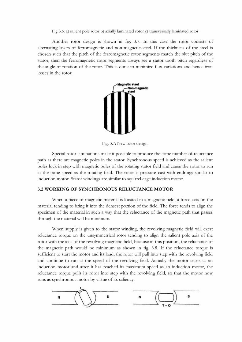
Fig 3.6: a) salient pole rotor b) axially laminated rotor c) transversally laminated rotor
Another rotor design is shown in fig. 3.7. In this case the rotor consists of
alternating layers of ferromagnetic and non-magnetic steel. If the thickness of the steel is
chosen such that the pitch of the ferromagnetic rotor segments match the slot pitch of the
stator, then the ferromagnetic rotor segments always see a stator tooth pitch regardless of
the angle of rotation of the rotor. This is done to minimize flux variations and hence iron
losses in the rotor.
Fig. 3.7: New rotor design.
Special rotor laminations make it possible to produce the same number of reluctance
path as there are magnetic poles in the stator. Synchronous speed is achieved as the salient
poles lock in step with magnetic poles of the rotating stator field and cause the rotor to run
at the same speed as the rotating field. The rotor is pressure cast with endrings similar to
induction motor. Stator windings are similar to squirrel cage induction motor.
3.2 WORKING OF SYNCHRONOUS RELUCTANCE MOTOR
When a piece of magnetic material is located in a magnetic field, a force acts on the
material tending to bring it into the densest portion of the field. The force tends to align the
specimen of the material in such a way that the reluctance of the magnetic path that passes
through the material will be minimum.
When supply is given to the stator winding, the revolving magnetic field will exert
reluctance torque on the unsymmetrical rotor tending to align the salient pole axis of the
rotor with the axis of the revolving magnetic field, because in this position, the reluctance of
the magnetic path would be minimum as shown in fig. 3.8. If the reluctance torque is
sufficient to start the motor and its load, the rotor will pull into step with the revolving field
and continue to run at the speed of the revolving field. Actually the motor starts as an
induction motor and after it has reached its maximum speed as an induction motor, the
reluctance torque pulls its rotor into step with the revolving field, so that the motor now
runs as synchronous motor by virtue of its saliency.

Fig. 3.8: Rotor positions due to revolving magnetic field
Reluctance motors have approximately one-third the HP rating they would have as
induction motors with cylindrical rotors. Although the ratio may be increased to one-half by
proper design of the field windings, power factor and efficiency are poorer than for the
equivalent induction motor. Reluctance motors are subject to ―cogging‖ since, the locked
rotor torque varies with the rotor position, but the effect may be minimized by skewing the
rotor bars and by not having the number of rotor slots exactly equal to an exact multiple of
the number of poles.
3.3 PHASOR DIAGRAM
Fig. 3.9: Phasor diagram of synchronous reluctance motor.
Phasor diagram of synchronous reluctance motor is shown in fig. 3.9 where Ф is the
phase angle, ν is the load angle, Xd & Xq are direct and quadrature axis reactances, Id & Iq
are direct and quadrature axis current and Vs is the supply voltage.
In the phasor diagram, the stator resistance is neglected. Thus,
Vs = jIdXd +jIqXq
3.4 RELUCTANCE TORQUE EQUATION
The equivalent circuit of a salient pole synchronous machine is shown in fig. 3.10.
The only difference of synchronous reluctance motor with salient synchronous machine is
that it does not have any rotor winding.
In the equivalent circuit, Vs is the supply voltage, Is, the stator current, Vf is the speed emf
or excitation emf and Ls the inductance of stator winding which includes magnetizing
inductance Lm and leakage inductance Lls

Fig. 3.10: Equivalent circuit of salient synchronous machine
Fig. 3.11: Phasor diagram of salient pole synchronous motor
From the phasor diagram of salient pole synchronous machine shown in Fig. 3.11, we can
write
Iscosø = Iqs cosδ - Ids sinδ ..............................................................................................(1)
The input power Pi can be given as
Pi = 3Vs Iscosø .........................................................................................................(2)
Substituting eqn. (1) in eqn. (2)
Pi = 3Vs (Iqs cosδ - Ids sinδ) ...................................................................................(3)
Again, from the phasor diagram we can write
Ids = (Vs cosδ – Vf)/Xds .......................................................................................(4)
and Iqs = Vs sinδ / Xqs ......................................................................................................(5)
Substituting equations (4) and (5) in (3),

𝑃𝑖 = 3𝑉𝑠 (𝑉𝑠 sin δ
Xqs 𝑐𝑜𝑠δ −
Vs cos δ – Vf
Xdssinδ)
= 3𝑉𝑠𝑉𝑓
𝑋𝑑𝑠𝑠𝑖𝑛δ + 3Vs2sinδcosδ
1
Xqs−
1
Xds
=3𝑉𝑠𝑉𝑓
𝑋𝑑𝑠𝑠𝑖𝑛δ + 3Vs2sin2δ
Xds −Xqs
2XdsXqs ..........................................................................(6)
If the losses are neglected, then Pi = Te * ωm
= Te * ωe *2/P
Substituting for Pi from equation (6), we write
Te = 3𝑃
2
1
𝜔𝑒 𝑉𝑠𝑉𝑓
𝑋𝑑𝑠𝑠𝑖𝑛δ + Vs2sin2δ
Xds −Xqs
2XdsXqs
For a synchronous reluctance motor, only reluctance torque component will be present.
Therefore, by putting Vf = 0 in the above torque equation of salient synchronous machine,
we can obtain the reluctance torque equation for synchronous reluctance motor.
Te = 3𝑃
2
1
𝜔𝑒Vs2sin2δ
Xds −Xqs
2XdsXqs
The torque – δ angle characterisitics of salient pole synchronous motor is shown in fig 3.12.
For a synchronous reluctance motor, only the reluctance torque component is there. The
steady state stability limit corresponds to the maximum point. Here, the stability limit is
reached at δ = ±π/4.
Fig. 3.12: Torque – load angle characteristics of salient pole machine.

3.5 TORQUE - SPEED CHARACTERISTICS:
The torque speed characteristics of synchronous reluctance motor is shown in fig.
3.13. The motor starts at anywhere from 300 to 400 percent of its full load torque
(depending on the rotor position of the unsymmetrical rotor with respect to the field
winding) as a two phase motor. As a result of the magnetic rotating field created by a
starting and running winding displaced 900 in both space and time.
At about 3/4th of the synchronous speed a centrifugal switch opens the starting
winding and the motor continues to develop a single phase torque produced by its running
winding only. As it approaches synchronous speed, the reluctance torque (developed as a
synchronous motor) is sufficient to pull the rotor into synchronism with the pulsating single
phase field. The motor operates at constant speed upto a little over 200% of its full load
torque. If it is loaded beyond the value of pull out torque, it will continue to operate as a
single phase induction motor upto 500% of its rated output.
Fig. 3.13: Torque - Speed characteristics.
3.6. APPLICATIONS:
Synchronous reluctance motors can be used when several motors must operate in
synchronism for co-ordering machine where a wide range of highly regulated speed control
is required with variable frequency drive.
1. It is widely used for many constant speed applications such as recording instruments, time
devices. Control apparatus, regulators and phonograph turntables.
2. Proportioning devices on pumps or conveyors.
3. Synthetic fibre manufacturing equipment.
4. Wrapping and folding machines.

5. Processing continuous sheet or film material.
6. Auxiliary time mechanism.
7. Synchronized conveyors.
8. Metering pumps.
Application characteristics:
* Comparable power density but better efficiency than induction motor.
* Slightly lower power factor than induction motor.
* Slightly small field weakening range than induction motor.
* High cost than induction motor but lower than any type of PM motors.
* Need speed synchronisation to inverter out frequency by rotor position sensor and
sensorless control.
* Sensorless control is much easier due to motor saliency.
* By adding squirrel cage induction motor to synchronous reluctance motor one obtains line
starting reluctance motors.
* Line started reluctance motors can be parallel with open loop control if the load does not
change suddenly
* Other combinations are possible such as adding PM for improved performance.
* Rotor design for best manufacturability is still being optimised especially for high speed
applications.
ADVANTAGES OVER PM MACHINES:
There is no concern with demagnetization, hence synchronous reluctance machines
are inherently more reliable than PM machines.
There need not be any excitation field as torque is zero, thus eliminating
electromagnetic spinning losses.
Synchronous reluctance machine rotors can be constructed entirely from high-
strength, low cost materials.

MODULE – IV

4. BRUSHLESS PERMANENT MAGNET DC MOTOR
4.1 COMMUTATION IN DC MOTORS The hetropolar magnetic field in the airgap of a dc machine induces an alternating
emf in the armature conductors. This emf is available across brushes as unidirectional emf
because of commutator and brushes arrangement. The dc current passing through the
brushes is so distributed in the armature winding (because of commutator and brushes
arrangement) that unidirectional torque is developed in armature conductor. A dc current
passing through the brushes because of commutator and brushes action, always sets up a
mmf whose axis is in quadrature with the main field axis, irrespective of the speed of the
armature.
4.1.1 Mechanical commutator:
Commutator is made up of specially shaped commutator segments made up of
copper as shown in fig. 4.1.
Fig. 4.1: Commutator segment
These segments are separated by thin mica sheets of similar shape. The commutator
segments are tapered such that when assembled they form a cylinder. These segments are
mechanically fixed to the shaft using V-shaped circular steel clamps, but are isolated
electrically from the shaft using suitable insulation between the clamps and the segment as
shown in fig. 4.2.

Fig. 4.2: Connection of commutator segments to shaft
The schematic representation of a mechanical commutator and brushes arrangement
is shown in the fig. 4.3. It represents a case with 2 brushes and 12 commutator segments.To
start with the brush X contacts with CS1 and brush Y with 7. A dc supply is connected
across the brushes X and Y. The dc current passes through brush X, CS1, tapping 1, tapping
7 and brush Y. There are two armature parallel paths between tappings 1 and 7. The current
passing through the armature winding sets up a magnetomotive force whose axis is along the
axes of tappings 7 and 1 of the brush axes Y and X.
Fig 4.3. Mechanical commutator and brushes arrangement
Allow the armature to rotate by an angle in a counter clockwise direction. Then the
brush X contacts CS2 and the tapping 2 and the brush Y. Contact CS8 and tapping 8. The
dc. current passes through the tappings 2 and 8 there are two parallel paths
(i) 2—3—4—5—6—7—8
(ii) 2—1—12—11—10—9—8
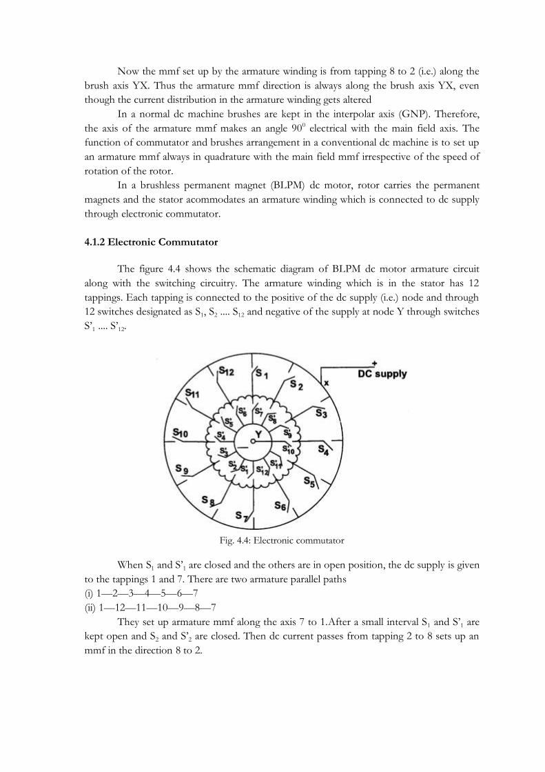
Now the mmf set up by the armature winding is from tapping 8 to 2 (i.e.) along the
brush axis YX. Thus the armature mmf direction is always along the brush axis YX, even
though the current distribution in the armature winding gets altered
In a normal dc machine brushes are kept in the interpolar axis (GNP). Therefore,
the axis of the armature mmf makes an angle 900 electrical with the main field axis. The
function of commutator and brushes arrangement in a conventional dc machine is to set up
an armature mmf always in quadrature with the main field mmf irrespective of the speed of
rotation of the rotor.
In a brushless permanent magnet (BLPM) dc motor, rotor carries the permanent
magnets and the stator acommodates an armature winding which is connected to dc supply
through electronic commutator.
4.1.2 Electronic Commutator
The figure 4.4 shows the schematic diagram of BLPM dc motor armature circuit
along with the switching circuitry. The armature winding which is in the stator has 12
tappings. Each tapping is connected to the positive of the dc supply (i.e.) node and through
12 switches designated as S1, S2 .... S12 and negative of the supply at node Y through switches
S‘1 .... S‘12.
Fig. 4.4: Electronic commutator
When S1 and S‘1 are closed and the others are in open position, the dc supply is given
to the tappings 1 and 7. There are two armature parallel paths
(i) 1—2—3—4—5—6—7
(ii) 1—12—11—10—9—8—7
They set up armature mmf along the axis 7 to 1.After a small interval S1 and S‘1 are
kept open and S2 and S‘2 are closed. Then dc current passes from tapping 2 to 8 sets up an
mmf in the direction 8 to 2.

Fig. 4.5: Switching circuit of electronic commutator
Thus by operating the switches in a sequential manner it is possible to get a
revolving mmf in the air gap. The switching circuit is redrawn as shown in fig. 4.5. The
switches S1 to S12 and S‘1 to S‘12 can be replaced by power electronic switching devices such
as SCRs, MOSFETs, IGBTs, power transistors etc. When SCRs are used, suitable
commutating circuit should be included. Depending upon the type of forced commutation
employed, each switch requires one or two SCRs and other commutating devices. As
number of devices is increased, the circuit becomes cumbersome.
For normal electronic commutator, usually six switching devices are employed. Then
the winding should have three tappings. Therefore the winding can be connected either in
star or in delta.
Fig. 4.6: Delta - connected stator armature winding

Fig. 4.7: Star - connected armature winding.
The above circuits as shown in fig. 4.6 and 4.7 are the same as that of a 3-phase
bridge inverter, but here the switching of the devices is influenced by rotor position sensor.
4.1.3. Comparison between mechanical commutator and electronic commutator:
Mechanical commutator and brushes
Electronic commutator
Commutator is made up of copper segments and mica insulation. Brushes are of carbon or graphite.
Power electronic switching device are used in the commutator. It requires a position sensor.
Commutator arrangement is located in the rotor.
It is located in the stator.
Shaft position sensing is inherent in the arrangement.
Separate rotor position sensor is required.
Number of commutator segments are very high.
Number of switching devices is limited to 6.
There exists sliding contact between commutator and brushes. Sparking takes place. Requires regular maintenance.
No sliding contact. No sparking as it is possible to feedback the stored energy in the magnetic field to the mains. Requires less maintenance.
Difficult to control the voltage available across the tappings.
The voltage available across armature tappings can be controlled by employing PWM techniques.
Highly reliable
Reliability is improved by specially designing the devices and protective circuits
Interpole windings are employed to have sparkless commutation.
By suitably operating the switching devices, better performance can be achieved.
4.2 SQUARE WAVE PM BRUSHLESS MOTOR DRIVES (BLDC MOTORS) The brushless D.C. motor is shown in its most usual form in Figure 4.8 alongside
the PM D.C. commutator motor. The stator structure is similar to that of polyphase a.c.
induction motor. The function of the magnet is the same in both the brushless motor and
the D.C. commutator motor. In both cases the air gap flux is ideally fixed by the magnet and
little affected by armature current.

FIG. 4.8. (a) Brushless D.C. motor and (b) PM D.C. commutator motor.
The most obvious advantage of the brushless configuration is the removal of the
brushes. Brush maintenance is no longer required, and many problems associated with
brushes are eliminated. For example, brushes tend to produce RFI (radio-frequency
interference) and the sparking associated with them is a potential source of ignition in
inflammable atmospheres. RFI at least has the advantage of high frequency, so that filter
components need not be very large. This is not necessarily the case with the lower-order
harmonics associated with the commutation of the brushless motor. Commutator motors
are quite commonly immersed in automobile petrol tanks to drive the fuel pump. This
shows that they are not automatically excluded from 'hazardous' environments.
The problems that arise with commutator motors are sometimes not so obvious. In
some applications the accumulation of brush debris or dust is a problem, particularly if it
gets into the bearings or if it forms a conducting track that leads to flashover. The operation
and life of brushes depend on factors such as atmospheric conditions, which may necessitate
the use of different brush grades in the same motor operating in different climates.
An advantage of the brushless configuration in which the rotor is inside the stator is
that more cross-sectional area is available for the power or 'armature' winding. At the same
time the conduction of heat through the frame is improved. Generally an increase in the
electric loading is possible, providing a greater specific torque. The efficiency is likely to be
higher than that of a commutator motor of equal size, and the absence of brush friction
helps further in this regard.
The absence of commutator and brush gear reduces the motor length. This is useful
not only as a simple space saving, but also as a reduction in the length between bearings, so
that for a given stack length the lateral stiffness of the rotor is greater, permitting higher
speeds or a longer active length/diameter ratio. This is important in servo-type drives where
a high torque/inertia ratio is required.The removal of the commutator reduces the inertia
still further.
The brushless configuration does not come without some disadvantages. The two
main disadvantages relative to the commutator motor are
(i) The need for shaft position sensing and
(ii) Increased complexity in the electronic controller.

Also, the brushless motor is not necessarily less expensive to manufacture than the
commutator motor, which is perhaps slightly more amenable to automated manufacture.
4.3 CONSTRUCTION OF BLDC
STATOR
The stator of a BLDC motor consists of stacked steel laminations with windings
placed in the slots that are axially cut along the inner periphery. Traditionally, the stator
resembles that of an induction motor; however, the windings are distributed in a different
manner. Most BLDC motors have three stator windings connected in star fashion. Each of
these windings is constructed with numerous coils interconnected to form a winding. One
or more coils are placed in the slots and they are interconnected to make a winding. Each of
these windings is distributed over the stator periphery to form an even numbers of poles.
There are two types of stator windings variants: trapezoidal and sinusoidal motors.
This differentiation is made on the basis of the interconnection of coils in the stator
windings to give the different types of back Electromotive Force (EMF). As their names
indicate, the trapezoidal motor gives a back EMF in trapezoidal fashion and the sinusoidal
motor‘s back EMF is sinusoidal. In addition to the back EMF, the phase current also has
trapezoidal and sinusoidal variations in the respective types of motor. This makes the torque
output by a sinusoidal motor smoother than that of a trapezoidal motor. However, this
comes with an extra cost, as the sinusoidal motors take extra winding interconnections
because of the coils distribution on the stator periphery, thereby increasing the copper intake
by the stator windings.
ROTOR
The rotor is made of permanent magnet and can vary from two to eight pole pairs
with alternate North (N) and South (S) poles. Based on the required magnetic field density
in the rotor, the proper magnetic material is chosen to make the rotor. Ferrite magnets are
traditionally used to make permanent magnets. As the technology advances, rare earth alloy
magnets are gaining popularity. The ferrite
magnets are less expensive but they have the disadvantage of low flux density for a given
volume. In contrast, the alloy material has high magnetic density per volume and enables the
rotor to compress further for the same torque. Also, these alloy magnets improve the size-
to-weight ratio and give higher torque for the same size motor using ferrite magnets.
Neodymium (Nd), Samarium Cobalt (SmCo) and the alloy of Neodymium, Ferrite and
Boron (NdFeB) are some examples of rare earth alloy magnets.Continuous research is going
on to improve the flux density to compress the rotor further. Figure 4.9 shows cross
sections of different arrangements of magnets in a rotor.

Fig 4.9: Cross-section of different rotor types
4.4 PRINCIPLE OF OPERATION
The brushless DC motor differs from the normal DC motor in that it employs
electrical commutation of the armature current rather than the mechanical commutation.
The word brushless is used to define the combination of motor, its electronic drive circuit
and rotor position sensor. The electronic drive is an inverter which consists of IGBT‘s,
which feeds stator windings. The IGBT‘s are controlled by pulses generated by rotor
position sensors. This ensures that rotor revolves at angular speed which is equal to the
average speed of the field produced by the stator.
Like a DC motor the driver circuit is fed from a DC supply. The stator and rotor
fields remains stationary with respect to each other at all the speeds. The torque speed
characteristic is similar to a DC motor. The speed can be controlled by controlling the input
dc voltage. Because of these similarities and as it does not have brushes, it is known as
brushless DC motor.
4.5 HALL SENSORS
Unlike a brushed DC motor, the commutation of a BLDC motor is controlled
electronically. To rotate the BLDC motor, the stator windings should be energized in a
sequence. It is important to know the rotor position in order to understand which winding
will be energized following the energizing sequence. Rotor position is sensed using Hall
effect sensors embedded into the stator. Most BLDC motors have three Hall sensors
embedded into the stator on the non-driving end of the motor. Whenever the rotor
magnetic poles pass near the Hall sensors, they give a high or low signal, indicating the N or
S pole is passing near
the sensors. Based on the combination of these three Hall sensor signals, the exact sequence
of commutation can be determined.

Fig 4.10: Transverse section of BLDC motor
Fig. 4.11: Cross-sectional view of BLDC motor
Figure 4.10 shows a transverse section of a BLDC motor with a rotor that has alternate N
and S permanent magnets and Figure 4.11 shows its cross sectional view. Hall sensors are
embedded into the stationary part of the motor. Embedding the Hall sensors into the stator
is a complex process because any misalignment in these Hall sensors, with respect to the
rotor magnets, will generate an error in determination of the rotor position. To simplify the
process of mounting the Hall sensors onto the stator, some motors may have the Hall
sensor magnets on the rotor, in addition to the main rotor magnets. These are a scaled down
replica version of the rotor. Therefore, whenever the rotor rotates, the Hall sensor magnets
give the same effect as the main magnets. The Hall sensors are normally mounted on a PC
board and fixed to the enclosure cap on the non-driving end. This enables users to adjust
the complete assembly of Hall sensors, to align with the rotor magnets, in order to achieve
the best performance. Based on the physical position of the Hall sensors, there are two
versions of output. The Hall sensors may be at 60° or 120° phase shift to each other. Based
on this, the motor manufacturer defines the commutation sequence, which should be
followed when controlling the motor.
4.6 OPTICAL SENSORS
The optical sensor has a light source, three photo transistors P1, P2 and P3 mounted
on the end plate of the motor, separated by 120 degree from each other and a revolving
shutter coupled to the shaft of the motor. The optical sensor is shown in the figure 4.12.

Fig 4.12: Arrangement of an optical sensor
The stator consists of a three pole stator winding and a two pole rotor consisting of
permanent magnets. The driving circuit consists of three transistors Q1, Q2 and Q3 used to
excite the stator windings. The arrangement is shown in figure 4.12.
Fig. 4.12: Schematic arrangement of unipolar brushless dc motor
When the shutter revolves, the phototransistor gets exposed to the light in the
sequence of their numbers. In each revolution, the phototransistors generate the pulses Pl1,
Pl2 and Pl3 which have duration and displacement of 120 degrees. This is shown in figure
4.13.

Fig. 4.13: Pulses generated by phototransistors
When light falls on the photo transistors P1, it generates a pulse and transistors Q1
gets turned on. Hence current starts flowing through stator winding Ph1. This produces
North Pole at pole face of Ph1. Due to this South Pole gets attracted towards it and reaches
the axis of pole face of Ph1. Hence rotor revolves in anticlockwise direction. During this
mean time, the light stops falling on P1 and starts falling of P2. Hence Pulse Pl2 is generated
which turns on the transistor Q2. So current now starts flowing through stator winding Ph2,
producing North Pole. Hence rotor further rotates in anticlockwise direction. So the rotor
reaches the axis of the pole face of Ph2. In the mean time the light stops falling on P2 and
starts falling on P3. This causes transistor Q3 to turn on which produces North Pole at the
pole face of Ph3. This rotates the rotor further in anticlockwise direction. Switching
sequence repeats and continuous rotation of rotor is obtained.
The torque reversal cannot be obtained just by reversing the DC supply as in the
case of a conventional DC motor. It can be achieved by operating the timing and base drive
circuit in such a way that the transistors Q1, Q2 and Q3 conduct for the duration of the
pulses Pl2, Pl3 and Pl1 respectively. The torque reversal can also achieved by shifting the
base drive signals of the transistors by 180 degrees. This circuit does not use any feed back
or freewheeling diodes. This is satisfactory for small motors. In small motors, the inductive
energy in the phase windings is very small, to cause any destruction to the transistors.
The cost of this motor is low and drive circuit is simple. The main limitation of this
motor is that it cannot be used for power levels above 100 watts. In large power levels, the
stored energy in the phase winding inductance is large and hence feedback diodes are
necessary, in such cases bipolar brushless dc motors are used.
4.7 MULTI PHASE BRUSHLESS MOTORS
BLPM motors are classified on the basis of number of phase windings and the
number of pulses given to the devices during each cycle.

1. One phase winding and one pulse BLPM motor:
The stator has one phase winding as shown in fig. 4.14. It is connected to the supply
through a power semiconductor switch. When the rotor position sensor is influenced by say
N-pole flux, the stator operates and the rotor developes a torque. When the RPS is under
the influence of S-pole, the transistor is in off state. The rotor gets torque whenever the
rotor position is under the influence of N-pole.
Fig. 4.14: One phase one pulse BLPM motor.
The current and torque are approximated as sinusoidally varying as shown in fig.
4.15
.
Fig. 4.15: Current and torque waveform
Advantages:
1. One transistor and one position sensor is sufficient.
2. Inertia should be such that the rotor rotates continuously.
3. Utilisation of transistor and winding are less than 50%.
2. One phase two pulse BLPM motor:
Stator has only one winding. It is connected to DC three wire supply through two
serniconductor devices as shown in fig. 4.16.

Fig. 4.16: One phase two pulse BLPM motor
There is only one position sensor. When the position sensor is under the N-pole
influence, T1 is in on-state and T2 is in off-state. When it is under the influence of S-pole,
T2 is on and T1 is off.
Fig. 4.17: Torque waveform
In the first case, when T1 is on, the winding carries current from A to B and when
T2 is on, the winding carries current from B to A. The polarity of the flux setup by the
winding gets altered depending upon the position of the rotor. This provides unidirectional
torque as shown in fig. 4.17.
Advantages:
* Winding utilization is better.
* Torque developed is more uniform.
Demerit:
* Transistor utilization is less
* The current needs a 3-wire dc supply.
3. Two phase winding and two pulse BLPM motor:
Stator has two phase windings which are displaced by 180° electrical. Electrical
connections are as shown in fig. 4.18. It makes use of two semiconductor switches.

Fig. 4.18: Two phase winding and two pulse motor
Fig. 4.19: Torque waveform
Performance of this type is similar to one phase 2 pulse BLPM motor. Torque
waveform are as shown in fig. 4.19. However it requires two independent phase windings.
Merit:
* Better torque waveform
Demerit:
* Their utilization is only 50% which is less.
* Cabling with rotor position sensor should be made proper.
4. Three phase winding and three pulse BLPM motor:
The stator has 3 phase windings as shown in fig. 4.20 which are displaced by 1200
elec. apart. Each phase windings is controlled by a semiconductor switch which is operated
depending upon the position of the rotor. Three position sensors are required for this
purpose.
Fig. 4.20: 3 phase, 3 pulse BLPM motor.
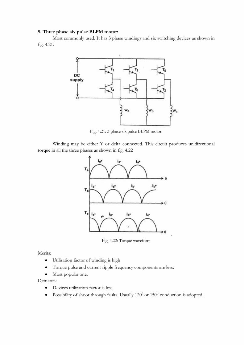
5. Three phase six pulse BLPM motor:
Most commonly used. It has 3 phase windings and six switching devices as shown in
fig. 4.21.
Fig. 4.21: 3-phase six pulse BLPM motor.
Winding may be either Y or delta connected. This circuit produces unidirectional
torque in all the three phases as shown in fig. 4.22
.
Fig. 4.22: Torque waveform
Merits:
Utilisation factor of winding is high
Torque pulse and current ripple frequency components are less.
Most popular one.
Demerits:
Devices utilization factor is less.
Possibility of shoot through faults. Usually 1200 or 150° conduction is adopted.

4.8 TORQUE AND EMF EQUATION
The basic torque and e.m.f. equations of the brushless D.C. motor are quite simple,
and resemble those of the D.C. commutator motor. A simple 'concept machine' is shown in
Fig. 4.23(a). Note that the two-pole magnet has a pole arc of 180 degrees. The air gap flux-
density waveform is ideally a square wave as shown in Fig. 4.23(b). In practice, fringing
causes the corners to be somewhat rounded. The coordinate axes have been chosen so that
the centre of a north pole of the magnet is aligned with the x-axis, i.e. at θ = 0.
The stator has 12 slots and a three-phase winding. Thus there are two slots per pole
per phase. Each phase winding consists of two adjacent full-pitch coils of N1 turns each,
whose axes are displaced from one another by 30 degrees. The winding is a single-layer
winding, and any slot contains N1 conductors from only one phase winding. This winding is
equivalent, in the active length, to a degenerate concentric winding with only one coil per
pole per phase, having a fractional pitch of 5/6.
Fig 4.23(a)
Consider the flux-linkage Ψ1 of coil a1A1 as the rotor rotates. This is shown in Fig.
4.23(c). Note that θ now represent the movement of the rotor from the reference position in
Fig. 4.23(a). The flux linkage varies linearly with rotor position because the air gap flux-
density set up by the magnet is constant over each pole-pitch of the rotor. Maximum
positive flux-linkage occurs at θ = 00 and maximum negative flux linkage at θ = 180°.
By integrating the flux-density around the air gap, the maximum flux-linkage of the
coil can be found as
𝛹1𝑚𝑎𝑥 = 𝑁1 𝐵 𝜃 𝑟𝑑 𝜃𝑙 = 𝑁1𝐵𝑔𝜋𝑟𝑙
Or
Flux linked by the coil at the position θ = 00 is given by
∅𝑚𝑎𝑥 = 𝐵𝑔2𝜋𝑟
𝑃𝑙 = flux/pole
where Bg be the flux density in the airgap in wb/m2 , r be the radius of airgap in metre, l be
the length of armature in metre and p be the number of poles.
Therefore, 𝛹1𝑚𝑎𝑥 = 𝑁1∅𝑚𝑎𝑥 = 𝑁1𝐵𝑔2𝜋𝑟
𝑃𝑙
Here, P=2

So, 𝛹1𝑚𝑎𝑥 = 𝑁1𝐵𝑔𝜋𝑟𝑙
The variation of θ as the rotor rotates from 0 to 1800 is given by
𝛹1 θ = 1 −θ
𝜋2 𝛹1𝑚𝑎𝑥
The emf induced in coil a1A1 is given by
𝑒1 = −𝑑𝛹1
𝑑𝑡= −
𝑑𝛹1
𝑑θ 𝑑θ
𝑑t= −𝜔
𝑑𝛹1
𝑑θ= −𝜔
2
𝜋𝑁1𝐵𝑔𝑟𝜋𝑙
= 2𝑁1𝐵𝑔𝑟𝑙 𝜔 𝑣𝑜𝑙𝑡𝑠 ; 𝜔 = mechanical angular velocity in
rad/sec.
In Fig. 4.23(d), note that the waveform of e.m.f. in this full-pitch coil with respect
to time is an exact replica of the flux-density waveform with respect to position around the
rotor in Fig. 4.23(b). The e.m.f. induced in the second coil of phase A is identical, but
retarded in phase by 30°. This is shown in Fig. 4.23(e). If the two coils are connected in
series, the total phase voltage is the sum of the two separate coil voltages, and this is shown
in Fig. 4.23(f). The basic effect of distributing the winding into two coils is to produce a
stepped e.m.f. waveform. In practice, fringing causes its corners to be rounded, as shown by
the dotted lines. The waveform then has the 'trapezoidal' shape that is characteristic of the
brushless D.C. motor. With 180° magnet arcs and two slots per pole per phase, the flat top
of this waveform is ideally 150° wide, but in practice the fringing field reduces this to a
somewhat smaller value,
possibly as little as 120°.

Fig 4.23
The magnitude of the flat-topped phase e.m.f. is given by
e1 = 2Nph Bg lr ω Volts
where Nph is the number of turns in series per phase. In this case Nph = 2N1, because the
two coils considered are assumed to be in series. In a machine with p pole-pairs, the
equation remains valid provided Nph is the number of turns in series per phase and ω is in
mechanical radians per second.
Figure 4.23(g) shows an ideal rectangular waveform of phase current, in which the
current pulses are 120 electrical degrees wide and of magnitude I. The positive direction of
current is against the e.m.f., that is, positive current is motoring current. The conduction
periods of the three phases are symmetrically phased so as to produce a three-phase set of
balanced 120° square waves. If the phase windings are star-connected, as in Fig. 4.24(a), then
at any time there are just two phases and two transistors conducting. During any 120°
interval of phase current the instantaneous power being converted from electrical to
mechanical is
P = ω Te = 2eI
The '2' in this equation arises from the fact that two phases are conducting.

Fig 4.24: Converter or Inverter of BLDC motor (a) With star connected Phase Winding (b) With
Delta Connected Phase Winding
Using the expression derived above for the e.m.f., the electromagnetic torque is
given by
Te = 4Nph Bg lr I Nm
This equation is valid for any number of pole-pairs. The similarity between the
brushless motor and the commutator motor can now be seen. Writing E=2e to represent
the combined e.m.f. of two phases in series, the e.m.f. and torques equations can be written
in the form
E = KΦω and T = KΦI
where K = 4Nph/π and Φ = Bg π r l
K is the 'armature constant' and Φ is the flux. These equations for e.m.f. and torque are
exactly the same as for the D.C. commutator motor; only the form of the constant K is
different. It is clear that with ideal wave shapes and with perfect commutation, these
equations are true at all instants of time. The electronic commutation of the converter
switches has thus assumed the function of the mechanical commutator in the commutator
motor, to give a pure 'd.c.' machine with constant, ripple-free torque.
4.9 TORQUE – SPEED CHARACTERISTICS
The torque/speed curve of the ideal brushless motor can be derived from the
foregoing equations.
If the commutation is perfect and the current waveforms are exactly as shown in Fig.
4.24(g), and if the converter is supplied from an ideal direct voltage source V, then at any
instant the following equation can be written for the D.C. terminal voltage:
V = E + RI
where R is the sum of two phase resistances in series and E is the sum of two phase
e.m.f.s in series. This equation is exactly the same as that of the commutator motor. The
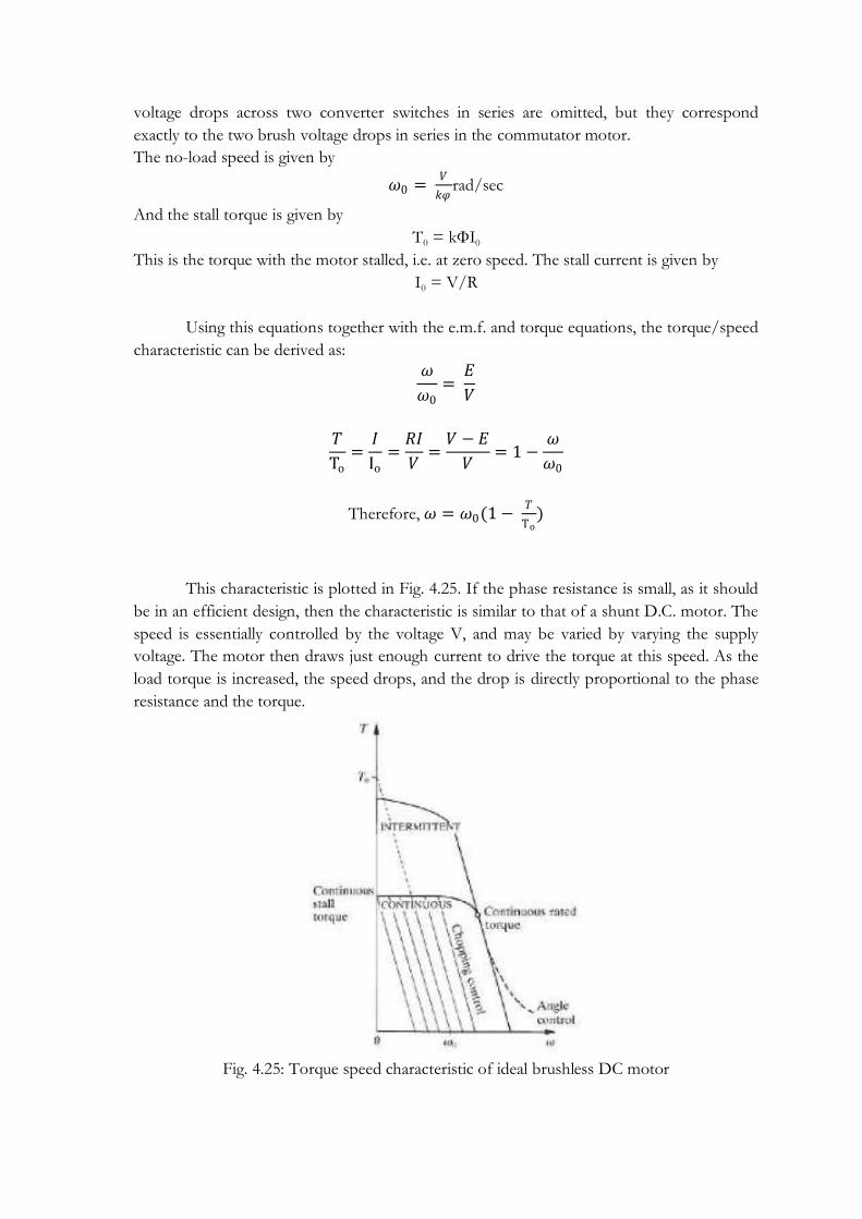
voltage drops across two converter switches in series are omitted, but they correspond
exactly to the two brush voltage drops in series in the commutator motor.
The no-load speed is given by
𝜔0 = 𝑉
𝑘𝜑rad/sec
And the stall torque is given by
T0 = kФI0
This is the torque with the motor stalled, i.e. at zero speed. The stall current is given by
I0 = V/R
Using this equations together with the e.m.f. and torque equations, the torque/speed
characteristic can be derived as:
𝜔
𝜔0=
𝐸
𝑉
𝑇
To=
𝐼
Io=
𝑅𝐼
𝑉=
𝑉 − 𝐸
𝑉= 1 −
𝜔
𝜔0
Therefore, 𝜔 = 𝜔0(1 − 𝑇
To)
This characteristic is plotted in Fig. 4.25. If the phase resistance is small, as it should
be in an efficient design, then the characteristic is similar to that of a shunt D.C. motor. The
speed is essentially controlled by the voltage V, and may be varied by varying the supply
voltage. The motor then draws just enough current to drive the torque at this speed. As the
load torque is increased, the speed drops, and the drop is directly proportional to the phase
resistance and the torque.
Fig. 4.25: Torque speed characteristic of ideal brushless DC motor
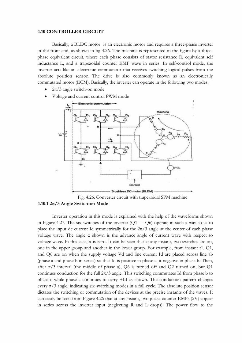
4.10 CONTROLLER CIRCUIT
Basically, a BLDC motor is an electronic motor and requires a three-phase inverter
in the front end, as shown in fig 4.26. The machine is represented in the figure by a three-
phase equivalent circuit, where each phase consists of stator resistance R, equivalent self
inductance L, and a trapezoidal counter EMF wave in series. In self-control mode, the
inverter acts like an electronic commutator that receives switching logical pulses from the
absolute position sensor. The drive is also commonly known as an electronically
commutated motor (ECM). Basically, the inverter can operate in the following two modes:
2π/3 angle switch-on mode
Voltage and current control PWM mode
Fig. 4.26: Converter circuit with trapezoidal SPM machine
4.10.1 2π/3 Angle Switch-on Mode
Inverter operation in this mode is explained with the help of the waveforms shown
in Figure 4.27. The six switches of the inverter (Q1 — Q6) operate in such a way so as to
place the input dc current Id symmetrically for the 2π/3 angle at the center of each phase
voltage wave. The angle α shown is the advance angle of current wave with respect to
voltage wave. In this case, α is zero. It can be seen that at any instant, two switches are on,
one in the upper group and another in the lower group. For example, from instant t1, Q1,
and Q6 are on when the supply voltage Vd and line current Id are placed across line ab
(phase a and phase b in series) so that Id is positive in phase a, it negative in phase b. Then,
after π/3 interval (the middle of phase a), Q6 is turned off and Q2 turned on, but Q1
continues conduction for the full 2π/3 angle. This switching commutates Id from phase b to
phase c while phase a continues to carry +Id as shown. The conduction pattern changes
every π/3 angle, indicating six switching modes in a full cycle. The absolute position sensor
dictates the switching or commutation of the devices at the precise instants of the waves. It
can easily be seen from Figure 4.26 that at any instant, two phase counter EMFs (2V) appear
in series across the inverter input (neglecting R and L drops). The power flow to the

machine at any instant is ideally constant and is given by P = 2 V Id which is indicated at the
bottom of fig 4.27. The inverter is basically operating as a rotor position-sensitive electronic
commutator. Therefore, although it is an ac drive with inverter and synchronous motor, dc
machine-like behavior makes it popularly known as a brushless dc motor (BLDM) Note
that instead of a constant voltage source Vd, the supply can be a variable voltage or current
source.
Fig 4.27: Stator phase voltages and current waves indicating the converter conducting
devices
4.10.2 PWM Voltage and Current Control Mode
In the previous discussion the inverter switches were controlled to give
commutation function only when the devices were sequentially on for 2π/3-angle duration.
In addition to commutator function, it is possible to control the switches in PWM chopping
mode for controlling voltage and current continuously at the machine terminal. Figure 4.28
shows the waveforms with chopping mode, current-controlled operation of the inverter.
There are essentially two chopping modes: feedback (FB) mode and freewheeling (FW)
mode. In these modes, the devices are turned on and off on a duty cycle basis to control the
machine average current Iav and the corresponding average voltage Vav. Consider, for
example, the FB mode,
for the π/3 interval from instant t1 when Q1 and Q6 are chopping together. When Q1Q6
are on, phase a and phase b currents will increase (Vd>2Vc). However, when the devices are
turned off, the current will decrease because of feedback through diodes D3D4, and the
average machine terminal voltage V will be determined by the duty ratio. The average phase

voltage is given by Vav = Vc + IavRs. A single dc link current sensor will sense the average
machine current because machine current is always flowing in the line
In FW mode, chopping control is done with only one device. For example in Figure
4.28 all the upper devices (Q1, Q3, and Q5) are kept on sequentially in the middle of the
respective positive voltage half cycles. In the π/3 interval following t1, device Q6 is
chopping. When Q6 on, Vd is applied across ab and the current increases. When Q6 is
turned off, decaying freewheeling current (due to counter EMF) flows through Q1 and D3,
short-circuiting the motor tenninals. In figure 4.28 six step current waves are shown with
rise and fall times at the leading and trail edges, respectively, because in the practical case,
commutation takes a finite amount of time.
Fig. 4.28: Waveforms with PWM current control mode operation of inverter
The PWM mode is useful for starting a BLDM for the 2π/3 angle switch-on mode
with initial current limit control. In this mode, the machine is gradually brought to full speed
current-limited starting, and then transferred to the 2π/3 switch-on mode. This is like the
starting operation of a conventional dc motor. This mode also permits continuous speed
control of BLDM.
4.10.3 Controller circuit
The general structure of a controller for a brushless PM motor is shown in Fig. 4.29.
This schematic diagram shows the functions required to control the drive in the 'chopping
control' range of Fig. 4.25, i.e., the commutation angles are fixed. The rotor shaft position is
sensed by a Hall-effect sensor, a slotted optical disk, or some other transducer. These signals
are 'decoded' by combinational logic to provide the firing signals for 120° conduction on

each of the three phases. The commutation logic or 'rotor position decoder' therefore has
six outputs which control the upper and lower phasel eg transistors. Programmable logic
arrays, gate arrays, and EPROMS are all suitable for this function. In general there will be
level-shifting circuits to buffer the outputs of the logic circuit and provide the drive to the
power devices.
The basic forward control loop is a voltage control, implemented in Fig. 4.29 by a
mono stable clocked at a fixed reference frequency, which is typically a few kHz. In general
it is desirable to make this frequency ultrasonic to minimize noise. The duty-cycle or off-
time is controlled by an analogue voltage reference that represents the desired speed. In Fig.
4.29 the p.w.m. is applied only to the lower phase leg transistors. This not only reduces the
current ripple but also avoids the need for wide bandwidth in the level-shifting circuit that
feeds the upper phase leg transistors. With higher D.C. supply voltages this can be a useful
saving. The upper transistors need not be of the same type as the lower ones and need only
switch at the commutation frequency, i.e. only a few hundred Hz. Note the use of AND
gates as a simple
way of combining the commutation and chopping signals to the lower transistors.
From a control point of view the brushless motor is similar to the D.C. commutator
motor, as the simple torque and voltage equations show. Consequently it is possible to
implement current (torque) feedback and speed feedback in the same way as for the d.c.
motor, and generally this results in a well-behaved system although compensation may be
necessary in either or both loops to improve stability and transient response. A tight speed
control is thus possible over a wide range of speed and torque using relatively simple
techniques that are familiar with commutator motors. This is in contrast, to some degree,
with the a.c. induction motor, which cannot accommodate speed and torque control loops
in this form without having reference-frame transformations, as in the field-oriented control
technique, or their equivalent.
Sometimes the instantaneous current in the brushless PM motor is regulated in each
phase by a hysteresis-type regulator which maintains the current within adjustable limits.
This is called 'current-mode' control and several algorithms are possible to control the
switching. In this case current sensors are needed in each phase, and their bandwidth must
obviously be considerably wider than that of the sensing resistor shown in Fig. 4.29. The
speed feedback signal, derived in Fig. 4.29 from a tachometer-generator TG, can also be
derived from the shaft position sensor by a frequency-to-voltage converter. This technique
only works at high speeds.
Many of the functions of the circuit in Fig. 4.29 can be performed digitally, and it is
increasingly common to have a serial communications interface that permits the system to
be computer controlled. In high-performance systems the shaft position sensor may be a
resolver or optical encoder, with special purpose decoding circuitry. At this level of control
sophistication, it is possible to fine-tune the firing angles and the p.w.m. control as a
function of speed and load, to improve various aspects of performance such as efficiency,
dynamic performance, or speed range.

Fig. 4.29: Structure of controllers for PMBLDC motors

MODULE – V
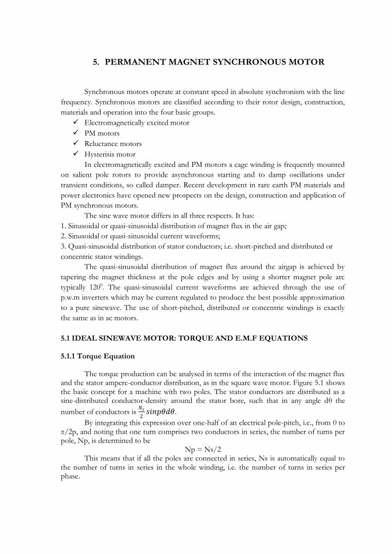
5. PERMANENT MAGNET SYNCHRONOUS MOTOR
Synchronous motors operate at constant speed in absolute synchronism with the line
frequency. Synchronous motors are classified according to their rotor design, construction,
materials and operation into the four basic groups.
Electromagnetically excited motor
PM motors
Reluctance motors
Hysterisis motor
In electromagnetically excited and PM motors a cage winding is frequently mounted
on salient pole rotors to provide asynchronous starting and to damp oscillations under
transient conditions, so called damper. Recent development in rare earth PM materials and
power electronics have opened new prospects on the design, construction and application of
PM synchronous motors.
The sine wave motor differs in all three respects. It has:
1. Sinusoidal or quasi-sinusoidal distribution of magnet flux in the air gap;
2. Sinusoidal or quasi-sinusoidal current waveforms;
3. Quasi-sinusoidal distribution of stator conductors; i.e. short-pitched and distributed or
concentric stator windings.
The quasi-sinusoidal distribution of magnet flux around the airgap is achieved by
tapering the magnet thickness at the pole edges and by using a shorter magnet pole arc
typically 1200. The quasi-sinusoidal current waveforms are achieved through the use of
p.w.m inverters which may be current regulated to produce the best possible approximation
to a pure sinewave. The use of short-pitched, distributed or concentric windings is exactly
the same as in ac motors.
5.1 IDEAL SINEWAVE MOTOR: TORQUE AND E.M.F EQUATIONS 5.1.1 Torque Equation The torque production can be analysed in terms of the interaction of the magnet flux and the stator ampere-conductor distribution, as in the square wave motor. Figure 5.1 shows the basic concept for a machine with two poles. The stator conductors are distributed as a sine-distributed conductor-density around the stator bore, such that in any angle dθ the
number of conductors is 𝑁𝑠
2𝑠𝑖𝑛𝑝𝜃𝑑𝜃.
By integrating this expression over one-half of an electrical pole-pitch, i.e., from 0 to π/2p, and noting that one turn comprises two conductors in series, the number of turns per pole, Np, is determined to be
Np = Ns/2 This means that if all the poles are connected in series, Ns is automatically equal to the number of turns in series in the whole winding, i.e. the number of turns in series per phase.

Fig. 5.1. (a) Ideal sine wave brushless motor with pure sine-distributed phase winding and permanent-magnet rotor with sine-distributed flux, (b) turns/pole for two-pole winding, (c) turns/pole for four-pole winding.
In the following analysis the angle θ is in mechanical degrees or radians. The stator ampere conductor distribution is a sine-distributed current sheet of the same form as the conductor distribution, such that in angle dθ the ampere-conductors flowing in the positive direction (out of the paper) are
i 𝑁𝑠
2𝑠𝑖𝑛𝑝𝜃𝑑𝜃
The rotor magnet flux distribution is centered on its north d-axis, which is displaced by a positive angle α from the axis of the stator winding:
B(θ) = 𝐵 cos(pθ −α) Here α is expressed in electrical radians. The force on the elementary group of ampere-conductors is in the circumferential direction and is
F= Bli 𝑁𝑠
2𝑠𝑖𝑛𝑝𝜃cos(pθ −α ) 𝑑𝜃
Together with the corresponding force on the opposite element, this force produces a couple 2Fr1 on the stator. An equal and opposite couple acts on the rotor and the total electromagnetic torque on the rotor is the integral of the elementary contributions over the whole airgap periphery: over p pole-pairs
𝑇 = −𝑝 2𝐹𝑟1
𝜋𝑝
0
𝑑𝜃
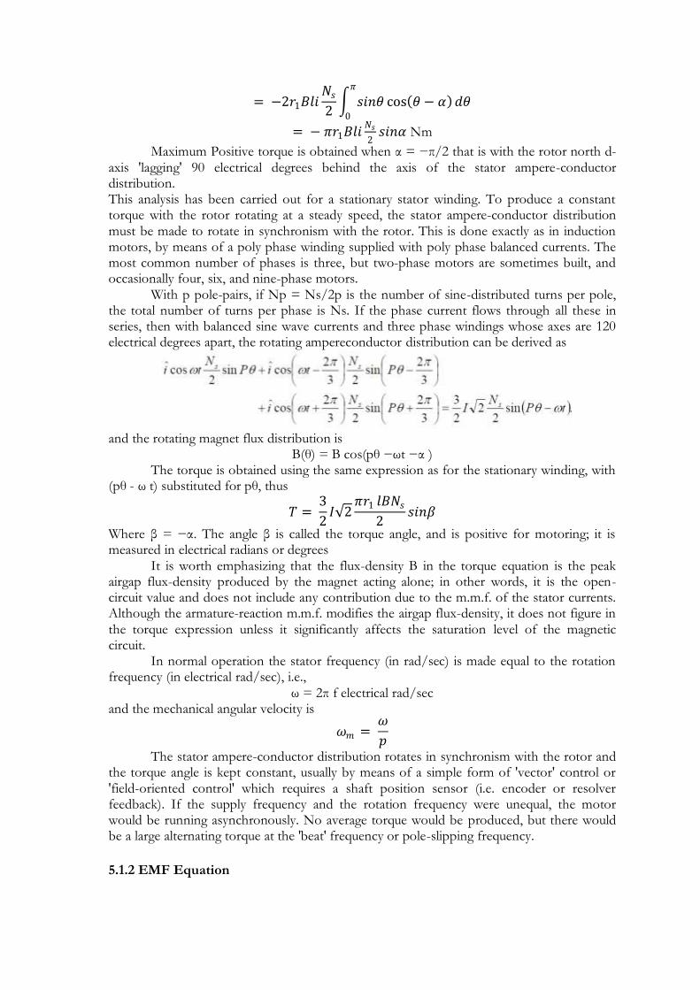
= −2𝑟1𝐵𝑙𝑖𝑁𝑠
2 𝑠𝑖𝑛𝜃 cos 𝜃 − 𝛼 𝑑𝜃
𝜋
0
= − 𝜋𝑟1𝐵𝑙𝑖𝑁𝑠
2𝑠𝑖𝑛𝛼 Nm
Maximum Positive torque is obtained when α = −π/2 that is with the rotor north d-axis 'lagging' 90 electrical degrees behind the axis of the stator ampere-conductor distribution. This analysis has been carried out for a stationary stator winding. To produce a constant torque with the rotor rotating at a steady speed, the stator ampere-conductor distribution must be made to rotate in synchronism with the rotor. This is done exactly as in induction motors, by means of a poly phase winding supplied with poly phase balanced currents. The most common number of phases is three, but two-phase motors are sometimes built, and occasionally four, six, and nine-phase motors. With p pole-pairs, if Np = Ns/2p is the number of sine-distributed turns per pole, the total number of turns per phase is Ns. If the phase current flows through all these in series, then with balanced sine wave currents and three phase windings whose axes are 120 electrical degrees apart, the rotating ampereconductor distribution can be derived as
and the rotating magnet flux distribution is
B(θ) = B cos(pθ −ωt −α ) The torque is obtained using the same expression as for the stationary winding, with (pθ - ω t) substituted for pθ, thus
𝑇 = 3
2𝐼 2
𝜋𝑟1 𝑙𝐵𝑁𝑠
2𝑠𝑖𝑛𝛽
Where β = −α. The angle β is called the torque angle, and is positive for motoring; it is measured in electrical radians or degrees It is worth emphasizing that the flux-density B in the torque equation is the peak airgap flux-density produced by the magnet acting alone; in other words, it is the open-circuit value and does not include any contribution due to the m.m.f. of the stator currents. Although the armature-reaction m.m.f. modifies the airgap flux-density, it does not figure in the torque expression unless it significantly affects the saturation level of the magnetic circuit. In normal operation the stator frequency (in rad/sec) is made equal to the rotation frequency (in electrical rad/sec), i.e.,
ω = 2π f electrical rad/sec and the mechanical angular velocity is
𝜔𝑚 = 𝜔
𝑝
The stator ampere-conductor distribution rotates in synchronism with the rotor and the torque angle is kept constant, usually by means of a simple form of 'vector' control or 'field-oriented control' which requires a shaft position sensor (i.e. encoder or resolver feedback). If the supply frequency and the rotation frequency were unequal, the motor would be running asynchronously. No average torque would be produced, but there would be a large alternating torque at the 'beat' frequency or pole-slipping frequency.
5.1.2 EMF Equation

The e.m.f. equation of the sine wave motor can be derived by considering the e.m.f.
induced in the elementary group of conductors in Fig. 5.1. Noting that Fig. 5.1 is drawn for
a two-pole machine (p = l), for a machine with p pole-pairs in series this e.m.f. is
𝑑𝑒 = 𝐵 𝜃 𝑙𝜔𝑚𝑟1
𝑁𝑠
2𝑠𝑖𝑛𝑝𝜃𝑑𝜃
But,
B(θ) = B cos(pθ −ωt −α )
and by integrating the contributions of all the elementary groups of conductors we get the
instantaneous phase e.m.f.:
𝑒 = 2𝑝 𝑑𝑒
𝜋𝑝
0
= 𝐵𝑙𝜔𝑟1𝑁𝑠𝜋
2𝑝sin(𝜔𝑡 + 𝛼)
The R.M.S. phase e.m.f. is therefore
𝐸𝑝 = 𝜋
2 2 𝐵𝑙𝜔𝑟1𝑁𝑠
𝑝𝑉𝑟𝑚𝑠
and the line-line e.m.f. is E 3
It is worth emphasizing again that the flux-density B is the peak airgap flux-density
produced by the magnet acting alone; in other words, it is the open-circuit value and does
not include any contribution due to the m.m.f. of the stator currents.
5.1.3 Equation for Power Developed in PMSM
The torque equation of PMSM is given by
𝑇 = 3
2𝐼 2
𝜋𝑟1 𝑙𝐵𝑁𝑠
2𝑠𝑖𝑛𝛽
And the phase emf is given by
𝐸𝑝 = 𝜋
2 2 𝐵𝑙𝜔𝑟1𝑁𝑠
𝑝𝑉𝑟𝑚𝑠
Combining the above two equations, we can write
𝑇 = 3𝑝𝐼𝐸𝑝
𝜔𝑠𝑖𝑛𝛽
The mechanical angular velocity is
𝜔𝑚 = 𝜔
𝑝
Therefore,
𝑇 = 3𝐼𝐸𝑝
𝜔𝑚𝑠𝑖𝑛𝛽
i.e, 𝑇. 𝜔𝑚 = 3𝐼𝐸𝑝 𝑠𝑖𝑛𝛽
Power developed = 3Eq.I.sinβ
(Eph can be written as Eq as the emf phasor is aligned with the q-axis in the phasor diagram
discussed in the next section)
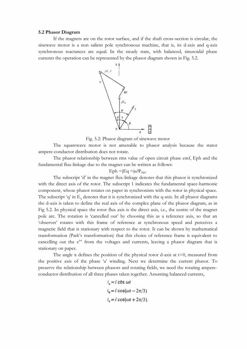
5.2 Phasor Diagram
If the magnets are on the rotor surface, and if the shaft cross-section is circular, the
sinewave motor is a non salient pole synchronous machine, that is, its d-axis and q-axis
synchronous reactances are equal. In the steady state, with balanced, sinusoidal phase
currents the operation can be represented by the phasor diagram shown in Fig. 5.2.
Fig. 5.2: Phasor diagram of sinewave motor
The squarewave motor is not amenable to phasor analysis because the stator
ampere-conductor distribution does not rotate.
The phasor relationship between rms value of open circuit phase emf, Eph and the
fundamental flux-linkage due to the magnet can be written as follows:
Eph =jEq =jωΨMd1
The subscript ‗d‘ in the magnet flux-linkage denotes that this phasor is synchronized
with the direct axis of the rotor. The subscript 1 indicates the fundamental space-harmonic
component, whose phasor rotates on paper in synchronism with the rotor in physical space.
The subscript ‗q‘ in Eq denotes that it is synchronized with the q-axis. In all phasor diagrams
the d-axis is taken to define the real axis of the complex plane of the phasor diagram, as in
Fig 5.2. In physical space the rotor flux axis is the direct axis, i.e., the centre of the magnet
pole arc. The rotation is ‗cancelled out‘ by choosing this as a reference axis, so that an
‗observer‘ rotates with this frame of reference at synchronous speed and perceives a
magnetic field that is stationary with respect to the rotor. It can be shown by mathematical
transformation (Park‘s transformation) that this choice of reference frame is equivalent to
cancelling out the ejωt from the voltages and currents, leaving a phasor diagram that is
stationary on paper.
The angle α defines the position of the physical rotor d-axis at t=0, measured from
the positive axis of the phase ‗a‘ winding. Next we determine the current phasor. To
preserve the relationship between phasors and rotating fields, we need the rotating ampere-
conductor distribution of all three phases taken together. Assuming balanced currents,

The axes of the three windings are displaced by 120 electrical degrees in such a way
that the rotor d-axis rotates past them in the sequence a, b, c. This gives rise to an ampere-
conductor distribution
The r.m.s. current in phase ‗a‘ is I amperes, and its phase relative to that of the open-
circuit flux-linkage of phase ‗a‘ is evidently lagging by the angle α. Correspondingly, the
rotating ampere-conductor lags the rotor d-axis and the flux by the same angle (measured in
electrical degrees). For positive motoring torque, the angle α must be negative, and we
substituted the angle β = -α which for motoring is positive. This is shown in Fig. 5.2. In
motoring, the axis of the ampere conductor distribution leads the rotor d-axis by the angle β,
as though the ampere- conductors were dragging the rotor behind them.
The phasor RI represents the voltage drop across the phase resistance, and is clearly
parallel to I. Similarly, the voltage drop across the synchronous reactance is represented by
jXsI and leads the current phasor by 90°. The sum of the back-e.m.f. and voltage drop
phasors must be equal to the applied voltage at the terminals. Thus
Figure 5.3 shows the phasor diagram with the current and voltages resolved into d-
and q-axis components. In both cases the resistance is neglected.
Fig. 5.3: Phasor diagram with resistance neglected, and with current and voltages resolved into d- and
q axis components: (a) ‗magnetizing‘ d-axis current; (b) ‗demagnetizing‘ d-axis current.

In Fig. 5.3(a) the current leads the d-axis by an angle less than 900 and lags the q-axis
by the angle γ, where
The minus sign simply means that y is measured from the q-axis in the normal
positive (anticlockwise) direction. The convenience of this will appear later.
The d-axis and q-axis components of current are given by
If Id is positive, as in Fig. 5.3(a), the armature or stator current produces an mmf
distribution around the airgap that tends to increase the d-axis flux produced by the magnet.
In this condition the armature reaction is said to be ‗magnetizing‘. The flux produced by the
stator m.m.f. induces the voltages jXsId in the q-axis, and –XsIq in the d-axis of the phasor
diagram. The q-axis component adds to jEq. The magnet flux-density is increased, so that
the operating point moves up the demagnetization characteristic.
In Fig. 5.3(b), Id is negative and the stator m.m.f. is negative and ‗demagnetizing‘.
The power factor angle is given by
and this is clearly less than in Fig. 5.3(a). In other words, a high power factor is associated
with operation in the demagnetizing mode. This also means that a highly coercive magnet
permits high power factor and reduces the kVA requirement in the converter.
5.3. Torque-speed characteristics of PMSM
Fig. 5.4: Torque-speed characteristics

Fig. 5.5: Torque- speed curve
The torque-speed curve of the motor is shown in fig. 5.5. The torque is produced by
the interaction of magnet flux and stator ampere conductor distribution. The rotor flux
produced by permanent magnet is constant. So the torque depends on stator flux.. Upto the
base speed is the constant torque region. Constant torque can be obtained by V/f control.
Base speed is also known as the corner speed. It is the maximum speed at which full torque
can be developed. For speeds above corner speed, the torque – speed characteristics enter
into field weakening region where torque decreases until it reaches zero.
The overall torque-speed characteristics of the motor is derived from the equation
𝑇 = 3𝑝𝐼𝐸𝑝
𝜔𝑠𝑖𝑛𝛽
The peak torque can be maintained up to the base speed. Above this speed, by modifying β,
the motor will effectively enter a field weakening mode, allowing an increase in the speed at
the expense of the peak torque. By suitably controlling torque angle β, d-axis current is
oriented in the negative (demagnetizing) direction. Peak torque is obtained when β =900 i.e,
when Id = 0 and Iq becomes the rated current.
5.4. CONTROL SCHEMES OF PMSM
5.4.1. Vector Control
For a BLPM motor to have better steady state and dynamic performance, it is
essential that the armature mmf axis and the axis of PM are to be in quadrature for all
operating condition. From the theory of BLPM sine wave motor it is known that as the
speed is varied from a very low value upto the corner frequency, the desired operating point
of current is such that Id = 0 and I is along the q-axis. Such a condition can be achieved by
suitably controlling the voltage by PWM technique after adjusting the frequency to a desired
value.
When the frequency is more than the corner frequency it is not possible to make Id
= 0, due to the voltage constraints. In such a case a better operating point for current is
obtained with minimum Id value after satisfying the voltage constraints.
Controlling BLPM sine wave motor taking into consideration the above mentioned
aspects is known as ―Vector Control‖ of BLPM sine wave motor.

Fig. 5.6: Schematic diagram of vector control
The schematic diagram of vector control is as shown in figure 5.6. Knowing the
value of the desired torque and speed and also the parameters and the voltage to which the
motor is subjected to, it is possible to compute the values of id ref and iq ref for the desired
dynamic and steady state performance.
The reference values of id and iq are transformed into reference values of currents
namely ia ref, ib ref and ic ref. These currents are compared with the actual currents and the
error values actuate the triggering circuitry which is also influenced by the rotor position
sensor and speed. Thus the vector control of BLPM SNW motor is achieved.
5.4.2. Self Control
As the rotor speed changes the armature supply frequency is also changed
proportionally so that the armature field always moves (rotates) at the same speed as the
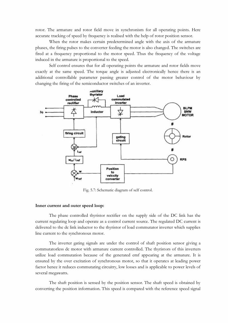
rotor. The armature and rotor field move in synchronism for all operating points. Here
accurate tracking of speed by frequency is realised with the help of rotor position sensor.
When the rotor makes certain predetermined angle with the axis of the armature
phases, the firing pulses to the converter feeding the motor is also changed. The switches are
fired at a frequency proportional to the motor speed. Thus the frequency of the voltage
induced in the armature is proportional to the speed.
Self control ensures that for all operating points the armature and rotor fields move
exactly at the same speed. The torque angle is adjusted electronically hence there is an
additional controllable parameter passing greater control of the motor behaviour by
changing the firing of the semiconductor switches of an inverter.
Fig. 5.7: Schematic diagram of self control.
Inner current and outer speed loop:
The phase controlled thyristor rectifier on the supply side of the DC link has the
current regulating loop and operate as a control current source. The regulated DC current is
delivered to the dc link inductor to the thyristor of load commutator inverter which supplies
line current to the synchronous motor.
The inverter gating signals are under the control of shaft position sensor giving a
commutatorless dc motor with armature current controlled. The thyristors of this inverters
utilize load commutation because of the generated emf appearing at the armature. It is
ensured by the over excitation of synchronous motor, so that it operates at leading power
factor hence it reduces commutating circuitry, low losses and is applicable to power levels of
several megawatts.
The shaft position is sensed by the position sensor. The shaft speed is obtained by
converting the position information. This speed is compared with the reference speed signal

which provides the speed error. This is the current reference signal for the linear current
loop. This reference current is compared with the sensed dc link current which provides
control signals for the rectifier thyristors. The sensed shaft position is used as gating signal
for inverter thyristor.
Load commutation is ensured only at high speeds. Whereas at low speeds the emf
generated is not sufficient for load commutation. The inverter can be commutated by
supplying pulsating on and off dc link current. This technique produces large pulsating
torque but this is not suitable for drives which require smooth torque at low speed.
The dc link current is pulsed by phase shifting the gate signal of the supply side
converter from rectification to inversion and back again. When the current is zero the motor
side converter is switched to a new conduction period and supply side converter is then
turned on. Time required for the motor current to fall to zero can be significantly shortened
by placing a shunt thyristor in parallel with a dc link inductor. When the current zero is
needed the line side converter is phased back to inversion and the auxiliary thyristor is gated.
The dc link inductor is then short circuited and its current can supply freely without
affecting the motor. When the line side converter is turned on the auxiliary thyristor is
quickly blocked. This method of interruption of the motor current reduces the effect of
pulsating torque.
Four Quadrant Operation:
The drive characteristics are similar to those of a conventional dc motor drive.
Motor speed can be increased to a certain base speed corresponding to the maximum
voltage from supply. Further, increase in speed is obtained by reducing the field current to
give a field weakening region of operation. Regenerative braking is accomplished by shifting
the gate signal, so that the machine side inverter acts as a rectifier and supply side rectifier as
a inverter, hence the power is return to the ac utility network. The direction of rotation of
motor is also reversible by altering the gate sequence of the motor side converter. Thus four
quadrant operation is achieved, without additional circuitry.


