CORK INSTITUTE OF TECHNOLOGY INSTITIÚID TEICNEOLAÍOCHTA CHORCAÍ Semester 2 Examinations 2009/10 Module Title: Introduction to Structural Design Module Code: CIVL6020 School: Building and Civil Programme Title: Bachelor of Engineering in Civil Engineering – Year 2 Programme Code: CCIVL_7_Y2 External Examiner(s): Ms. M. Kyne, Mr. J. Murphy Internal Examiner(s): Mr. T. McKenna, Ms. S. Corcoran Instructions: Answer ALL questions from each section Use separate answer books for each section Duration: 2 Hours Sitting: Summer 2010 Requirements for this examination: Candidates may refer to 1. ‘Approved Design Aids’ – (CIT Booklet) 3. ‘Designed & Detailed’ – (BCA Booklet) Note to Candidates: Please check the Programme Title and the Module Title to ensure that you have received the correct examination paper. If in doubt please contact an Invigilator.
Transcript
CORK INSTITUTE OF TECHNOLOGY INSTITIÚID TEICNEOLAÍOCHTA CHORCAÍ
Semester 2 Examinations 2009/10
Module Title: Introduction to Structural Design
Module Code: CIVL6020
School: Building and Civil Programme Title: Bachelor of Engineering in Civil Engineering – Year 2 Programme Code: CCIVL_7_Y2 External Examiner(s): Ms. M. Kyne, Mr. J. Murphy Internal Examiner(s): Mr. T. McKenna, Ms. S. Corcoran Instructions: Answer ALL questions from each section Use separate answer books for each section Duration: 2 Hours Sitting: Summer 2010 Requirements for this examination:
Candidates may refer to 1. ‘Approved Design Aids’ – (CIT Booklet) 3. ‘Designed & Detailed’ – (BCA Booklet)
Note to Candidates: Please check the Programme Title and the Module Title to ensure that you have received the correct examination paper. If in doubt please contact an Invigilator.
2
Section A –Reinforced Concrete
Q.A1 Reinforced Concrete Beam (Total 50 Marks)
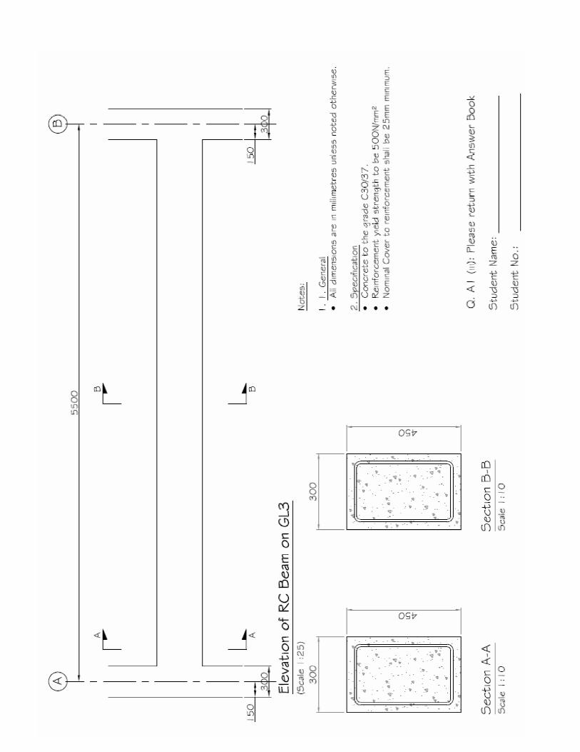
Figure Q.A1, details the slab, beam and column layout of a reinforced concrete structure. Design and prepare a detailed reinforcement drawing for the simply supported rectangular beam along gridline 3. Beam dimensions are as follows: b=300mm; h=450mm. (i) Determine the maximum design actions on the beam (10 marks) (ii) Design the simply supported beam along grid line 3 (35 marks) Note: No verification for Crack Control is required (iii) Prepare a reinforcement drawing for the beam designed in section A1. (i & ii) (5 marks)
Use the attached General Arrangement drawing to complete the detailed reinforcement drawing and include the completed drawing with your Answer Book.
Design Information for Q.A1:
Actions on the Structure: Permanent Actions:
Specific weight of reinforced concrete = 25 kN/m3 Weight of suspended ceiling & services = 0.6 kN/m2 Blockwork wall (2.5m height on all beams) = 2.5 kN/m2 of wall area
Variable Actions: Occupancy: Specific Use is ‘Office’ = 3.0 kN/m2
Weight of removable partitions/fittings = 1.0 kN/m2
Materials: Maximum Aggregate size: dg = 20mm Characteristic yield strength of steel reinforcement: fyk = 500 MPa Characteristic cylinder strength of Concrete: fck = 30 MPa Characteristic cube strength of Concrete: fck,cube = 37 MPa
(Cube Strength applies to Repeat Students designing to BS8110)
Cover: Nominal Cover: cnom = 25mm
Figure QA1
2 3
B
4000
300m
m x
450
mm
Bea
m
All beams to be 300mm wide x 450mm deep All Columns to be 300mm x 300mm All Slabs 200mm thick
1 4 3000 3000
A
200mm RC Slab
200mm RC Slab
200mm RC Slab
5500
3
Section A: Additional Information Additional Relevant Extracts from I.S. EN1992-1-1 9.2 Beams 9.2.1 Longitudinal reinforcement 9.2.1.1 Minimum and maximum reinforcement areas (1) The area of longitudinal tension reinforcement should not be taken as less than As,min Note 1: See also 7.3 for area of longitudinal tension reinforcement to control cracking. Note 2: The recommended value of As,min is given in the following:
As min = 0.26 fctm bt d ≥ 0.0013btd (Exp. 9.1N) fyk Where: bt denotes the mean width of the tension zone; fctm should be determined with respect to the relevant strength class according to Table 3.1. (3) The cross-sectional area of tension or compression reinforcement should not exceed As,max outside lap locations. Note: The recommended value of As,max for beams is 0,04Ac 9.2.1.2 Other detailing arrangements (1) In monolithic construction, even when simple supports have been assumed in design, the section at supports should be designed for a bending moment arising from partial fixity of at least β1 of the maximum bending moment in the span. Note 1: From Irish National Annex, β1 =0.25 Note 2: The minimum area of longitudinal reinforcement section defined in 9.2.1.1 (1)
applies. (3) Any compression longitudinal reinforcement (diameter φ) which is included in the resistance calculation should be held by transverse reinforcement with spacing not greater than 15φ. 9.2.2 Shear reinforcement (6) The maximum longitudinal spacing between shear assemblies should not exceed sl,max.
sl,max = 0,75d (1 + cot α ) (Exp 9.6N) where α is the inclination of the shear reinforcement to the longitudinal axis of the beam. (8) The transverse spacing of the legs in a series of shear links should not exceed st,max:
st,max = 0,75d ≤ 600 mm (Exp 9.8N)
4
Simplified Rules of Curtailment These following simplified rules of curtailment may be applied where:
a) For beams designed predominantly for Uniformly Distributed Loads (u.d.l’s) b) In the case of continuous beams, when the spans are approximately equal (not varying by
more than 15%)
Anchorage & Lap Lengths
Concrete Class C30/37
Reinforcement in Tension, bar diameter, Ø (mm) Bond Conditions 8 10 12 16 20 25 32 40